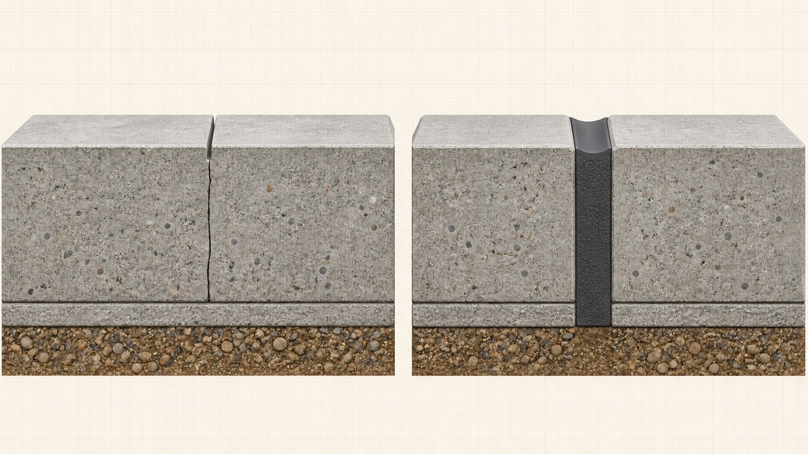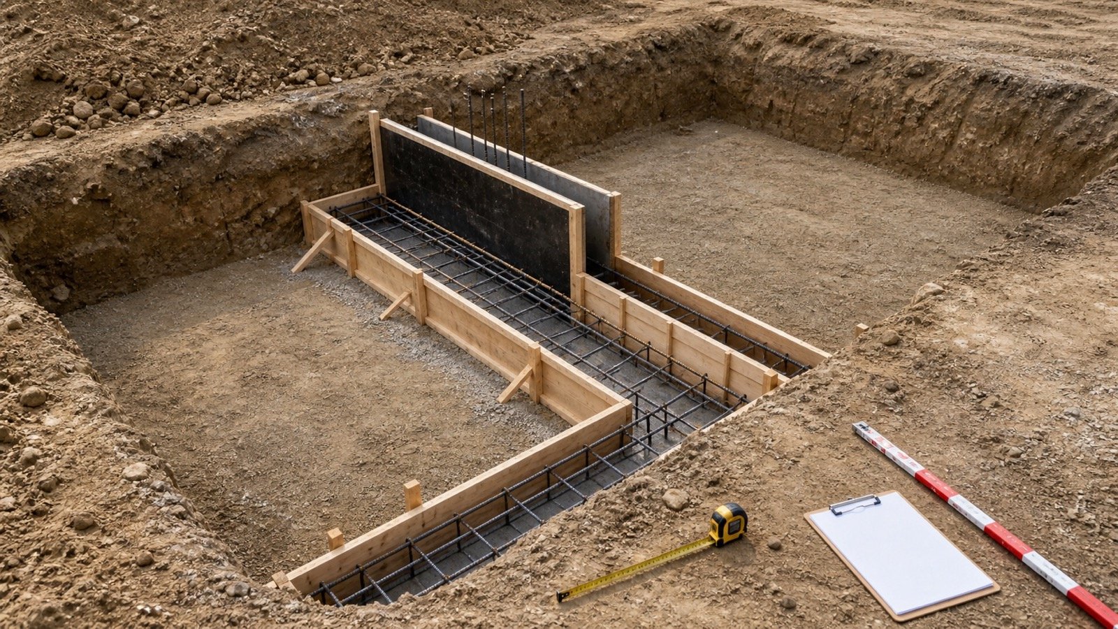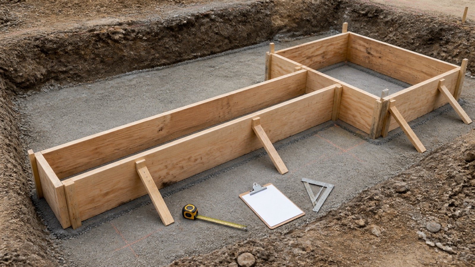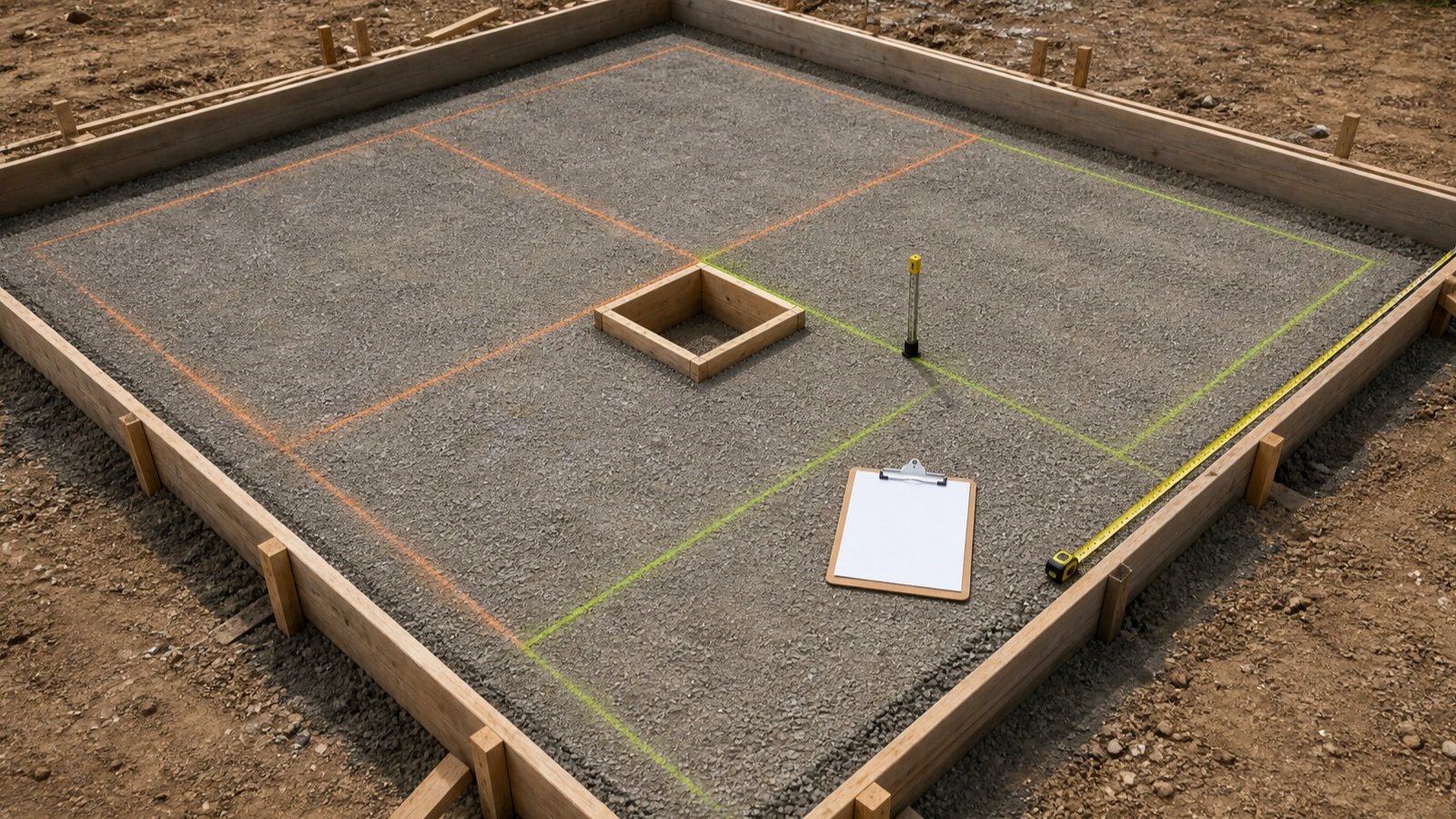
How do you find the correct concrete wall thickness?
Start with the current structural wall schedule and follow the wall mark to its plan, section, detail, notes, and revisions. Record the concrete-core thickness for each constant-thickness zone and resolve every conflict before calculating volume.
Use the Concrete Wall Calculator after the thickness source is accepted. The calculator converts centimetres or inches, but it cannot select or approve the dimension.
Write the wall mark, thickness, concrete boundary, drawing, revision, level, and limits on one row. A dimension without its source can drift when plans, sections, schedules, or field conditions change.
Which document should control the thickness input?
Use the document hierarchy stated in the project agreement and clarification process. The structural schedule often provides the fastest starting point, while sections and details define where each thickness begins and ends.
| Record | Thickness information | Required check |
|---|---|---|
| Structural wall schedule | Wall mark, type, thickness, concrete designation, and notes | Match the exact wall mark, level, and current revision |
| Structural plan | Location, extent, offsets, tags, steps, and thickness transitions | Trace each run to its section or detail reference |
| Section or enlarged detail | Concrete faces, top and base levels, keys, ledges, caps, and adjacent work | Keep concrete separate from finishes and forming systems |
| General notes and specifications | Design references, material requirements, tolerances, and exceptions | Apply the stated scope and precedence rules |
| Approved submittal or form layout | Selected ICF core or form spacing and zone transitions | Confirm consistency with the design documents |
| Revision, RFI, or field instruction | Approved change and affected locations | Replace the superseded row and preserve the difference |
Architectural plans help locate finishes, insulation, cladding, room dimensions, and openings. Use an architectural thickness as structural concrete only when the project documents and responsible design confirm that boundary.
What does concrete thickness exclude?
Concrete thickness covers the accepted concrete core. Keep removable forms, ICF foam faces, waterproofing, drainage board, insulation, finish coats, stone or brick veneer, air spaces, furring, liners, and protective boards outside that value.
| Layer | Concrete volume input? | Separate record |
|---|---|---|
| Cast-in-place concrete core | Yes | Wall mark and constant-thickness zone |
| Removable form face | No | Formwork system and contact area |
| ICF foam and webs | No | Exact product and assembly layout |
| Waterproofing or drainage layer | No | Face area, laps, terminations, and product coverage |
| Finish, cladding, or veneer | No | Its own material and support takeoff |
| Footing, pilaster, cap, key, or ledge | Separate geometry | Non-overlapping concrete zone |
A form's outside-to-outside width includes both form faces. An ICF block's overall width includes foam and web components. Enter the clear concrete cavity or approved core, subject to the selected system's actual geometry.
How should thickness changes be scheduled?
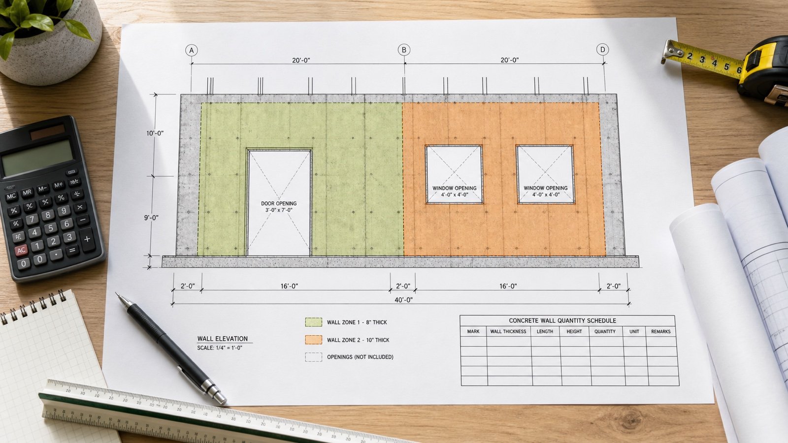
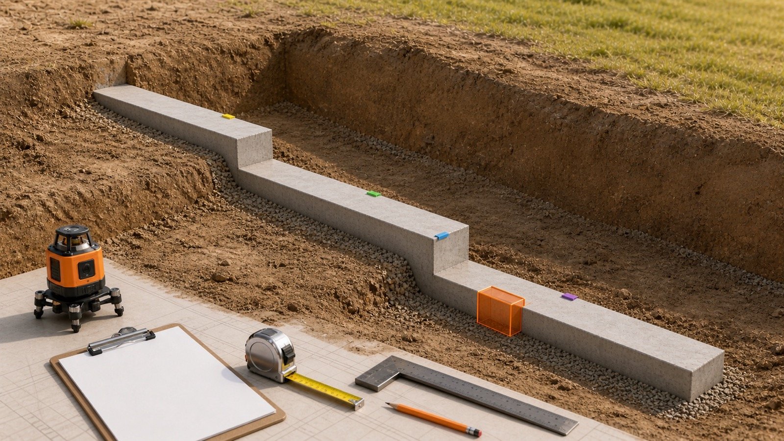
Split the wall at every approved thickness transition. Give each zone its own length, height, thickness, openings, concrete designation, and revision.
| Zone | Wall mark and limits | Concrete thickness | Reason for separate row |
|---|---|---|---|
| A | W1, grids 1 to 4, footing to Level 1 | 200 mm | Constant foundation-wall section |
| B | W1, grids 4 to 5, footing to Level 1 | 250 mm | Pilaster or local thickening shown separately |
| C | W1, grids 1 to 4, Level 1 to Level 2 | 150 mm | Approved upper-level transition |
| D | W2, curved run | Project value | Separate face and arc geometry |
Place the boundary at a named grid, joint, step, level, or dimension. Overlapping zones count concrete twice; a gap leaves concrete out of the schedule.
Why can't a common thickness table select the wall?
Wall function, height, lateral support, supported construction, soil, unbalanced backfill, groundwater, surcharge, wind, seismic conditions, openings, reinforcement, material properties, exposure, and adopted code can change the required design.
FEMA P-232 explains a limited residential foundation-wall context. Its September 2024 guide says its plain foundation-wall thickness range depends on wall height, soil classification, and unbalanced backfill. It also identifies an engineered-design boundary for certain walls exposed to groundwater pressure or more than 48 in of unbalanced fill without permanent support at both top and bottom.
Wisconsin SPS 321.18 provides another limited example. Its rule uses a jurisdiction-specific table unless structural analysis applies and links concrete foundation-wall thickness to the supported wall and unbalanced fill. A table from one jurisdiction or building category does not approve another project.
How should ICF concrete-core thickness be recorded?
Record the exact concrete core, product family, form unit, level, corner condition, and approved design reference. Keep the foam-to-foam assembly width in a separate field.
Nudura's current manufacturer guide says ICF core selection can change with building height, location, vertical and horizontal loads, above- or below-grade use, number of stories, soil, wind, and other project conditions. It warns against reducing the choice to a residential or commercial label.
- Confirm the straight-form core and any corner, taper-top, brick-ledge, pilaster, or transition units.
- Check whether different levels or zones use different cores.
- Verify the concrete cavity at intersections and special units.
- Keep webs, ties, foam, bucks, liners, and finishes outside the simple rectangular concrete-core width.
- Use the current approved layout for product quantities and the structural record for design acceptance.
How can thickness be checked before concrete placement?
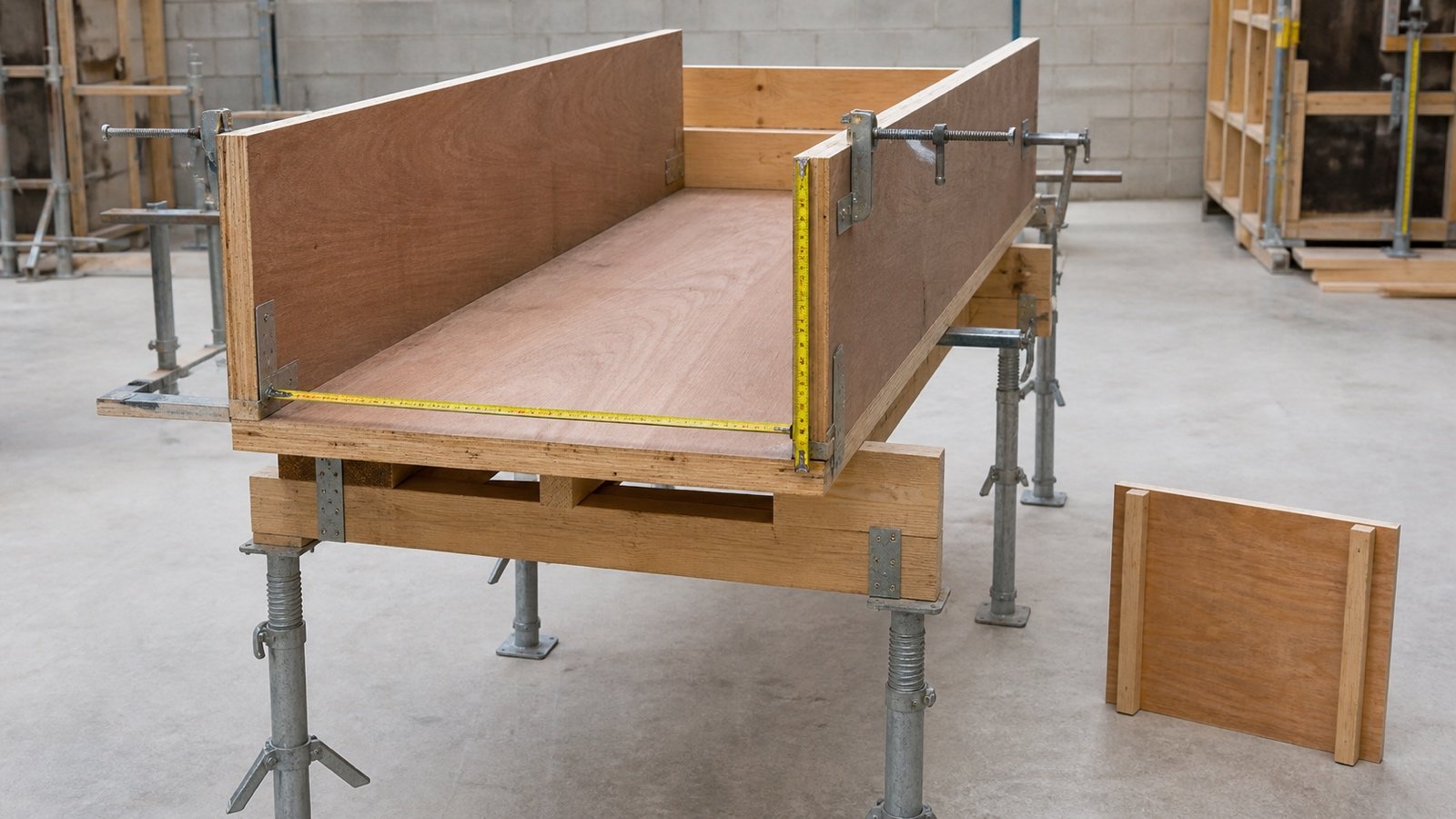
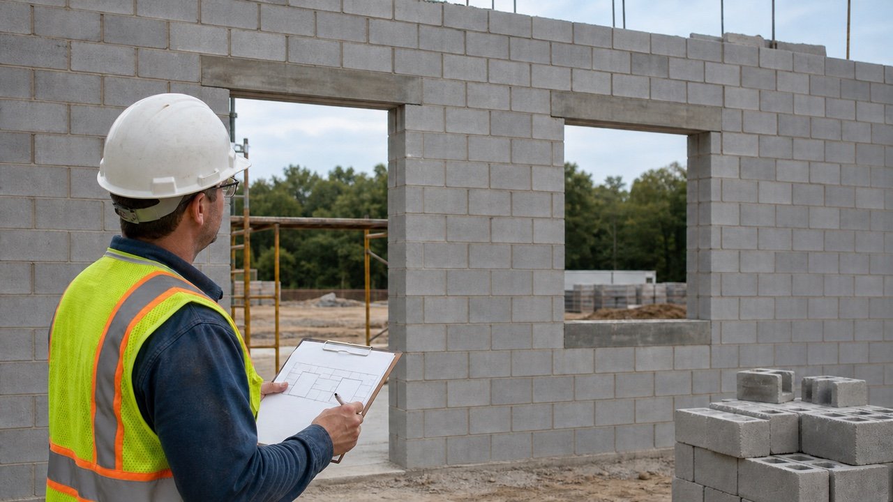
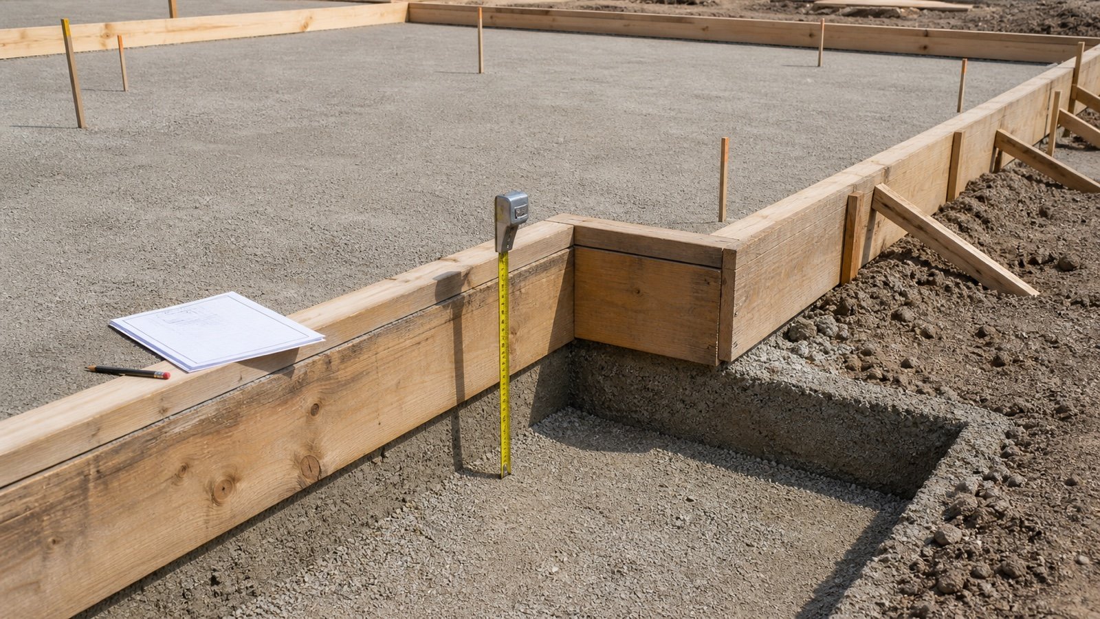
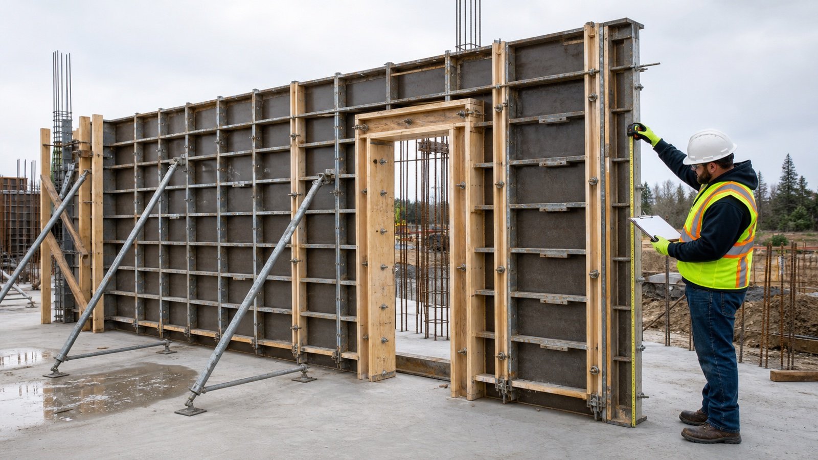
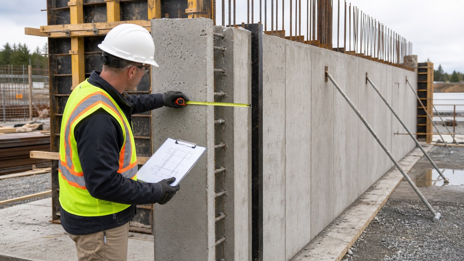
Check the clear concrete cavity at accessible form ends, openings, stop ends, and designated inspection points. Compare each reading with the wall mark, section, form layout, tolerances, and inspection plan.
- Confirm the form and drawing revisions.
- Identify the exact wall zone and intended concrete faces.
- Measure square to the faces at an approved accessible location.
- Check the base, top, bulkheads, openings, transitions, and offsets.
- Record location, reading, tool, date, checker, and disposition.
- Escalate a conflict through the project process before placement.
Form spacing at one end confirms one location. It does not prove the complete wall is parallel, plumb, aligned, stable, or ready for concrete. The formwork design, inspection process, and responsible site team control acceptance.
How can an existing wall be checked?
Start with as-built records, approved changes, survey data, and accessible concrete edges. A door, window, wall end, sleeve, or documented core location may expose the concrete boundary.
Remove finish thickness from the measurement only when you can identify each layer and measure it reliably. A surface-to-surface room measurement can include finishes, irregularity, or an inaccessible exterior face.
When the edge is hidden or the result affects structural work, a qualified party may specify calibrated nondestructive testing, exploratory openings, or coring. Record method, locations, equipment, uncertainty, repair, and professional interpretation. One local result cannot establish every wall zone.
How much does a thickness change affect concrete volume?
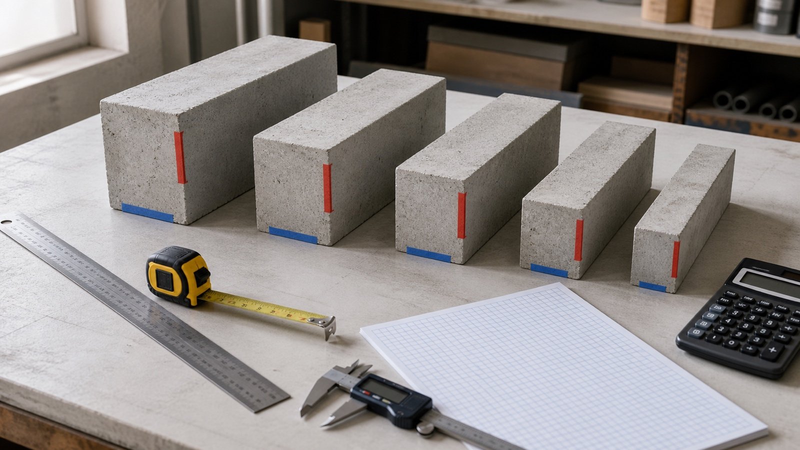
For the same wall length and height, concrete volume changes in direct proportion to thickness. Calculate the difference as plan area multiplied by the thickness change.
Volume difference = wall length × concrete height × (revised thickness − original thickness)
Metric example
A 12 m long by 3 m high wall changes from 150 mm to 200 mm. Convert both thicknesses to metres.
- 150 mm volume: 12 × 3 × 0.15 = 5.40 m³.
- 200 mm volume: 12 × 3 × 0.20 = 7.20 m³.
- Difference: 7.20 − 5.40 = 1.80 m³.
- Relative increase from the 150 mm basis: 1.80 ÷ 5.40 × 100 = 33.3333%.
The 50 mm thickness increase adds 1.80 m³ before openings, local thickenings, deductions, or an approved planning allowance.
Imperial example
A 40 ft long by 8 ft high wall changes from 8 in to 10 in.
- Thickness change: 2 in ÷ 12 = 0.1666667 ft.
- Volume difference: 40 × 8 × 0.1666667 = 53.3333 ft³.
- Cubic-yard difference: 53.3333 ÷ 27 = 1.9753 yd³.
Update form spacing, openings, returns, embeds, reinforcement coordination, supply, and placement records along with the concrete volume.
Should varying thicknesses be averaged?
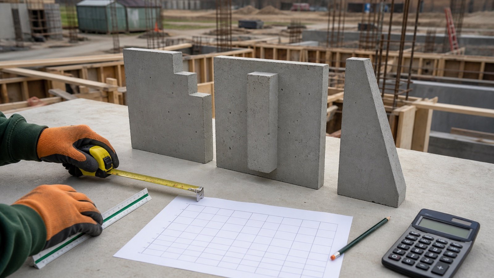
Use separate zones when the boundary and thickness of each zone are known. An average thickness can hide a step, taper, pilaster, battered face, void, or revision.
A weighted average can reproduce the total volume only after every zone volume is known:
Weighted average thickness = total wall volume ÷ total compatible wall plan area
This value can support a high-level reconciliation. Keep the original zone schedule because the average cannot place forms, identify transitions, coordinate openings, or price different work conditions.
What should the thickness record contain?
| Field | Record |
|---|---|
| Identity | Wall mark, level, grids, zone, and pour |
| Source | Drawing, schedule, detail, note, specification, RFI, and revision |
| Boundary | Concrete face-to-face, core, curve, batter, step, or taper |
| Dimensions | Length, height, thickness, units, and transition limits |
| Adjacent layers | Forms, foam, finishes, waterproofing, insulation, and cladding |
| Field check | Location, method, reading, tool, checker, and date |
| Quantity | Gross volume, opening deductions, local additions, and net volume |
| Status | Accepted, open, superseded, or revised with disposition |
HKIS includes wall mark, type, thickness, length, top and base levels, concrete designation, volume, and formwork-side area in its model quantity-information example. These fields provide a useful reconciliation set even when the project uses another modelling or measurement framework.
Common concrete wall thickness mistakes
- Using a typical detail without matching its wall mark and limits.
- Reading architectural assembly width as concrete thickness.
- Entering outside-to-outside form width.
- Using full ICF block width instead of the accepted concrete core.
- Applying one thickness to every level, grid, or pour zone.
- Missing pilasters, ledges, keys, steps, tapers, and local thickenings.
- Mixing millimetres with centimetres or inches with feet.
- Scaling a drawing when a written dimension or schedule conflicts.
- Averaging known zones and losing their boundaries.
- Using a common-thickness table as project design approval.
- Treating one field reading as proof of the complete wall.
- Changing the quantity without recording the revision difference.
Final thickness and quantity check
- Freeze the structural, architectural, specification, submittal, and revision set.
- Match every wall mark to its plan, schedule, section, and details.
- Separate concrete core from forms, foam, finishes, and adjacent components.
- Split changing thicknesses into non-overlapping zones.
- Resolve code, design, and document conflicts through the project process.
- Check accepted accessible locations before placement or record the existing-wall verification method.
- Use the Concrete Wall Quantity Takeoff to reconcile wall zones and opening deductions.
- Use the Concrete Wall Formwork Area guide for formed faces, openings, returns, and stop ends.
- Recalculate quantity differences at full precision.
- Release the record with preparer, checker, status, and date.
Return to the Concrete planning hub for the full cluster. The calculation methodology explains units, assumptions, and rounding, and the corrections route accepts a source or arithmetic issue.
Sources and source scope
- FEMA P-232 supports the cited residential foundation-wall variables, unbalanced-backfill definition, supported-wall relation, and engineered-design boundary in its stated scope.
- Wisconsin SPS 321.18 via Cornell LII supports the jurisdiction-specific example. Verify the current official code and local adoption before use.
- Nudura's ICF core guide supports the stated manufacturer context and project-variable list.
- HKIS BIM Measurement Information Requirements supports the stated wall quantity-information fields.
- NIST Handbook 44 (2026), Appendix C supports the unit relationships.
Source scope: FEMA provides a limited residential-code guide. Cornell LII mirrors one jurisdiction's regulation. Nudura provides manufacturer ICF context. HKIS supports quantity-information fields, and NIST supports unit relationships. These sources do not select or approve the reader's wall thickness, reinforcement, form system, testing method, code path, supplier order, or construction procedure.
Review note: Saleem Sial owns the research and editorial record. Formula fixtures, source checks, build validation, and rendered QA form the internal publication gate. Waseem Sial, External Reviewer and Engineer, is listed for ongoing external review; no completed review date is claimed.