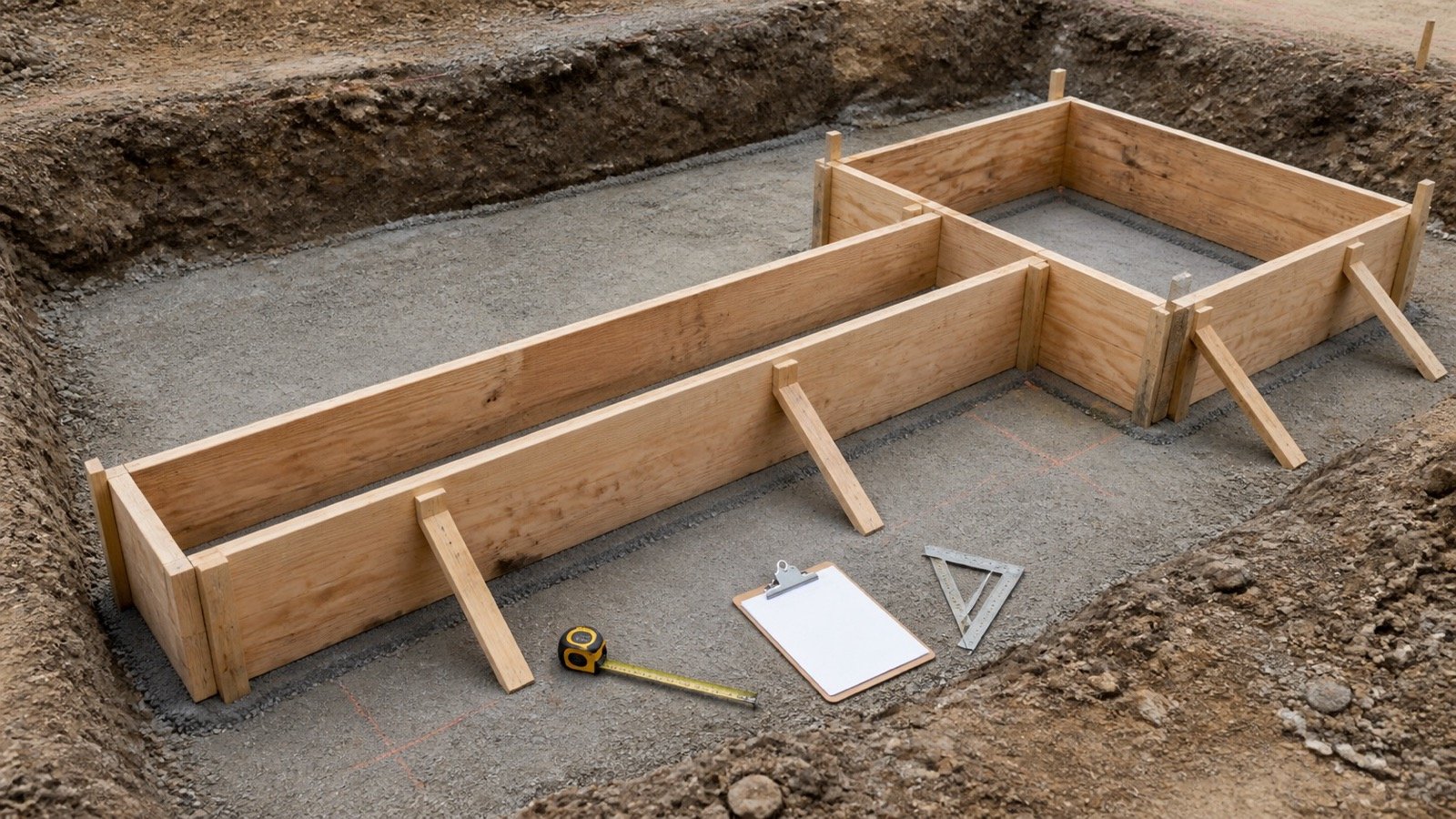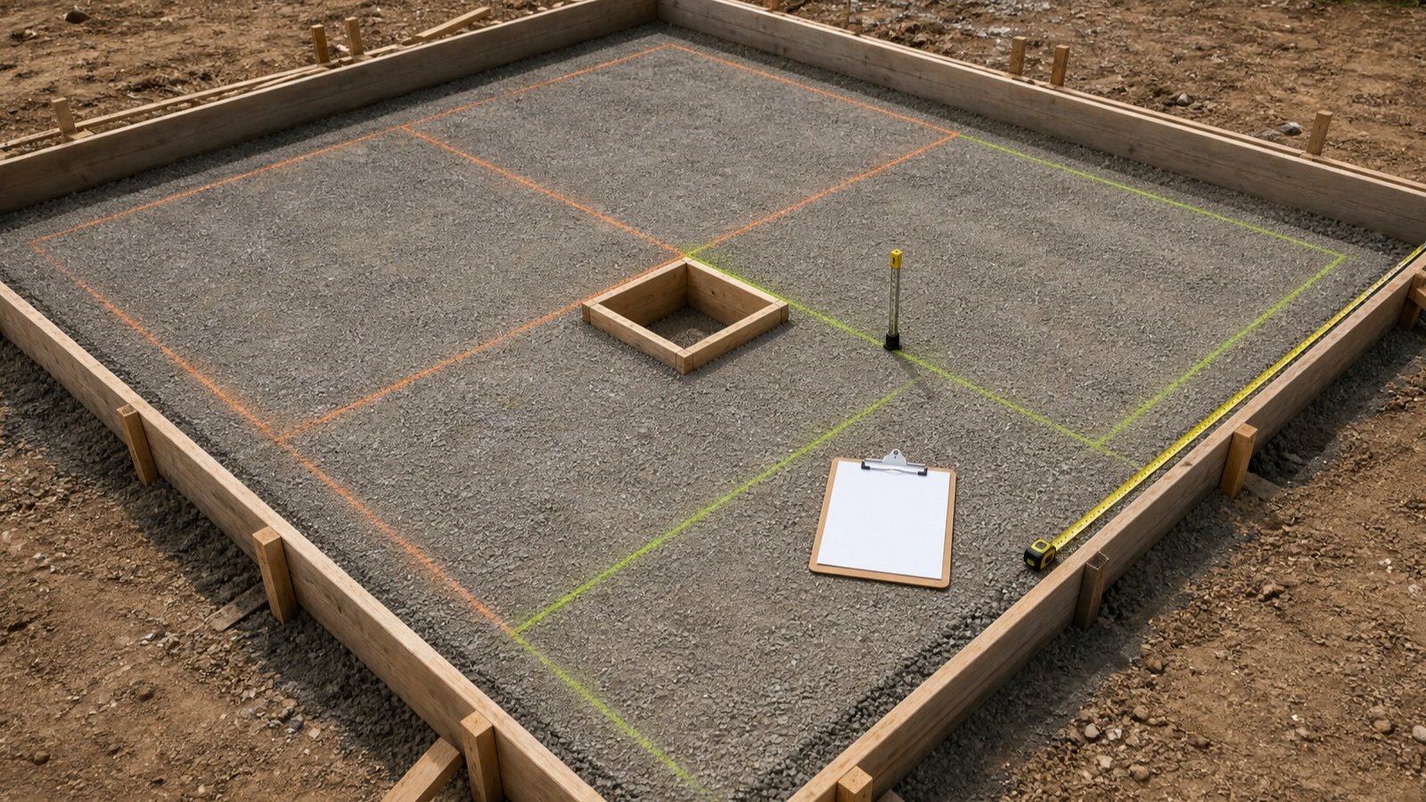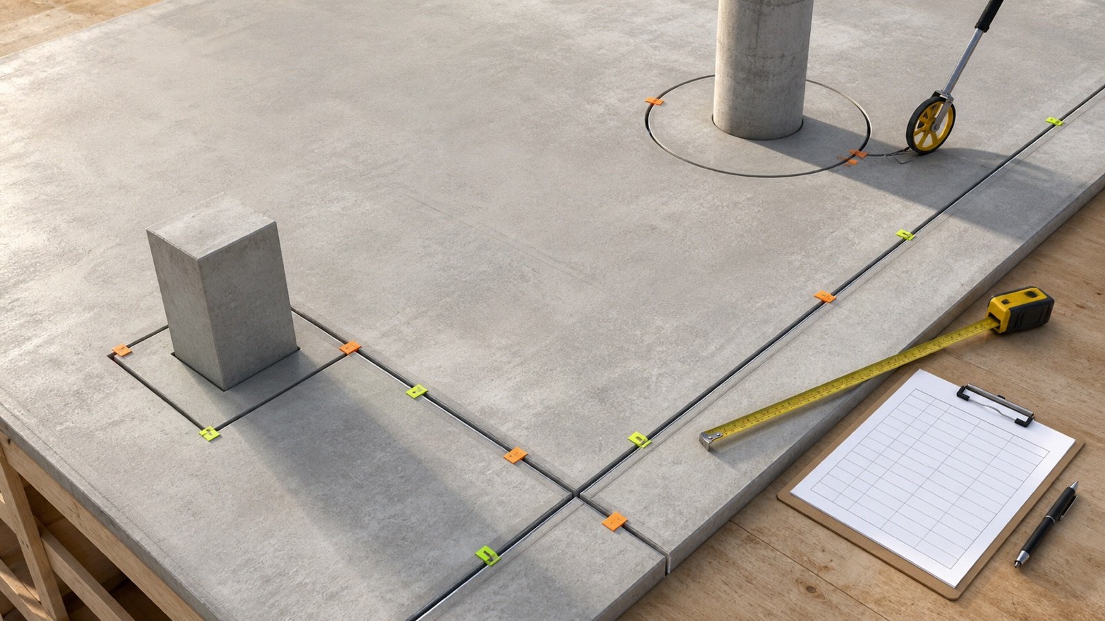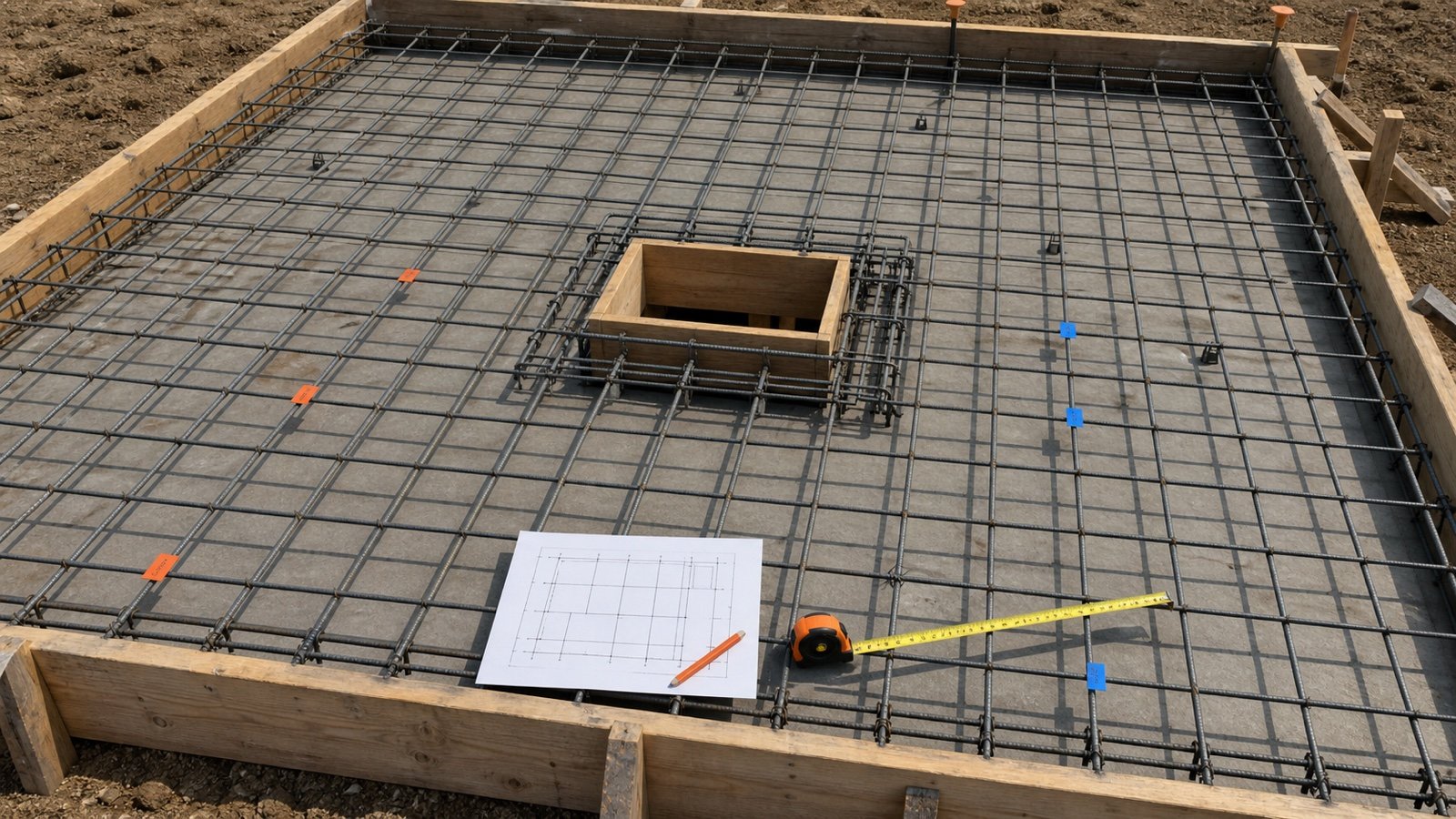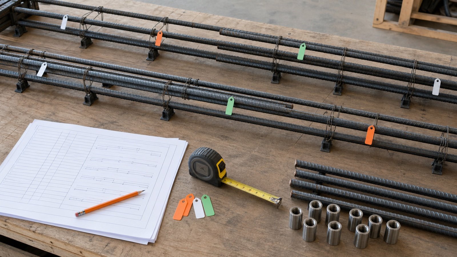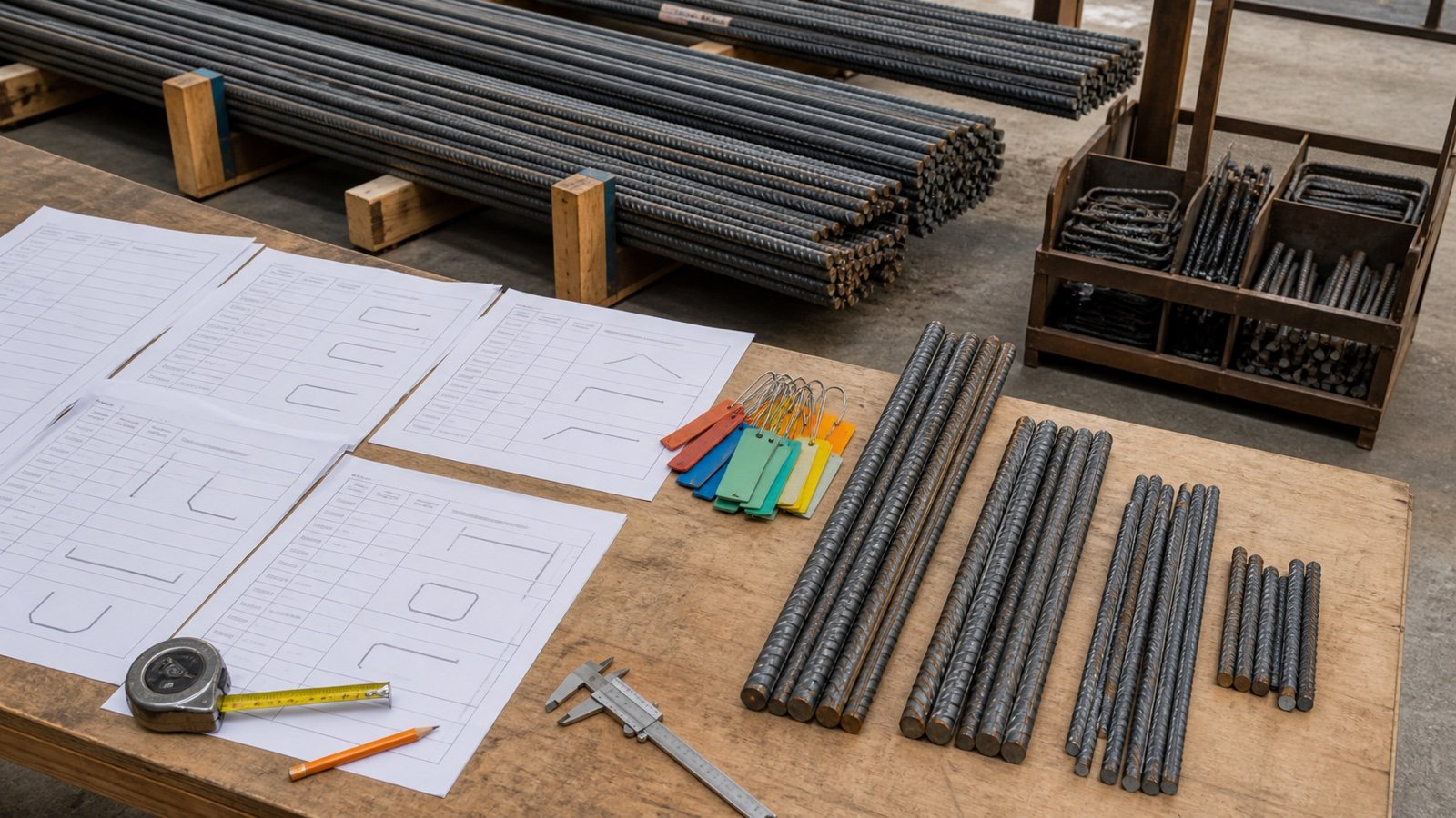
A rebar cutting list starts after the bar marks, quantities and fabrication dimensions have been checked against the current placing information. Each row should tell the shop or project team which piece to produce and where its source detail lives.
Stock planning comes later. Group compatible bars, test whole-piece cut patterns and record every reusable offcut that remains identifiable.
How do you make a rebar cutting list?
Create one row for each approved bar mark. Record the quantity, designation, grade, coating, straight or bent status, dimensions, total cut length, source drawing and release. Then group compatible straight pieces by available stock length and test cut patterns that produce every required piece.
CRSI defines a bar list as a bill of materials showing reinforcing-bar quantities, sizes, lengths and bending dimensions. ACI describes placing drawings as detailed information covering quantity, size, dimensions, spacing and location for fabrication and installation.
This workflow checks quantities and stock patterns. It does not generate hooks, bends, laps, development, couplers or shape-code dimensions. The responsible detailing and approval process supplies those values.
Which documents should be checked first?
Freeze one drawing and release set before preparing the list. A change to an opening, slab edge, splice zone or bar mark can change several rows at once.
| Record | Information used | Check |
|---|---|---|
| Structural drawings | Design sizes, locations, clearances, splices and termination requirements | Current issue and linked details |
| Placing drawings | Bar marks, quantities, dimensions, spacing, location and placing instructions | Approval level and revision |
| Bar list or schedule | Size, quantity, length, bend dimensions and total material | Matches the placing drawing |
| Project specification | Material, grade, coating, fabrication and submittal requirements | Project rule and applicable edition |
| Supplier stock record | Available lengths, product identity, bundle basis and delivery limits | Current written confirmation |
| Change record | Approved revision, request or field change | Affected marks and release status |
The slab rebar measurement guide shows how to split a slab into directions, layers and opening zones before those quantities reach the cutting list.
Which fields belong on each cutting-list row?
Use enough fields to identify the material, reproduce the quantity and trace the piece back to one approved detail.
| Field | Example | Purpose |
|---|---|---|
| Release and location | R2, slab S1 | Controls sequence and delivery destination |
| Bar mark | B12 | Connects list, drawing, tag and installed location |
| Quantity | 18 | States the required piece count |
| Designation | #5 / #16 | Separates stock by bar size |
| Grade and coating | As specified; uncoated | Separates incompatible stock and handling routes |
| Shape status | Straight or approved bend mark | Shows whether a simple length pattern applies |
| Approved cut length | 5.800 m | Controls each fabricated piece |
| Source | S-501 Rev 4, Detail 7 | Makes the row auditable |
| Calculated total | 104.400 m | Quantity multiplied by cut length |
| Pattern or fabrication reference | P-04 | Connects pieces to stock and shop instructions |
Keep accessories, couplers, supports and tie wire on their own records. A bar-mark list cannot prove that those items share the same material or purchasing unit.
How do straight and bent bars differ in the list?
A straight bar row can use one approved cut length. A bent bar row needs its approved shape mark, leg dimensions, bend information and resulting fabrication length from the governing detailing system.
Do not add leg dimensions or apply a memorized bend deduction unless the project-approved convention requires that method. ACI PRC-315-18 separates design details from fabrication details, and different standards or fabricators can express shapes and dimensions in different ways.
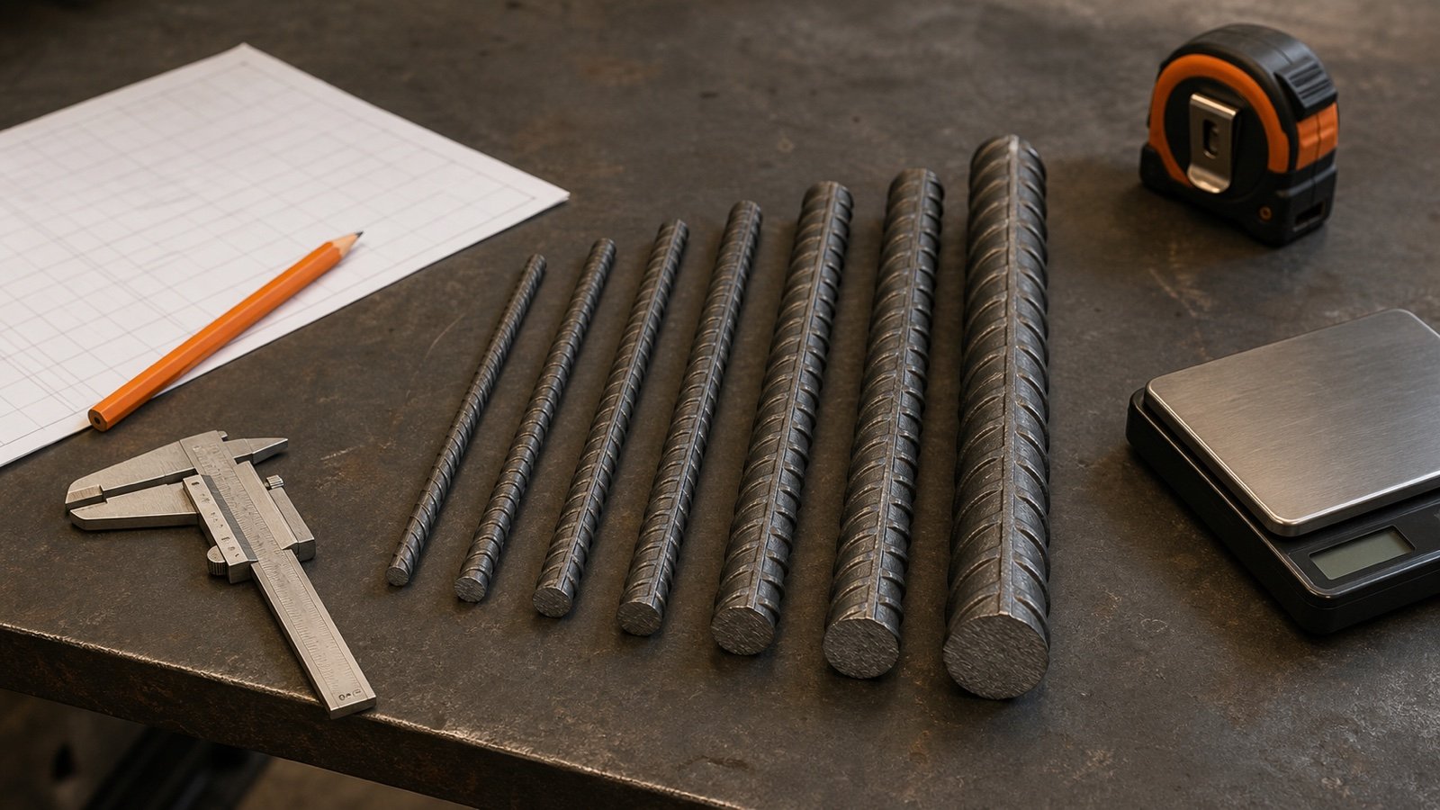
The Rebar Size and Weight Chart supplies nominal unit-weight references for #3 through #18. It does not calculate a bent shape or select a fabrication tolerance.
Which bars can share one stock pool?
Combine required pieces only when the stock product and fabrication route are compatible. Separate the pool whenever size, grade, coating, material specification, stock length, release or shop restriction changes.
| Attribute | Pool rule | Reason |
|---|---|---|
| Bar designation | Keep each size separate | A #5 piece cannot come from #4 stock |
| Grade and material | Use the accepted product record | Strength and certification differ |
| Coating or finish | Separate when product or handling differs | Damage, repair and identification controls differ |
| Stock length | List each available length | Patterns change with source length |
| Release and destination | Keep required delivery groups visible | A later pour cannot consume steel needed first |
| Offcut status | Use only identified and accepted pieces | Unknown material or length cannot support a traceable pattern |
The CADS Stock Bar Optimiser manual follows the same practical boundary by entering stock lengths for combinations of grade and diameter. Its offcut file also carries type, size, length, quantity, tag mark and weight.
How is the pooled stock lower bound calculated?
Add the required cut length for one compatible pool, divide by stock length and round upward.
Required cut length = sum(quantity x approved cut length)
Pooled stock lower bound = ceiling(required cut length / stock length)
The result is a length bound. Whole pieces must fit inside real stock bars, so the feasible order can be higher.
Worked example: why 190.2 m needs 17 stock bars
One approved #16 pool needs 18 straight pieces at 5.8 m and 22 pieces at 3.9 m. The supplier has confirmed 12 m stock for this example.
- Long pieces: 18 x 5.8 = 104.4 m.
- Short pieces: 22 x 3.9 = 85.8 m.
- Total required cut length: 104.4 + 85.8 = 190.2 m.
- Pooled lower bound: ceiling(190.2 / 12) = 16 stock bars.
Sixteen bars contain 192 m, yet the 5.8 m and 3.9 m pieces cannot be packed into those 16 bars as whole cuts. A feasible 17-bar plan uses 3 patterns:
| Pattern | Cuts from one stock bar | Stock bars | Pieces produced | Offcut per stock bar |
|---|---|---|---|---|
| A | 5.8 + 5.8 m | 7 | 14 long | 0.4 m |
| B | 5.8 + 3.9 m | 4 | 4 long and 4 short | 2.3 m |
| C | 3.9 + 3.9 + 3.9 m | 6 | 18 short | 0.3 m |
| Total | Approved whole pieces | 17 | 18 long and 22 short | 13.8 m total |
The pattern uses 204 m of stock and produces 190.2 m of required pieces. The difference is 13.8 m. Shop cutting loss, end condition and fabrication tolerance remain project and process inputs; this arithmetic does not hide them inside an invented percentage.
Worked example: a lower bound that is feasible
A separate #13 pool needs 12 straight pieces at 2.1 m from confirmed 12 m stock.
- Required cut length: 12 x 2.1 = 25.2 m.
- Lower bound: ceiling(25.2 / 12) = 3 stock bars.
- Five pieces fit within one 12 m stock bar because 5 x 2.1 = 10.5 m.
- Three stock bars can produce the required 12 pieces.
- Total offcut after the required cuts: 36 - 25.2 = 10.8 m.
The 3 unused pattern positions do not become fabricated bars. Record the remaining lengths after the approved cutting sequence and classify them under the project's offcut rule.
How should reusable offcuts be recorded?
Give each accepted offcut a unique tag and record its material identity, size, grade, coating, measured usable length, quantity, source release, location and status. Update the record when a piece is reserved, cut, damaged, rejected or returned.
A project or fabricator should define the minimum usable length and acceptance process. CADS treats that threshold as a user setting and separates qualifying offcuts from scrap. This page does not publish one universal cutoff.
| Field | Record |
|---|---|
| Offcut tag | Unique ID tied to storage location |
| Product identity | Designation, grade, coating and source record |
| Usable length | Measured length in the list's unit |
| Status | Available, reserved, consumed, rejected or scrap |
| New assignment | Release, bar mark and cut pattern using the piece |
| Check | Date and responsible person or process |
How do you reconcile the cutting list with delivery?
Match each delivered bundle and tag to the release, bar marks, quantities and product record before placement. FHWA's bridge-deck checklist calls for bundle-tag identification and checks of grade, size, type, coating, bending and length against the applicable requirements.
- Count bundles and pieces under each tag.
- Match bar marks and release numbers to the approved list.
- Check designation, grade, coating, length and bend identity.
- Record shortages, damage, substitutions and extra pieces.
- Keep accepted offcuts and returns under their current tags.
- Update the quantity record without erasing the issued baseline.
Which mistakes change the stock order?
- Dividing total length by stock length and calling the result an exact bar count.
- Pooling different bar sizes, grades or coatings.
- Using measured installed length where the row needs an approved fabrication length.
- Applying one lap or bend rule to unrelated marks.
- Counting an opening deduction without listing the added trimmer bars.
- Using an offcut whose tag or material identity is missing.
- Rounding each line before calculating the pool total.
- Optimizing across releases that need separate delivery dates.
- Changing a bar mark without revising its pattern and bundle tag.
- Calling every remainder reusable before the project accepts it.
What design, fabrication and safety limits apply?
The cutting list cannot select reinforcement, approve placing drawings, calculate code laps, define shape dimensions, authorize substitutions or certify fabrication. The project drawings, specifications, approved details, fabricator procedures and responsible professionals control those decisions.
Cutting, bending, bundling, lifting and storing rebar require suitable equipment, trained personnel and site controls. OSHA 29 CFR 1926.701(b) requires guarding protruding reinforcing steel where a fall could cause impalement in covered U.S. construction work. Follow the applicable rules for the work location.
Use the Rebar Calculator to establish the straight installed length and stock bounds for a qualifying rectangular grid. The Concrete Planning hub connects the remaining concrete and reinforcement quantity tasks.
Sources and source scope
- CRSI Reinforced Concrete Terminology: bar-list, fabrication, structural-drawing, lap and related reinforcing terms.
- ACI PRC-315-18 public page and preview: design details, fabrication details, placing drawings and review scope.
- CRSI Placing Reinforcing Bars, 10th Ed public page: current publication scope for bar lists, fabrication tolerances, handling, tagging and field safety.
- CADS Stock Bar Optimiser manual: stock-length pools, grade and diameter grouping, cut-pattern reports and offcut records.
- FHWA Bridge Deck Rebar Checklist: bundle identification and checks of specified grade, size, coating, bending, length, placement and splice location in its bridge-review context.
- NIST Guide to the SI, Appendix B: exact foot, inch and metric conversions.
- OSHA 29 CFR 1926.701: United States protruding-rebar impalement protection context.
Source scope: CRSI and ACI support terminology and detailing context. CADS documents one stock-optimization workflow. FHWA supports its named bridge checklist, NIST supports conversions, and OSHA supports the stated U.S. workplace rule. Project documents, accepted fabrication data, supplier records and responsible professionals govern the actual work.
Review note: Saleem Sial owns the research and editorial record. Source checks, independent cut-pattern fixtures, editorial review, build validation, link crawl, schema review and rendered QA form the internal publication gate. Waseem Sial, External Reviewer and Engineer, is listed for ongoing external review; no completed review date is claimed.