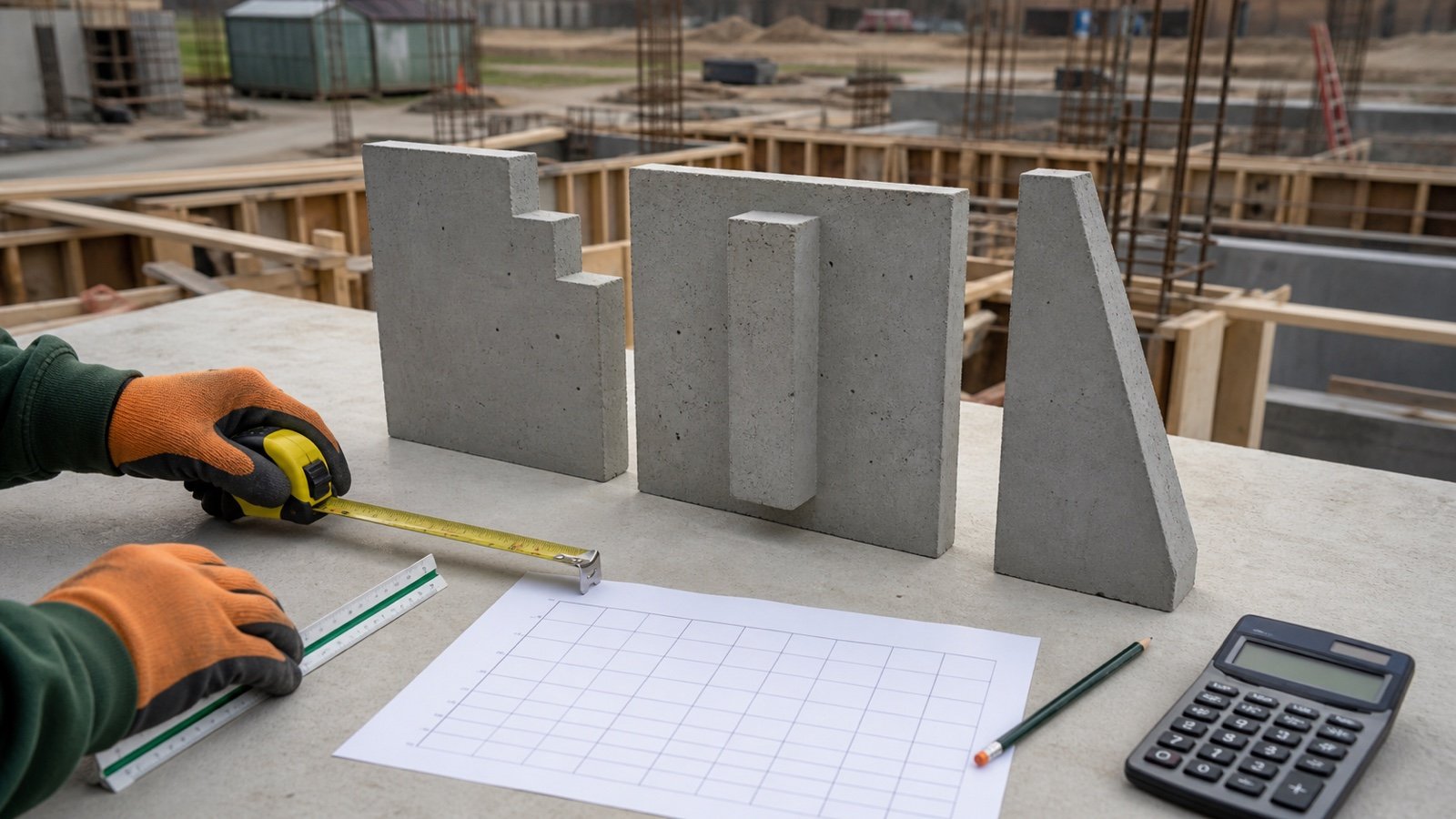
How do you calculate concrete volume for a special wall shape?
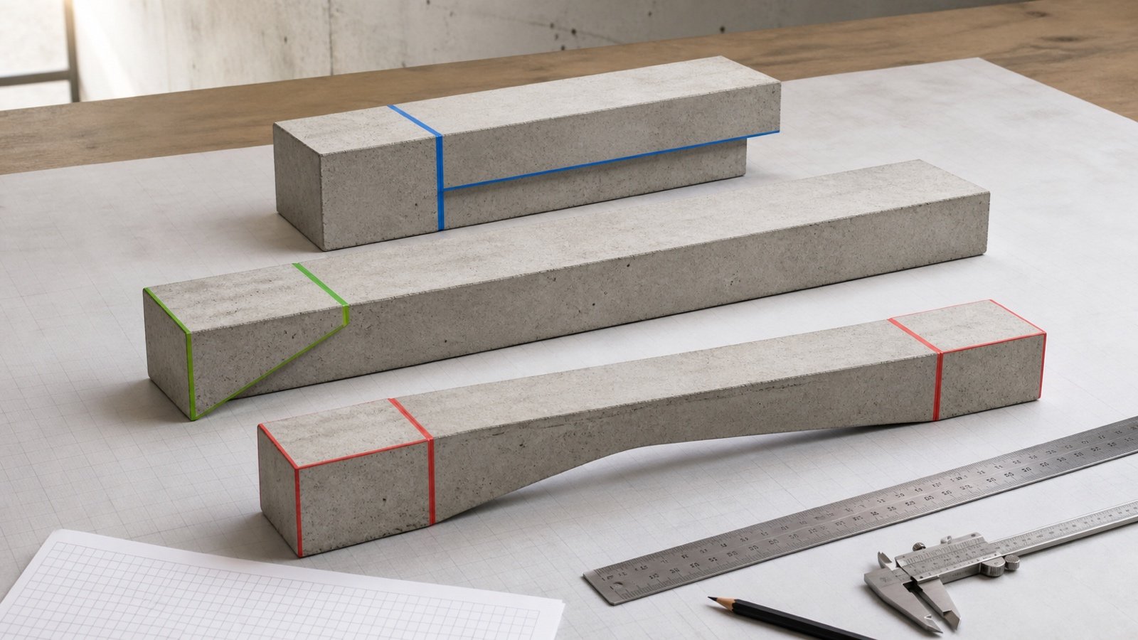
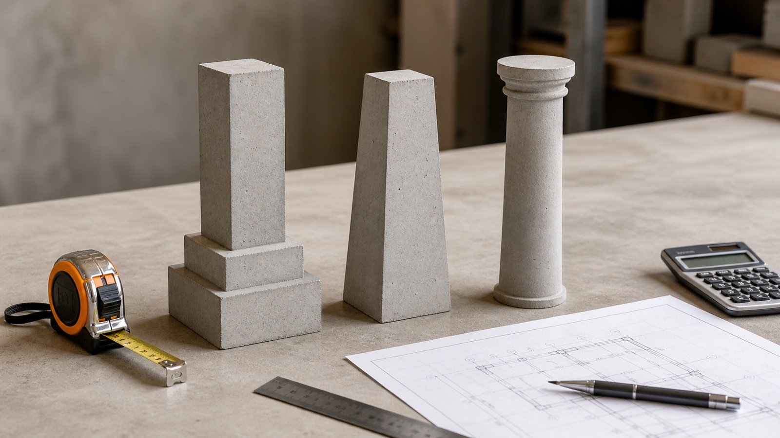
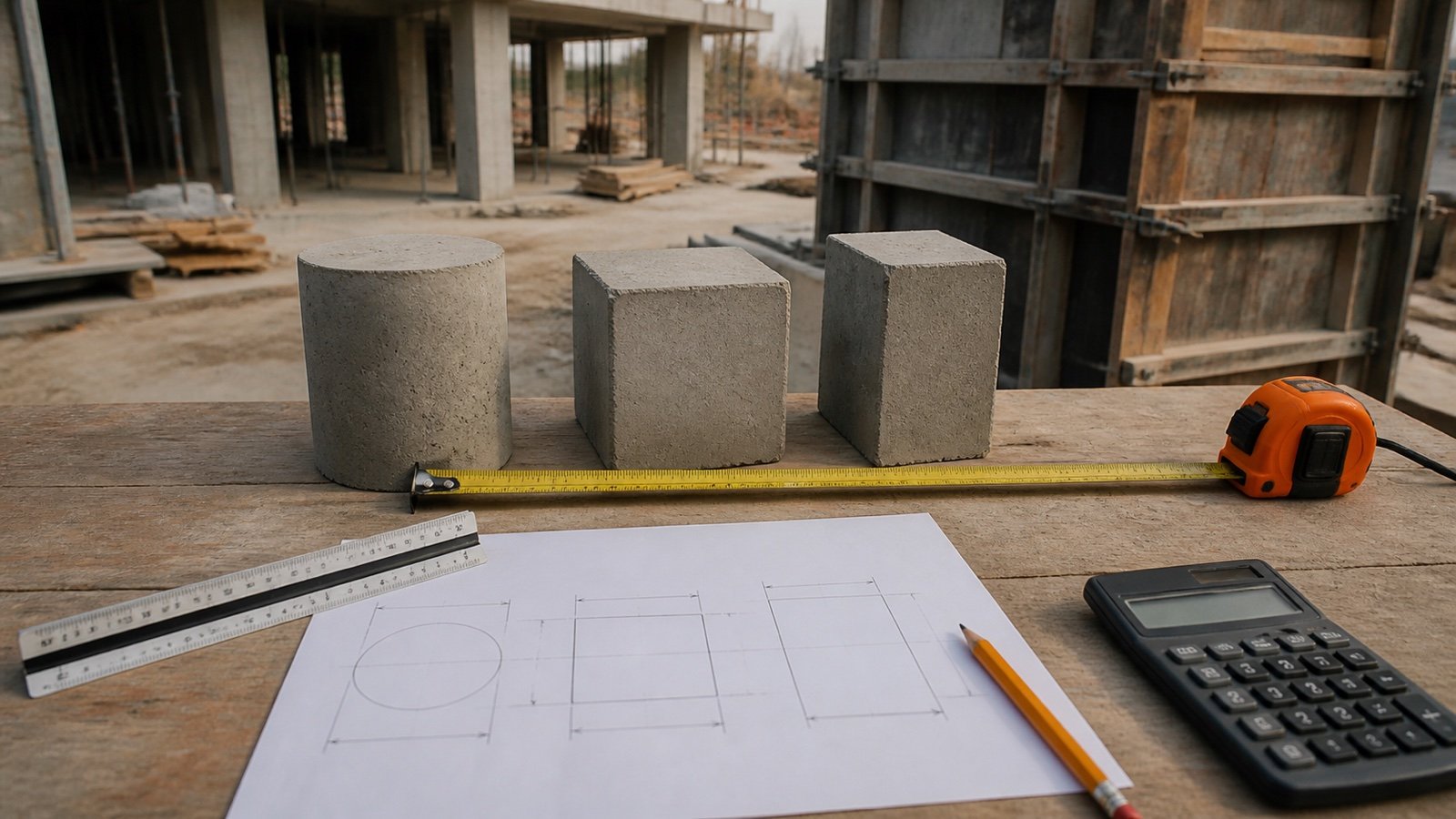
Split the wall into non-overlapping solids that match the current plan and section. Calculate each solid in compatible units, assign it as a base, addition, or deduction, then sum the unrounded volumes.
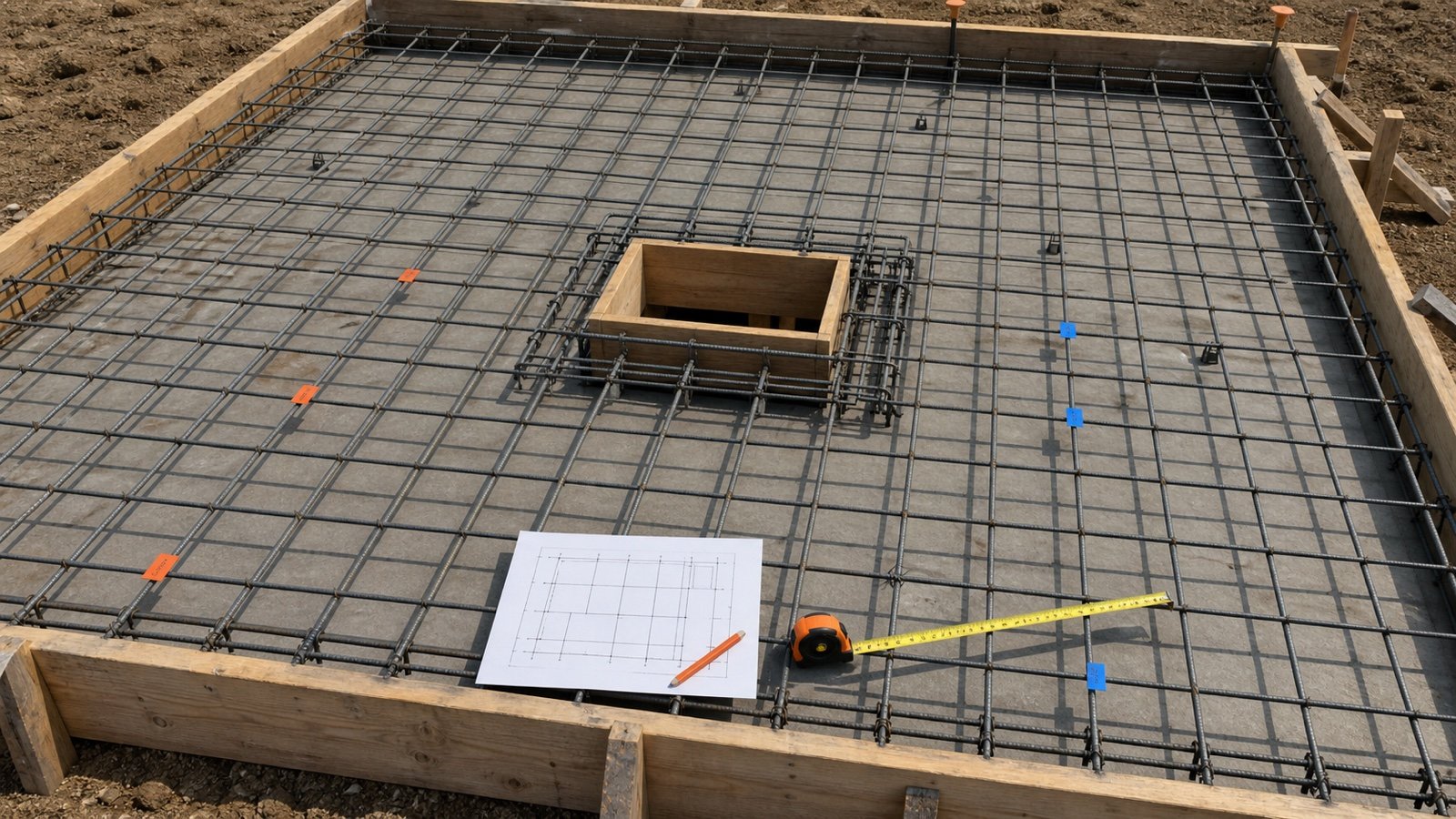
Use the Concrete Wall Calculator for every rectangular constant-thickness zone. Keep tapered, battered, or curved parts in the special-shape schedule until their geometry has been checked.
Net wall volume = sum of base zones + additions − deductions
A pilaster can overlap the parent wall, a step can overlap the lower zone, and a model can merge two objects. Record the shared solid under one row before adding the schedule.
Which records define the concrete boundary?
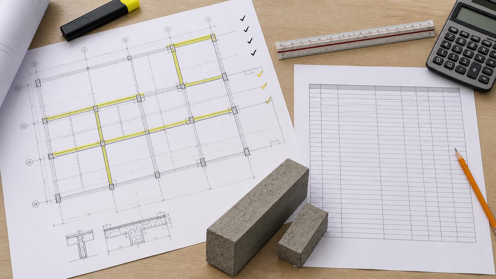
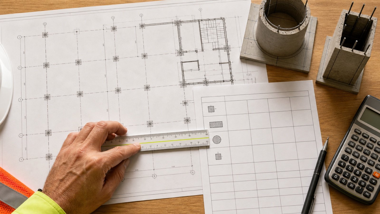
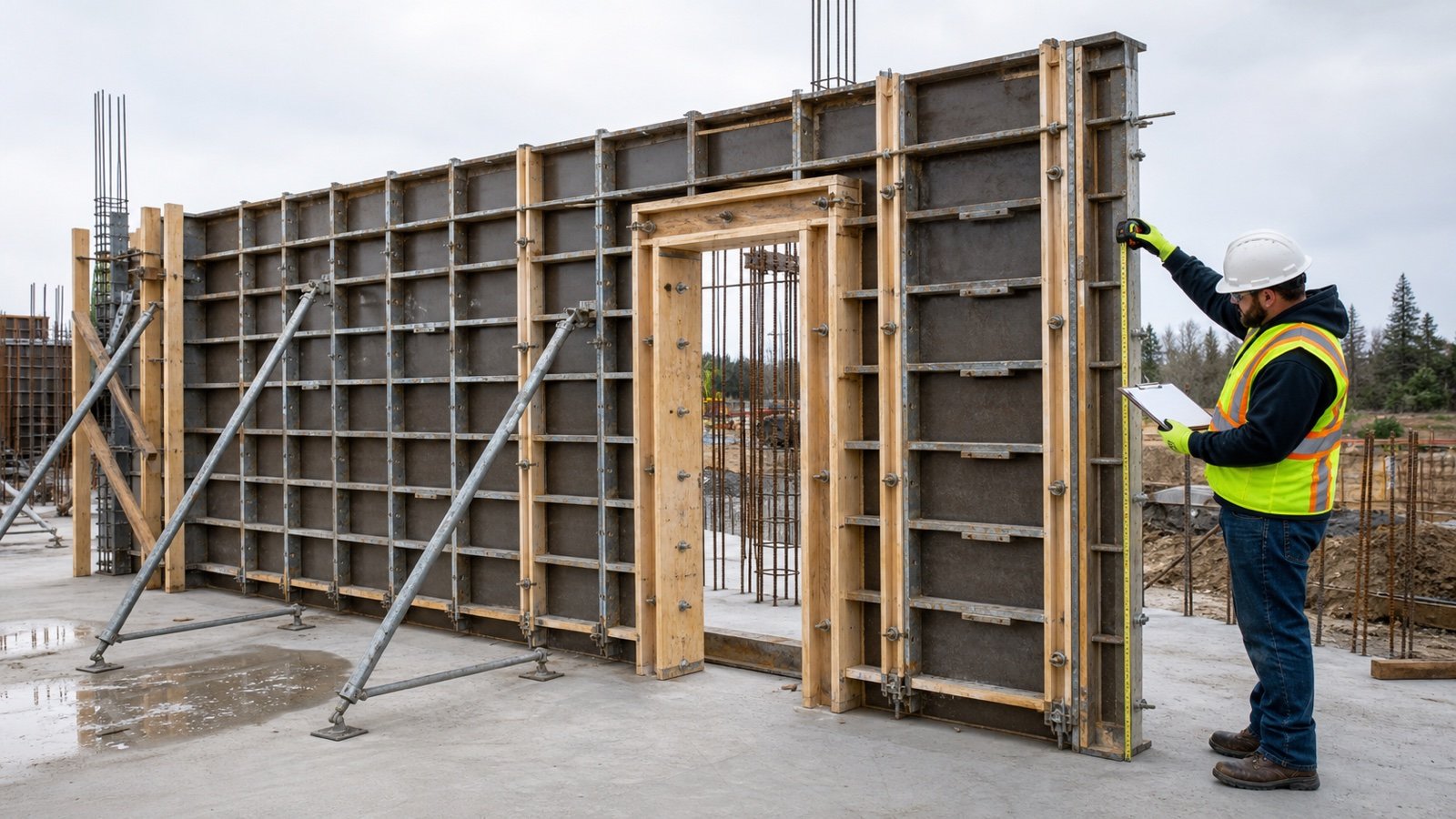
Start with the current structural wall mark, plan, section, details, levels, and revisions. Record the dimension direction as well as the number because a horizontal thickness, radial thickness, perpendicular thickness, sloping length, and vertical height describe different boundaries.
| Record | Information to capture | Release check |
|---|---|---|
| Wall plan | Wall mark, run limits, curve centre, radii, offsets, returns, and pilaster location | Match every special shape to a named grid, station, or dimension |
| Section or elevation | Top and base levels, step boundaries, taper direction, battered face, and projection | Confirm which dimensions are vertical, horizontal, radial, perpendicular, or along the slope |
| Detail | Pilaster width and projection, ledge, key, recess, haunch, or local thickening | Identify the shared volume with the parent wall |
| Wall schedule | Type, thickness, concrete designation, level, and notes | Use the exact mark and current revision |
| Model or quantity schedule | Object ID, special-shape flag, dimensions, volume, joins, and exclusions | Compare a sample with manual geometry and inspect object intersections |
| Approved field record | Accepted changed boundary, location, date, method, and disposition | Keep the design quantity and field change on separate traceable rows |
The HKIS BIM Measurement Information Requirements lists wall marks, wall types such as vertical, sloping, and curved, concrete strength, width, area, volume, and formwork fields. The ArchSD BIM Guide for Cost Estimation shows an RC wall schedule with special shape, length, width, height, volume, mark, and element code. These fields make a useful audit record even when the project uses another software or measurement standard.
How should a stepped concrete wall be divided?
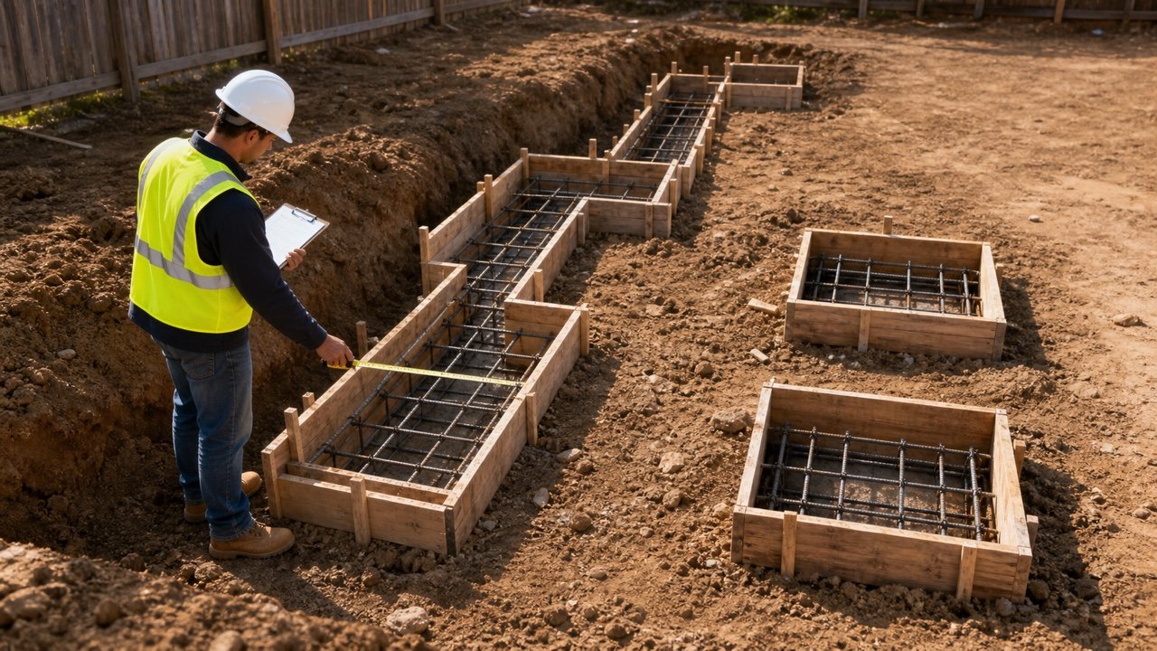
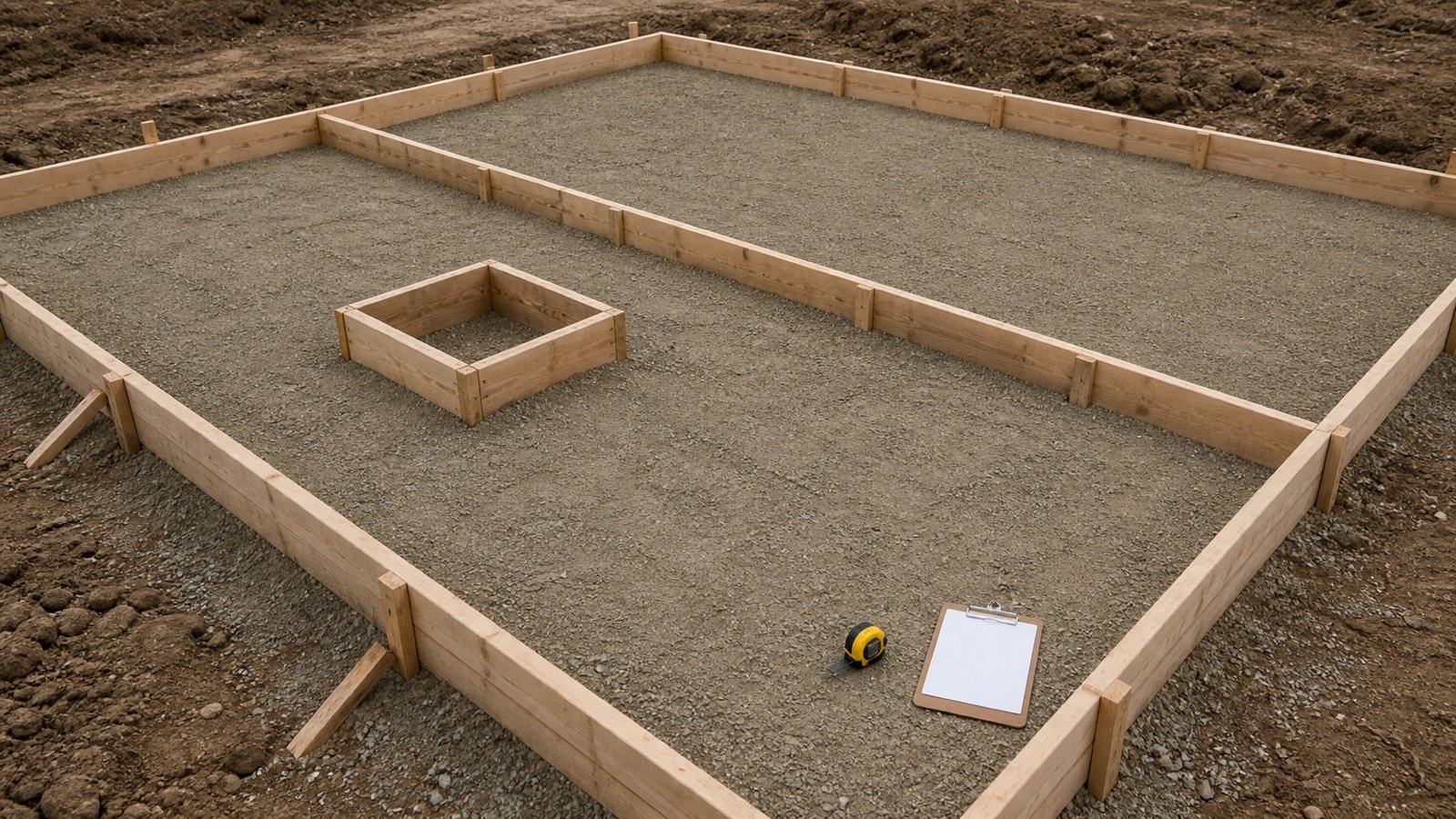
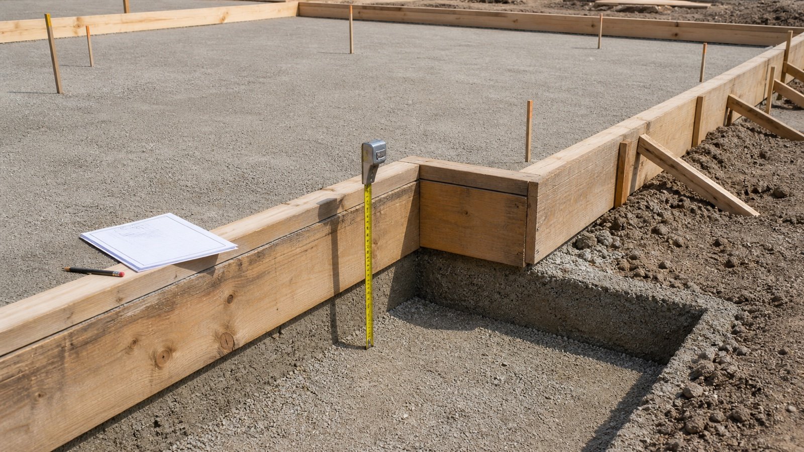
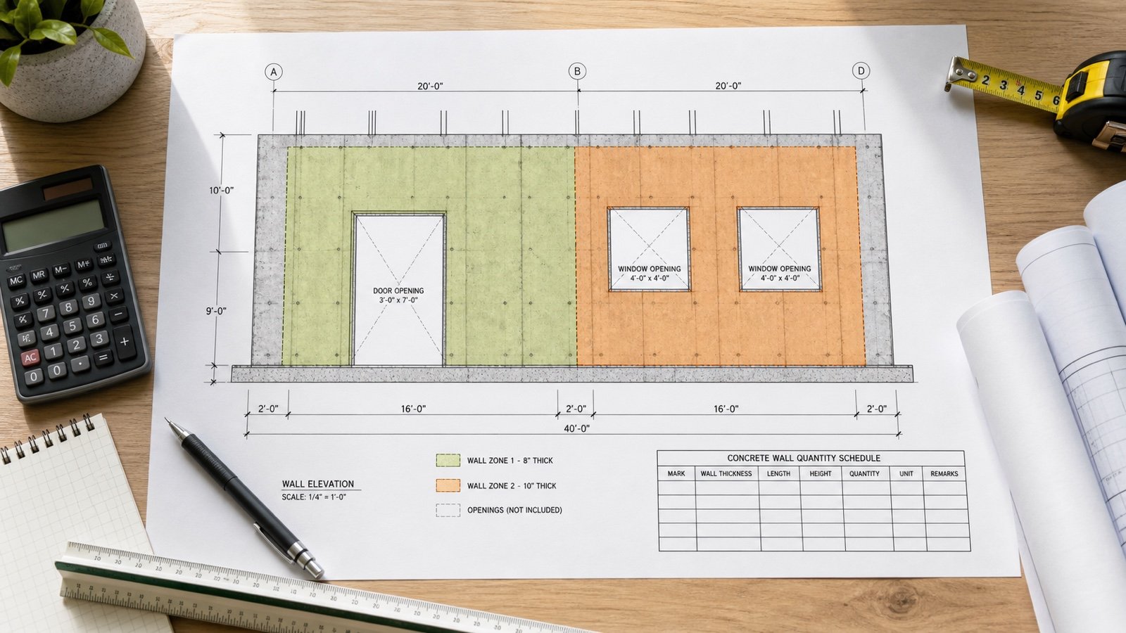
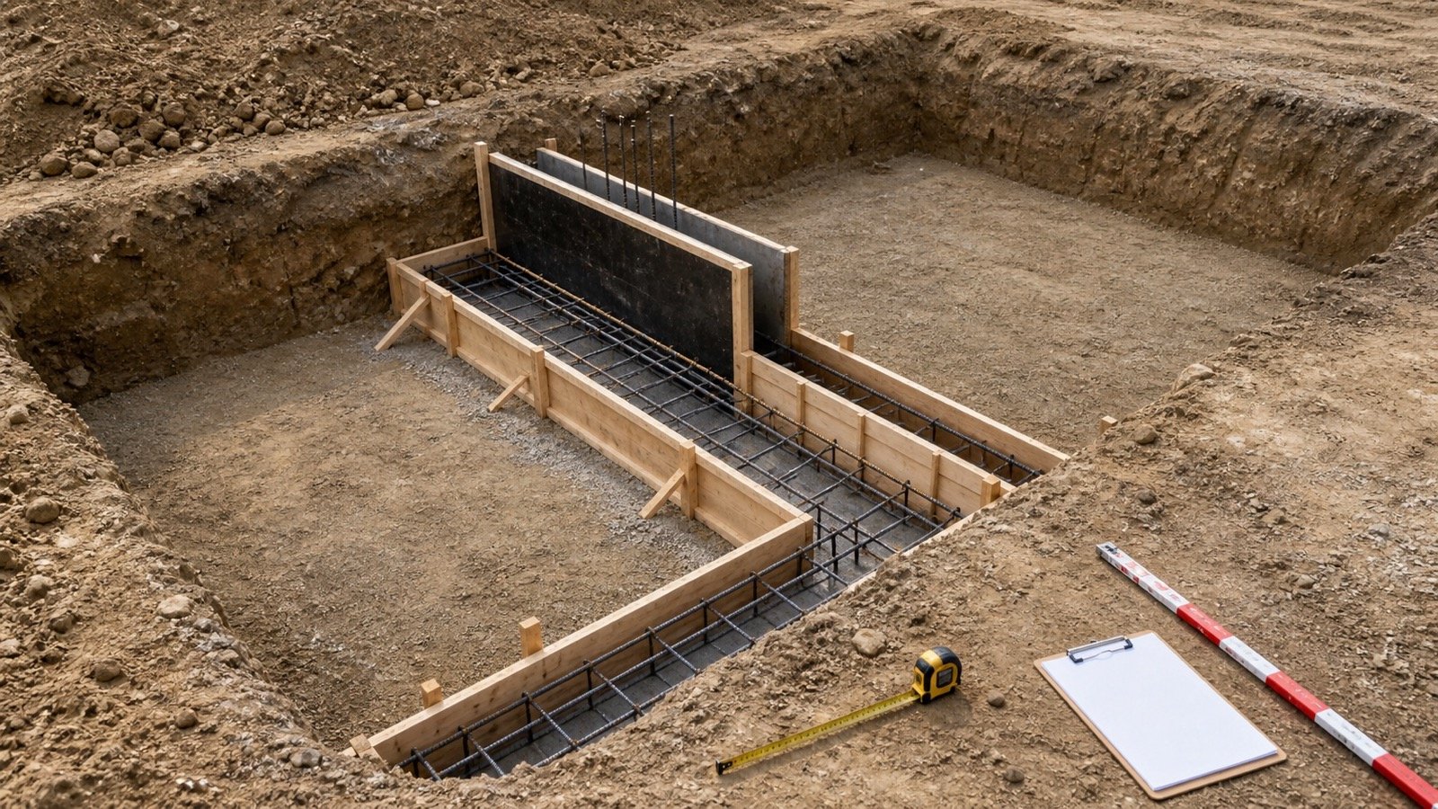
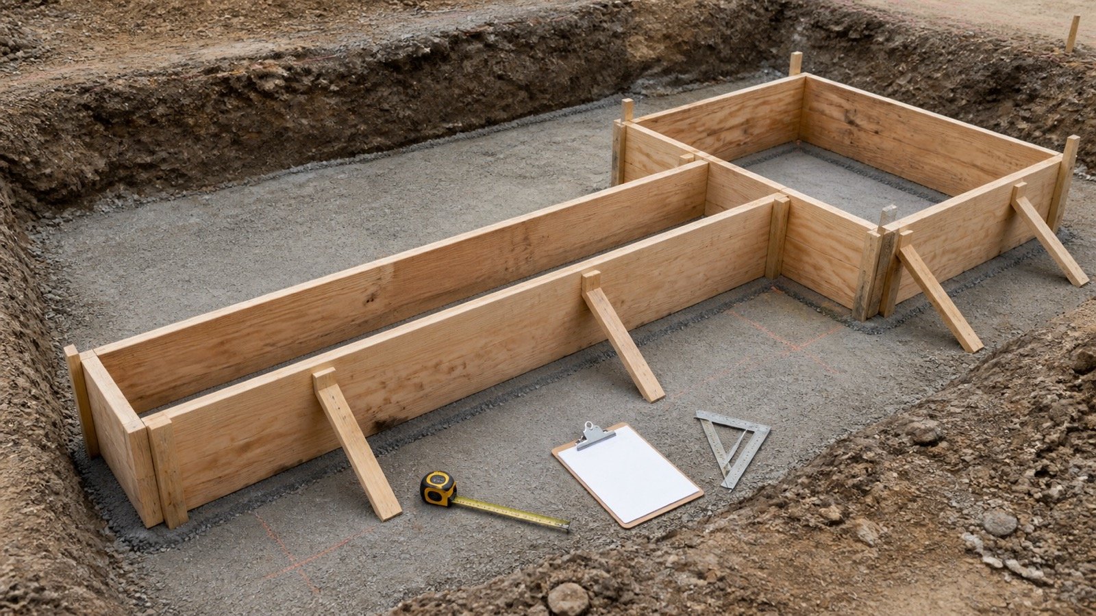
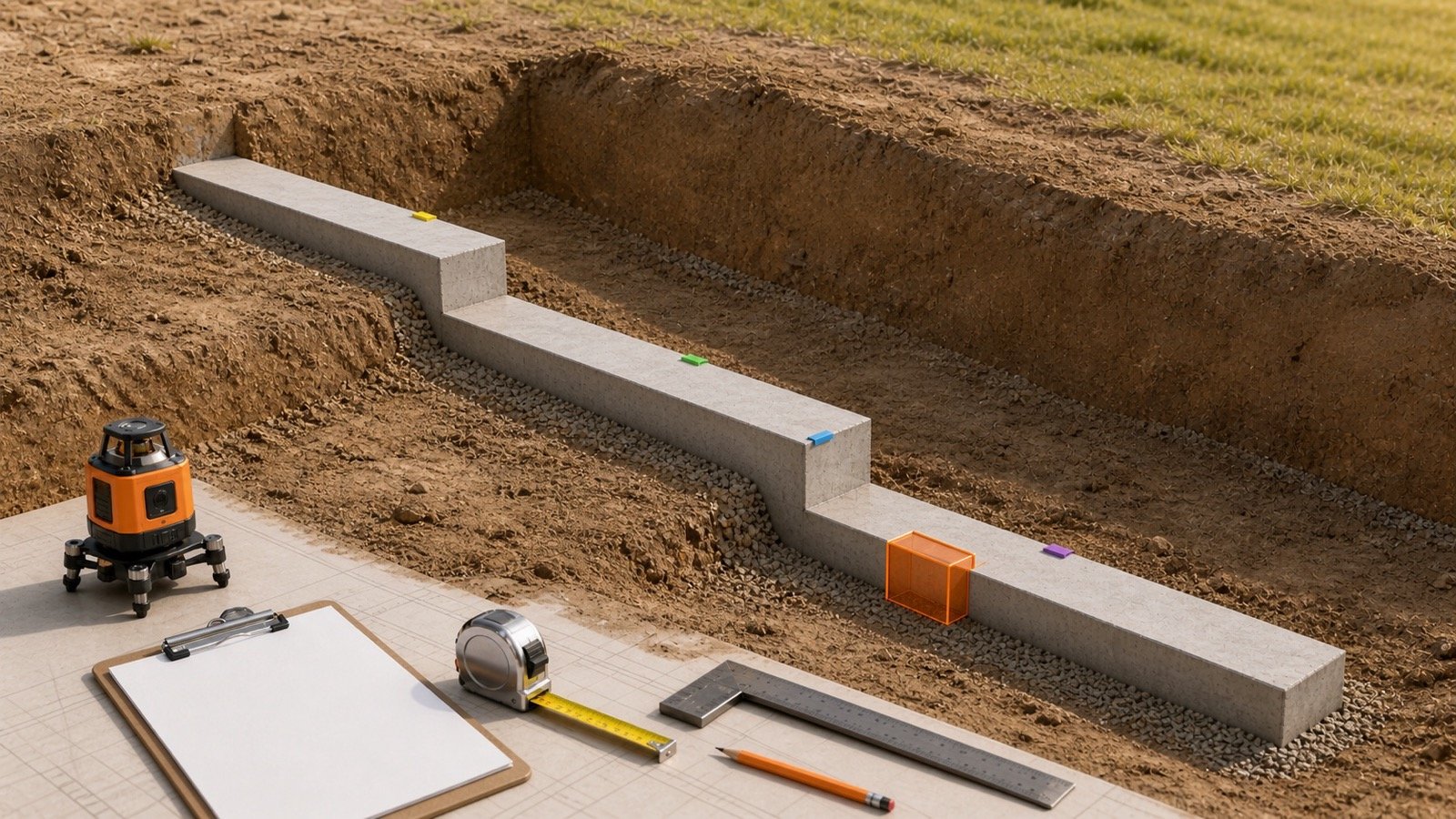
Split the wall at every top-level, base-level, or thickness change. Each row needs its own length, concrete height, thickness, and limits.
Stepped wall volume = Σ(length of zone × height of zone × thickness of zone)
Do not calculate the full wall at the highest level and add the upper steps again. That method counts the step zones twice.
Metric example: 2 wall levels and 1 pilaster
A 10 m wall has a 6 m long zone at 3 m high and a 4 m long zone at 2.40 m high. Both zones are 200 mm thick. A rectangular pilaster projects 250 mm beyond one face for 600 mm along the wall and 2.40 m high.
| Row | Calculation | Volume | Ownership |
|---|---|---|---|
| Base A | 6 × 3 × 0.20 | 3.60 m³ | High wall zone |
| Base B | 4 × 2.40 × 0.20 | 1.92 m³ | Lower wall zone |
| Addition P1 | 0.25 × 0.60 × 2.40 | 0.36 m³ | Pilaster projection outside the wall face |
| Total | 3.60 + 1.92 + 0.36 | 5.88 m³ | One count for each solid |
The fixture uses approved dimensions as arithmetic inputs. It does not select the wall height, thickness, step, or pilaster.
How do you add a pilaster without counting the wall twice?
Calculate only the pilaster concrete outside the wall volume that has already been measured. For a rectangular projection on one face, multiply the outside-face projection by the pilaster width along the wall and its concrete height.
Rectangular pilaster addition = outside-face projection × width along wall × height
If the drawing gives the pilaster's full depth, subtract the parent wall thickness in the same direction before calculating the addition. A pilaster that projects from both faces needs 2 separate projection rows when the sides differ.
| Dimension shown | Quantity action |
|---|---|
| Projection beyond one wall face | Use that projection directly for the addition |
| Full pilaster depth across the wall | Remove the already-counted wall depth before adding the outside part |
| Pilaster width along wall | Use the actual local width, subject to any taper or changing profile |
| Pilaster starts above or stops below the wall | Use its own top and base levels |
| Haunched or tapered pilaster | Use its checked cross-sectional area or separate solids |
Columns, counterforts, buttresses, wall returns, and intersecting walls may have another object owner or measurement rule. Record the parent element and intersection decision explicitly.
When can average thickness be used for a tapered wall?
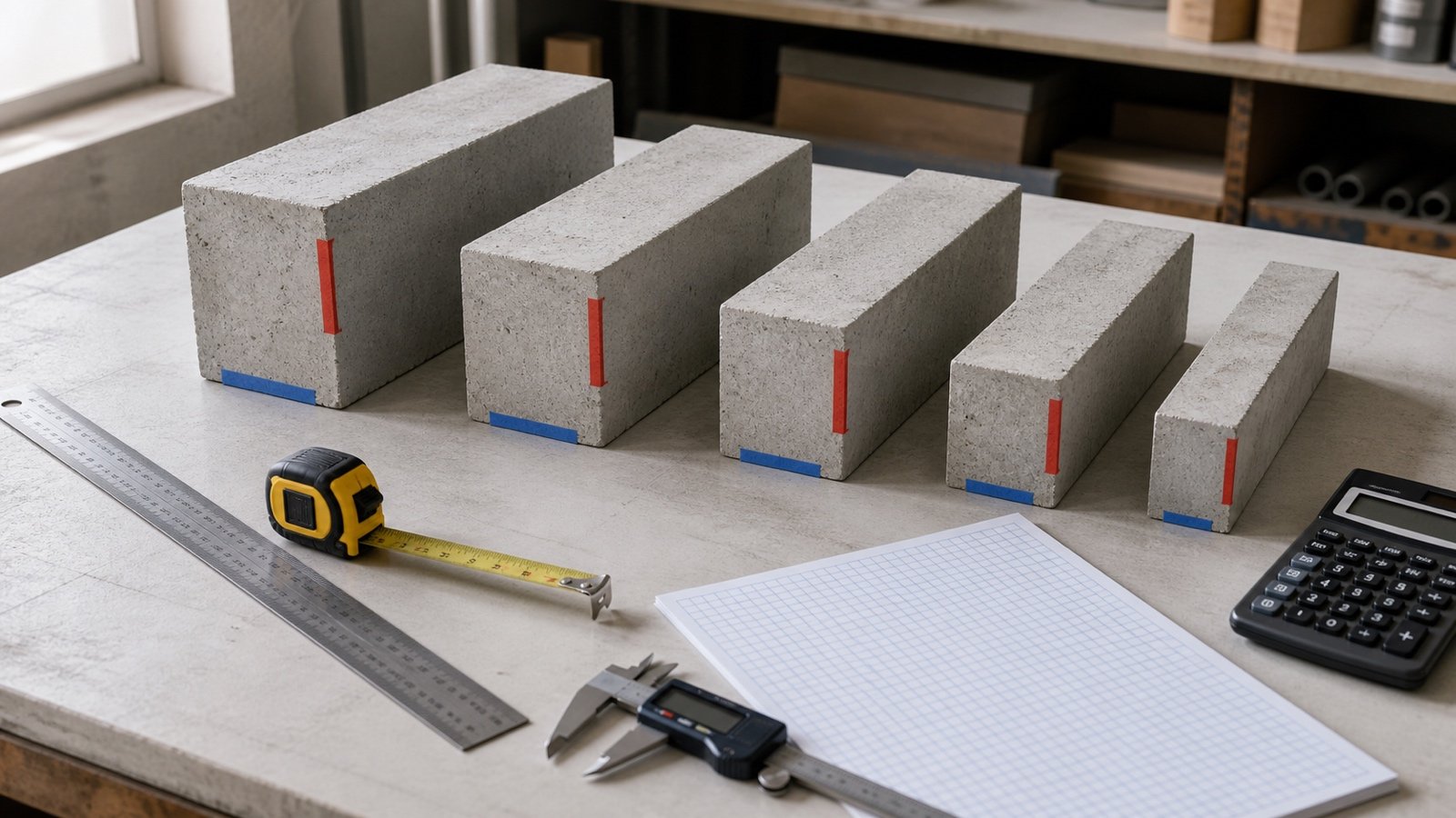
Use the average of the 2 end thicknesses when the thickness changes in a straight line across one constant cross-section and that cross-section is extruded unchanged along the wall length.
Linear tapered wall volume = length × height × (top thickness + base thickness) ÷ 2
Metric example: linear vertical taper
An 8 m long wall is 3 m high. Its horizontal thickness changes in a straight line from 300 mm at the base to 200 mm at the top.
- Convert the thicknesses: 300 mm = 0.30 m and 200 mm = 0.20 m.
- Average thickness: (0.30 + 0.20) ÷ 2 = 0.25 m.
- Wall volume: 8 × 3 × 0.25 = 6.00 m³.
- Maximum rectangular envelope: 8 × 3 × 0.30 = 7.20 m³.
- Envelope difference: 7.20 − 6.00 = 1.20 m³.
The formula stops applying when the taper is curved, stepped, twisted, or different along the wall length. A compound shape needs more sections, a checked model, or another method specified for the project.
How does a battered face change the measurement?
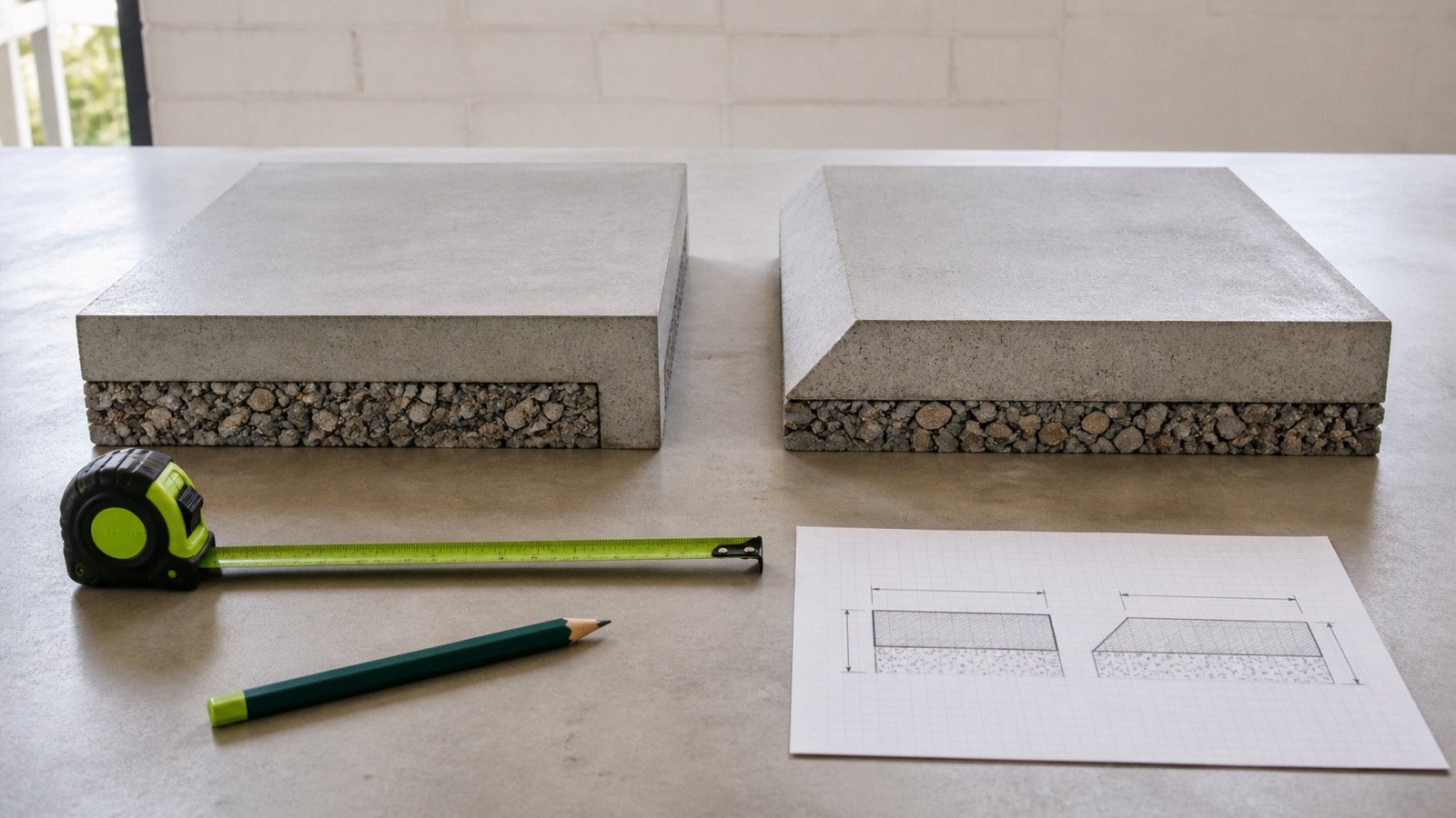
Trace the cross-section and label the direction of every dimension. A wall with one vertical face and one straight battered face forms a trapezoidal cross-section when its top and base horizontal thicknesses are known.
The linear-taper formula then applies to that cross-section. A thickness measured perpendicular to a sloping face cannot be inserted as a horizontal thickness. A dimension along the battered face cannot replace vertical height.
Record vertical height, horizontal thickness, and sloping-face length in separate fields. Convert between them only from a complete approved section with enough dimensions to define the triangle.
When both faces slope, confirm whether they remain parallel, converge, or move in different directions. An average of 2 labels cannot describe a twisting or nonlinear solid.
How do you calculate a concentric curved wall?
For a wall with constant radial thickness, constant height, and concentric inner and outer faces, multiply the centreline arc length by height and radial thickness.
Centreline arc length = angle in radians × centreline radius
Concentric curved wall volume = centreline arc length × height × radial thickness
Metric example: 90-degree curved wall
A 90-degree wall has a 5 m centreline radius, 3 m height, and 200 mm radial thickness.
- Convert the angle: 90 degrees = π ÷ 2 radians.
- Centreline arc length: (π ÷ 2) × 5 = 7.853982 m.
- Volume: 7.853982 × 3 × 0.20 = 4.712389 m³.
An annular-sector check with inner radius 4.90 m and outer radius 5.10 m gives the same result. Use the Concrete Wall Formwork Area guide for curved contact-face lengths because the inner and outer faces have different arc lengths.
The centreline shortcut cannot represent non-concentric faces, a changing radius, changing radial thickness, a spiral, or a wall whose height changes around the curve.
How should compound and modelled shapes be checked?
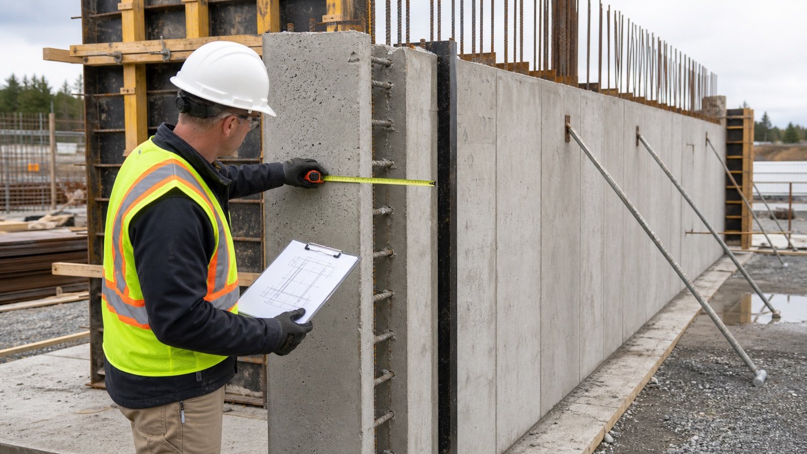
Keep one row per object or manually defined solid, then reconcile the model total with a second route. Check a simple wall, one special shape, and one intersection before accepting the full export.
| Check | Question | Evidence |
|---|---|---|
| Object limits | Where does the wall start and stop by level, grid, joint, or pour? | Plan, section, object ID, and revision |
| Joins | Did the software cut, merge, or retain intersecting concrete? | Section view and isolated object view |
| Openings | Are voids hosted, modelled separately, or absent? | Opening schedule and manual sample |
| Special shape | Does the model contain the step, pilaster, batter, taper, and curve shown? | Geometry view and dimension comparison |
| Units | Which length and volume units does the export use? | Project units and known-size fixture |
| Quantity owner | Which object owns shared concrete at an intersection? | Base, addition, and deduction ledger |
A visually complete model can still contain duplicate objects, wrong levels, hidden phases, inaccurate joins, or stale revisions. Keep the model version, export date, filters, object IDs, and manual check with the quantity record.
How does the method work in cubic yards?
A 24 ft long by 8 ft high wall is 10 in thick. One rectangular pilaster projects 4 in beyond one face, runs 24 in along the wall, and covers the full 8 ft height.
- Wall thickness: 10 ÷ 12 = 0.833333 ft.
- Base wall: 24 × 8 × 0.833333 = 160 ft³.
- Pilaster projection: 4 ÷ 12 = 0.333333 ft.
- Pilaster width: 24 ÷ 12 = 2 ft.
- Pilaster addition: 0.333333 × 2 × 8 = 5.333333 ft³.
- Combined measured volume: 160 + 5.333333 = 165.333333 ft³.
- Cubic yards: 165.333333 ÷ 27 = 6.123457 yd³.
NIST Handbook 44 (2026), Appendix C lists 27 ft³ in 1 yd³ and the cubic-metre relationships used for conversion. Keep the unrounded cubic-foot total until the final display or supplier step.
How does measured volume become an order quantity?
Keep the special-shape total in the measured column. Apply an approved planning allowance, supplier selling increment, delivery limit, and rounding rule in separate columns.
The ACI CCS-1(10) preview demonstrates compatible dimension conversion, volume calculation, cubic-foot to cubic-yard conversion, and the delivery information a concrete producer needs. Its slab example and allowance discussion do not set a universal factor for a wall project.
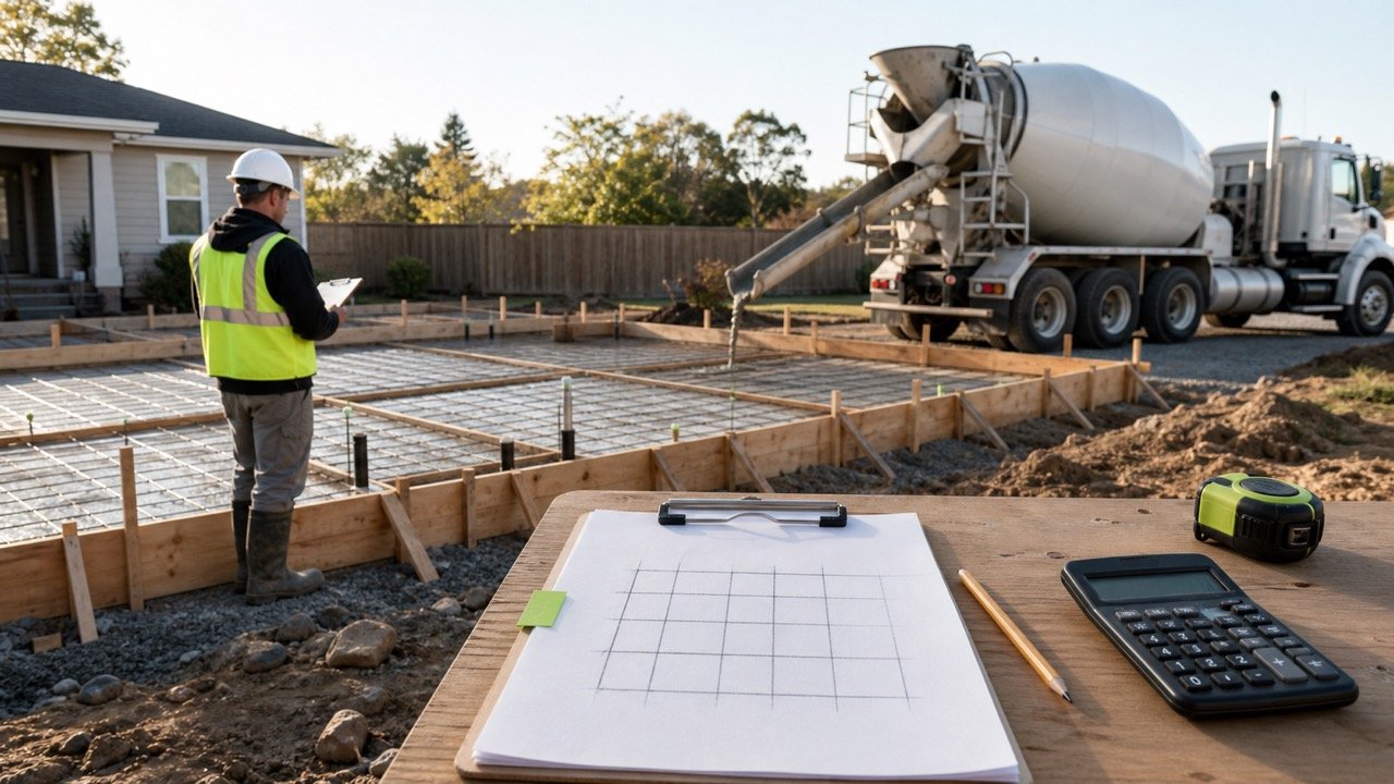
Use the Ready-Mix Concrete Calculator after the measured wall schedule is complete. Confirm the current mixture, selling unit, minimums, access, placement sequence, and commercial terms with the producer.
Common special-shape quantity mistakes
- Calculating the complete wall at the highest step and adding lower zones again.
- Adding a pilaster's full depth after the wall behind it has been counted.
- Using full base thickness for a linear taper.
- Mixing vertical height, sloping length, and perpendicular thickness.
- Using outer arc length for a centreline curved-wall formula.
- Applying the concentric formula to changing or offset curves.
- Letting wall joins or model object ownership hide duplicate concrete.
- Rounding every small solid before the schedule is added.
- Combining concrete volume with formwork area or reinforcement quantity.
- Applying a percentage to replace unresolved geometry.
- Using a superseded plan or section for one special shape.
- Treating an arithmetic fixture as an approved design detail.
What safety and scope limits apply?
This page measures accepted geometry. Structural wall design, reinforcement, form pressure, bracing, access, placement, inspection, and construction sequencing remain under the project documents and responsible qualified parties.
For covered United States construction work, OSHA 29 CFR 1926.703 requires formwork to support anticipated vertical and lateral loads and requires formwork drawings or plans, including revisions, to be available at the jobsite. A quantity schedule cannot approve the formwork or its use.
Do not climb, alter, load, or enter a formwork or reinforcement area to obtain a measurement outside the site's authorized access and safety process. Record an inaccessible or uncertain boundary as open.
Final special-shape check
- Freeze the drawing, model, RFI, and field-record revisions.
- Match each wall mark to its plan, section, details, and levels.
- Label every dimension direction and unit.
- Split steps and changing thicknesses at named boundaries.
- Assign parent walls, additions, deductions, and shared volume.
- Reproduce the special-shape arithmetic independently.
- Compare a model export with manual samples and inspect joins.
- Keep measured volume, allowance, supplier rounding, and order quantity separate.
- Use the Concrete Wall Takeoff guide for the full zone schedule and opening deductions.
- Use the Concrete Wall Thickness guide when a core dimension or direction remains unclear.
Return to the Concrete Planning hub for related tools. The calculation methodology explains units and rounding, and the corrections route accepts a source or arithmetic issue.
Sources and source scope
- ACI CCS-1(10) preview: compatible dimension conversion, concrete volume, cubic-yard conversion, and ordering information.
- HKIS BIM Measurement Information Requirements: wall marks, wall types, concrete strength, width, area, volume, and formwork fields.
- ArchSD BIM Guide for Cost Estimation, version 3.1: RC wall schedule fields, special-shape identification, dimensions, volume, mark, and element code.
- NIST Handbook 44 (2026), Appendix C: unit relationships.
- OSHA 29 CFR 1926.703: the stated US formwork safety and drawing-revision context.
Source scope: ACI supports the cited general quantity and ordering workflow. HKIS and ArchSD support quantity-record fields and wall-type context. NIST supports units, and OSHA supports the named US workplace boundary. The special-shape formulas are elementary geometry checked against the stated fixtures. These sources do not select the reader's wall geometry, approve a model, set contractual measurement, design formwork or reinforcement, or provide a universal allowance.
Review note: Saleem Sial owns the research and editorial record. Formula fixtures, source checks, build validation, and rendered QA form the internal publication gate. Waseem Sial, External Reviewer and Engineer, is listed for ongoing external review; no completed review date is claimed.