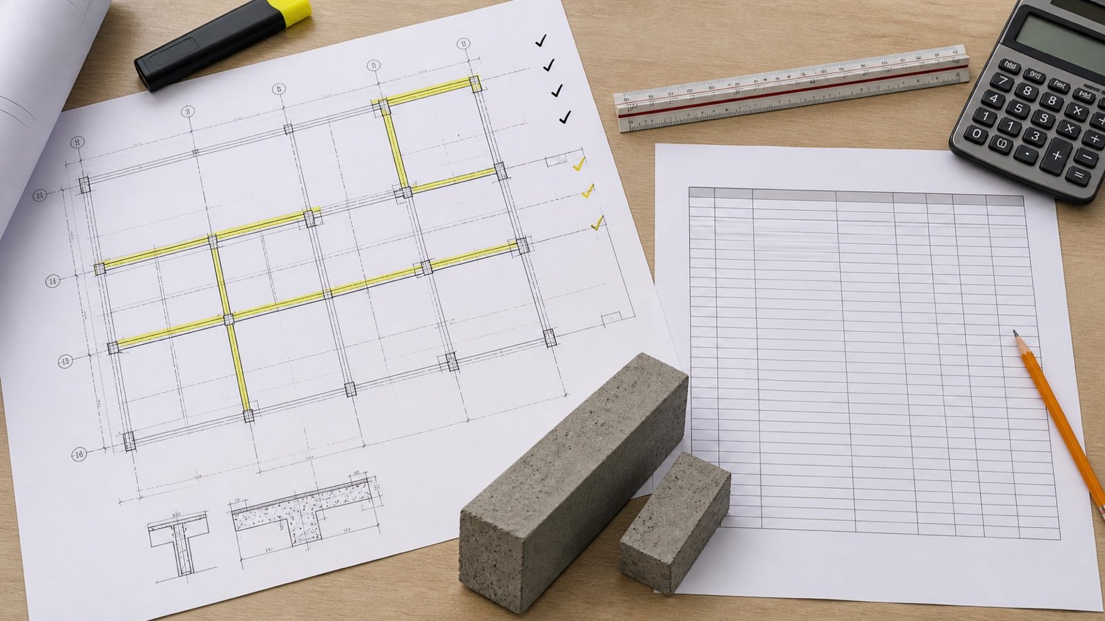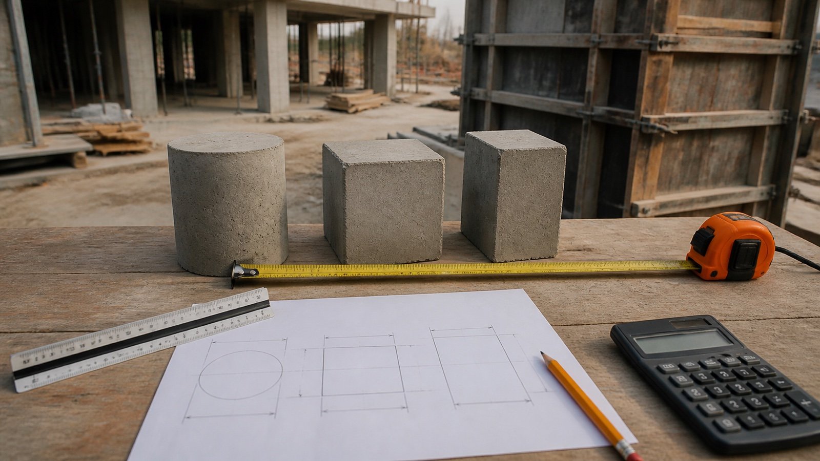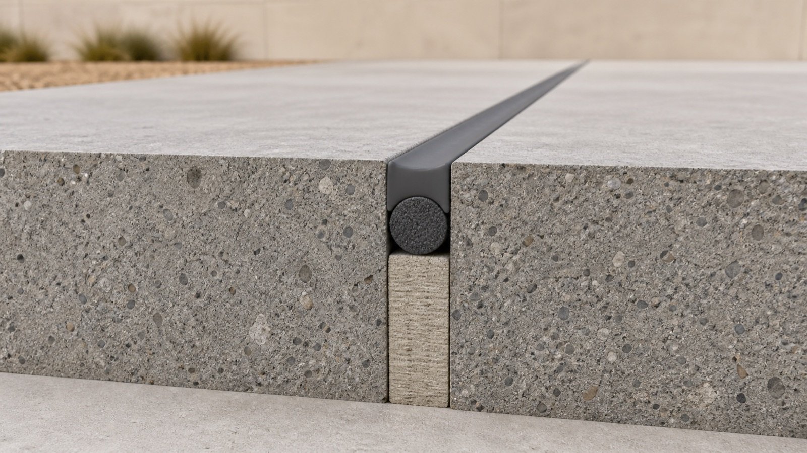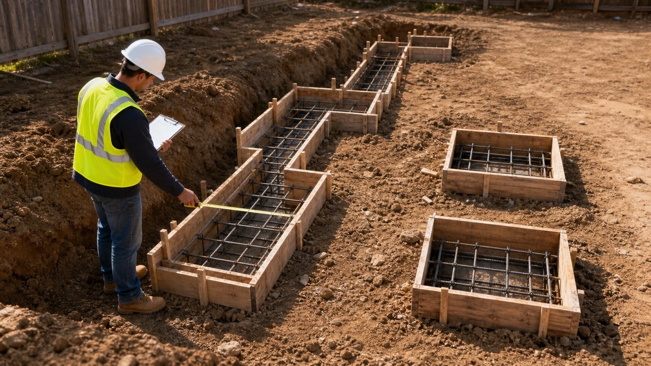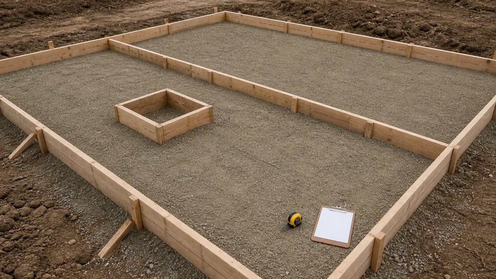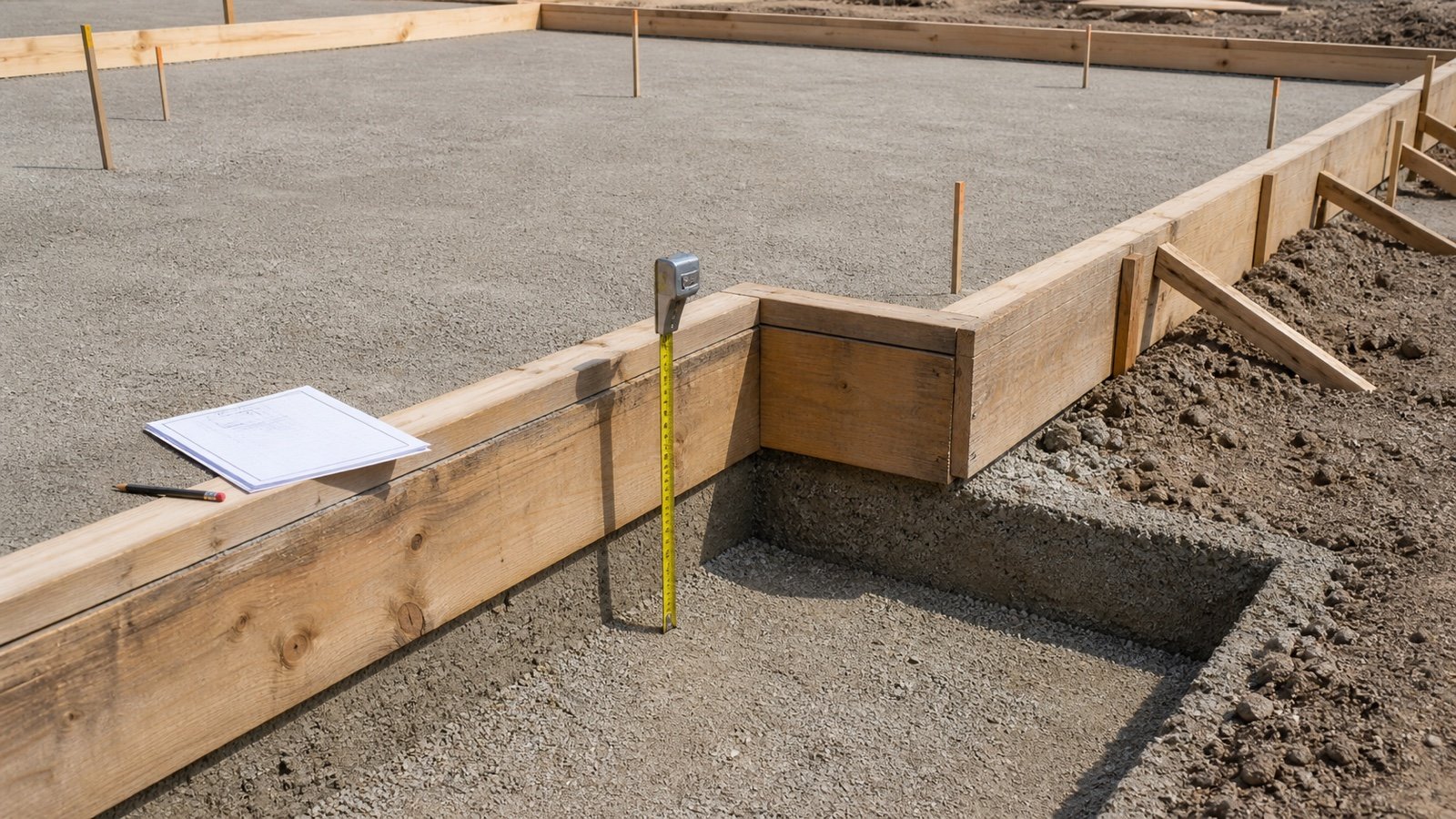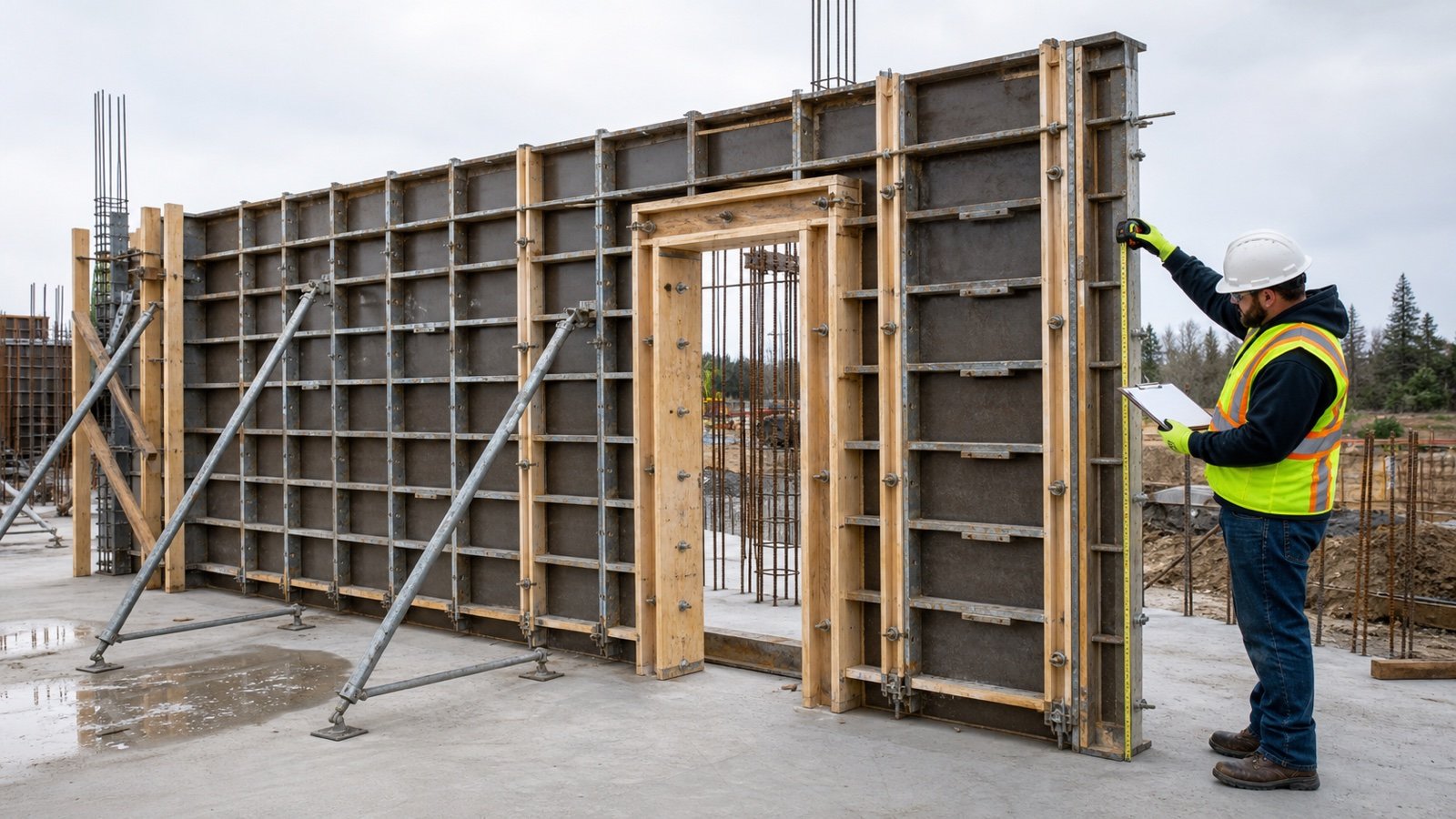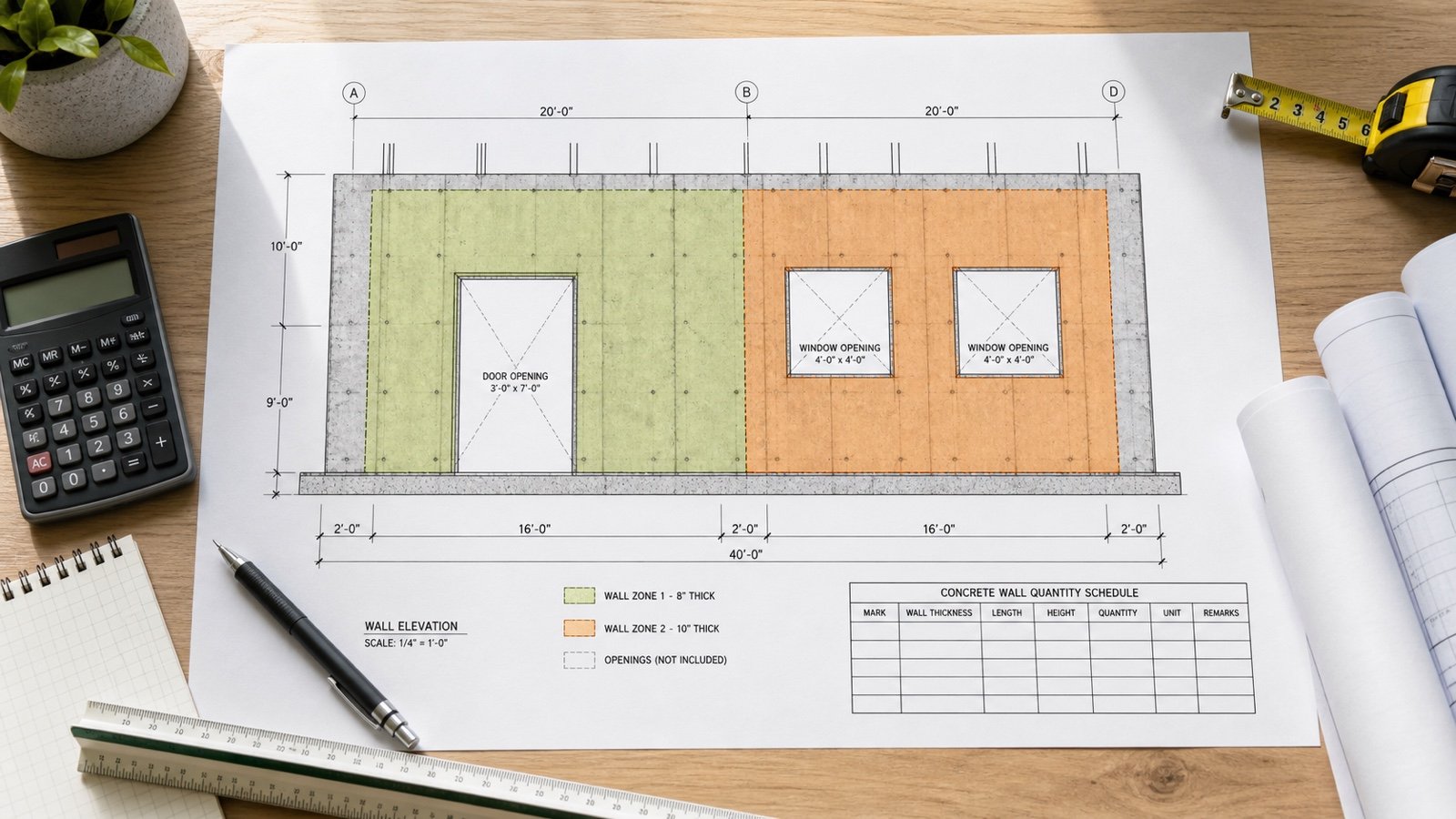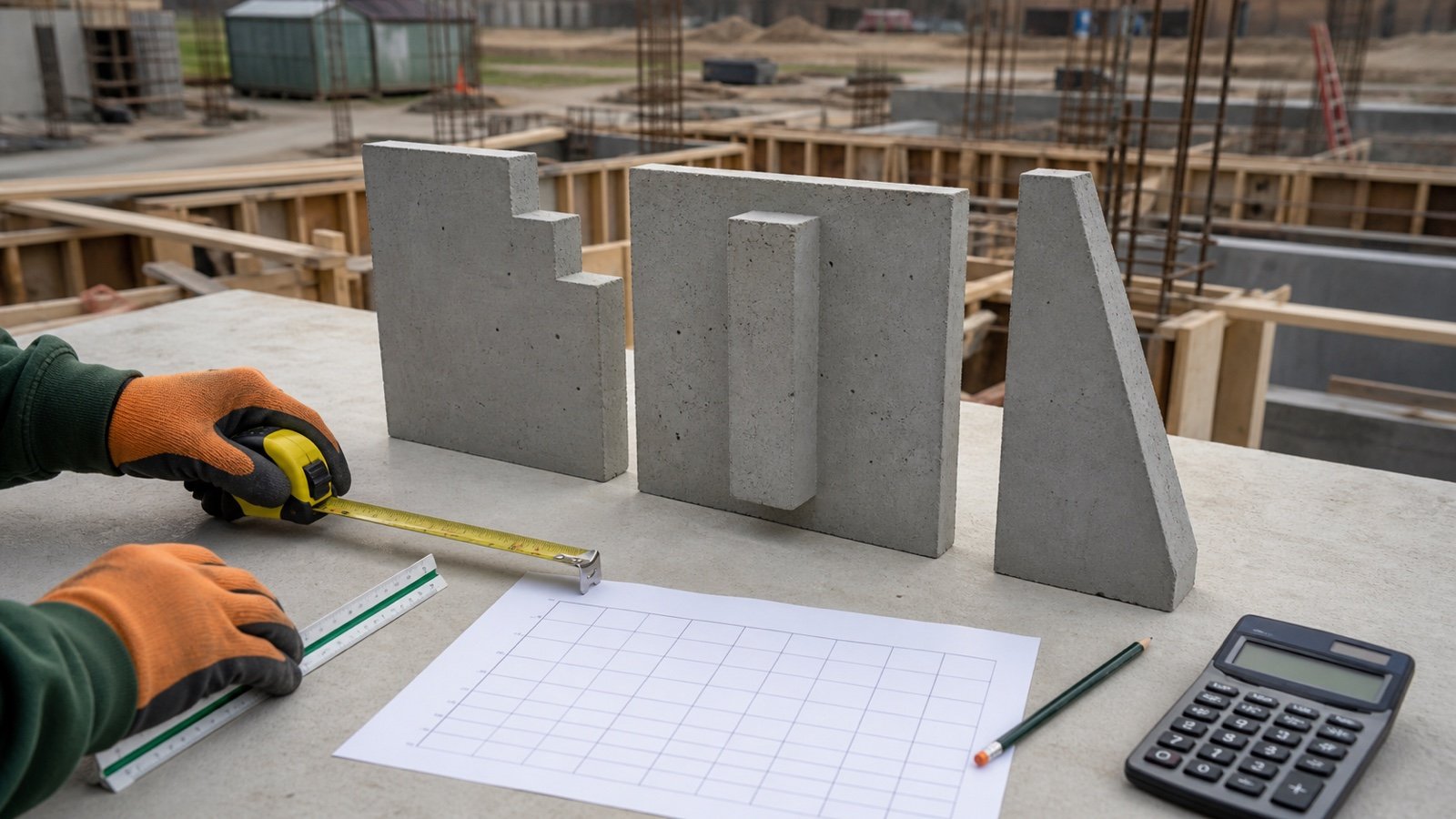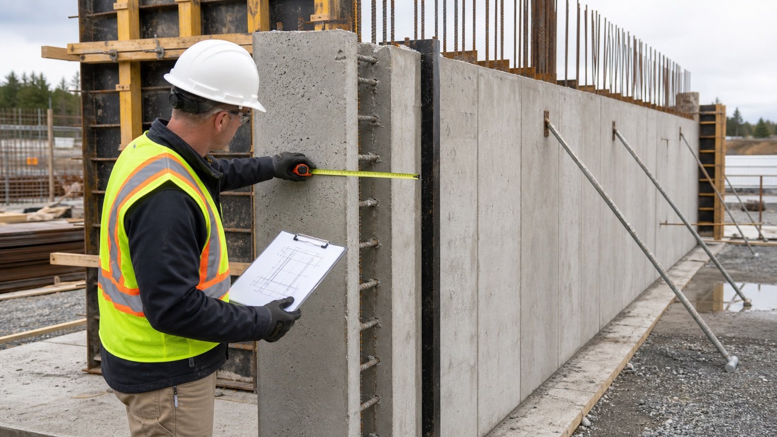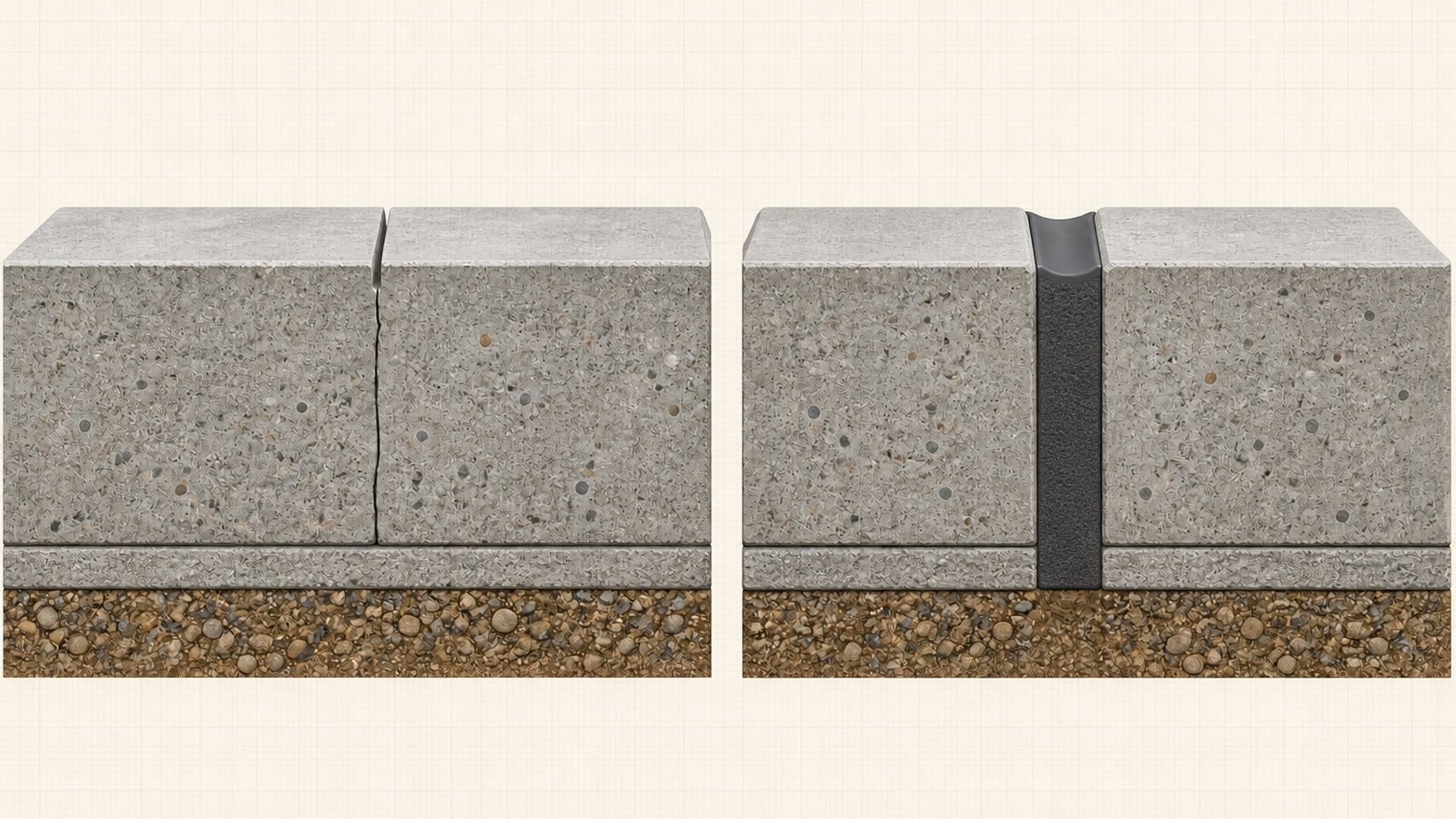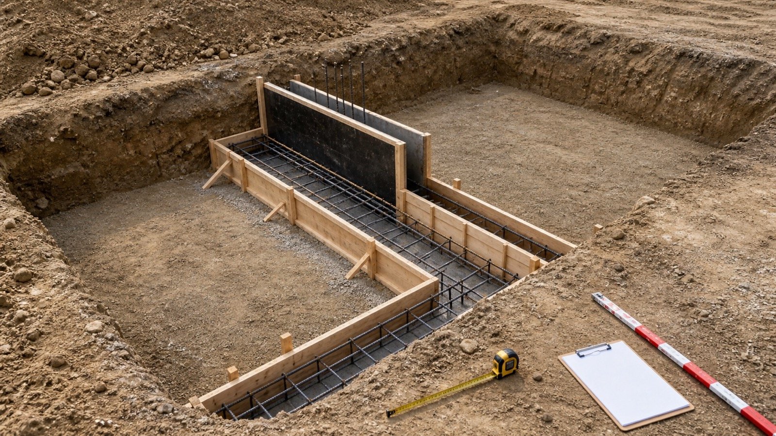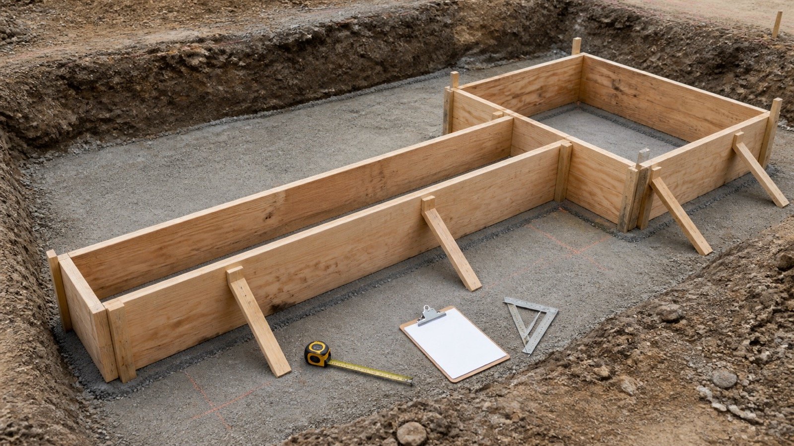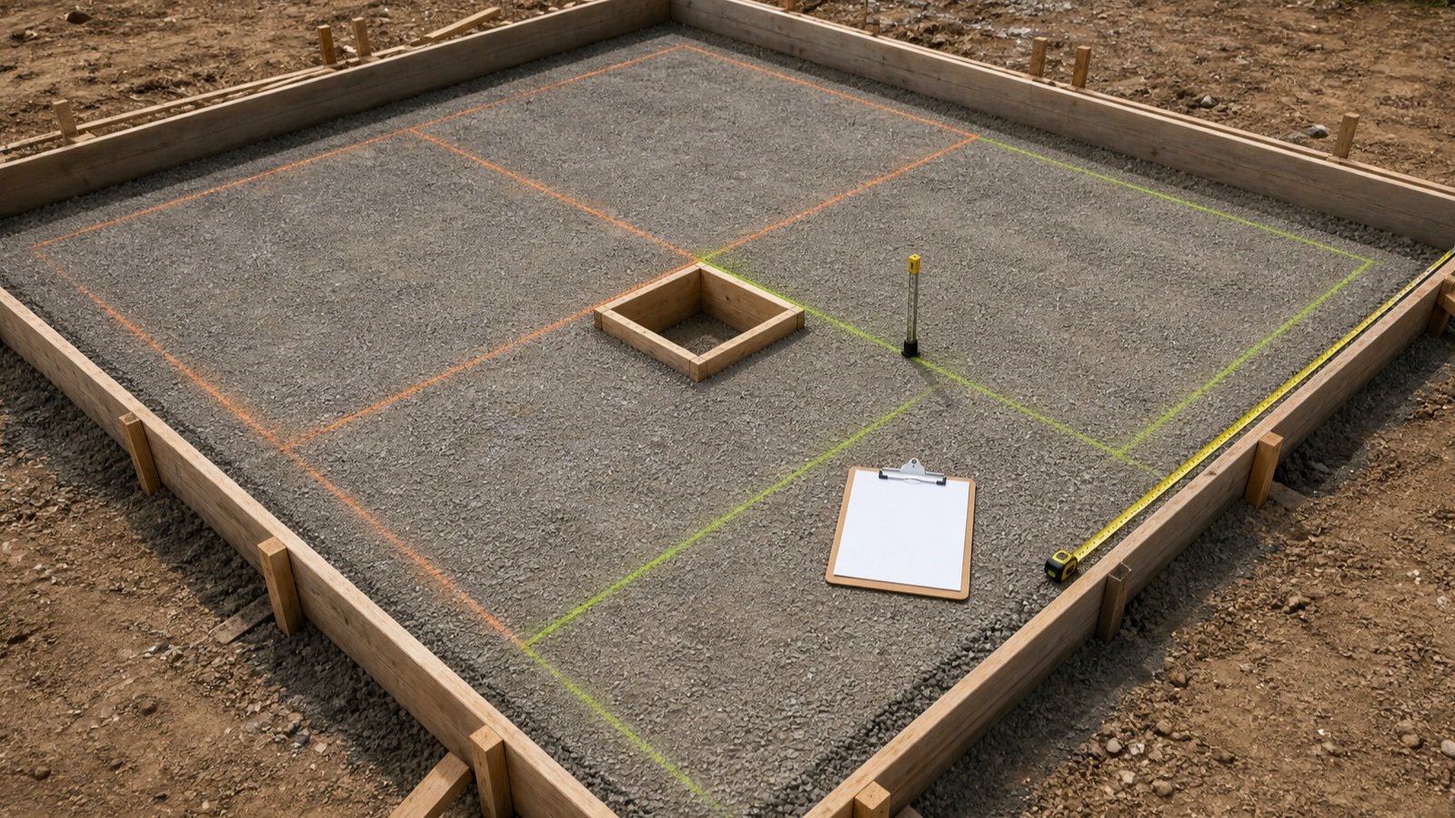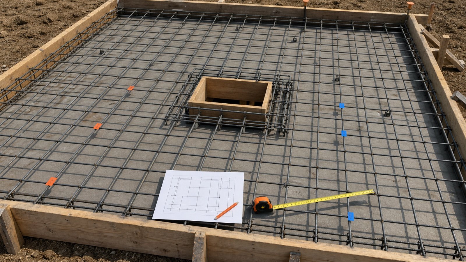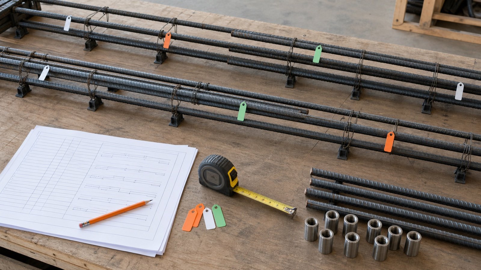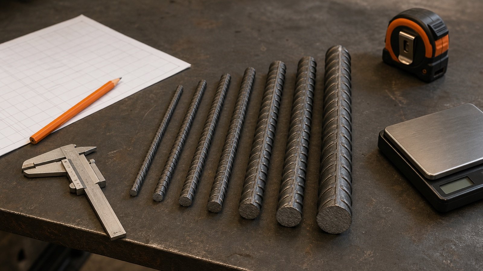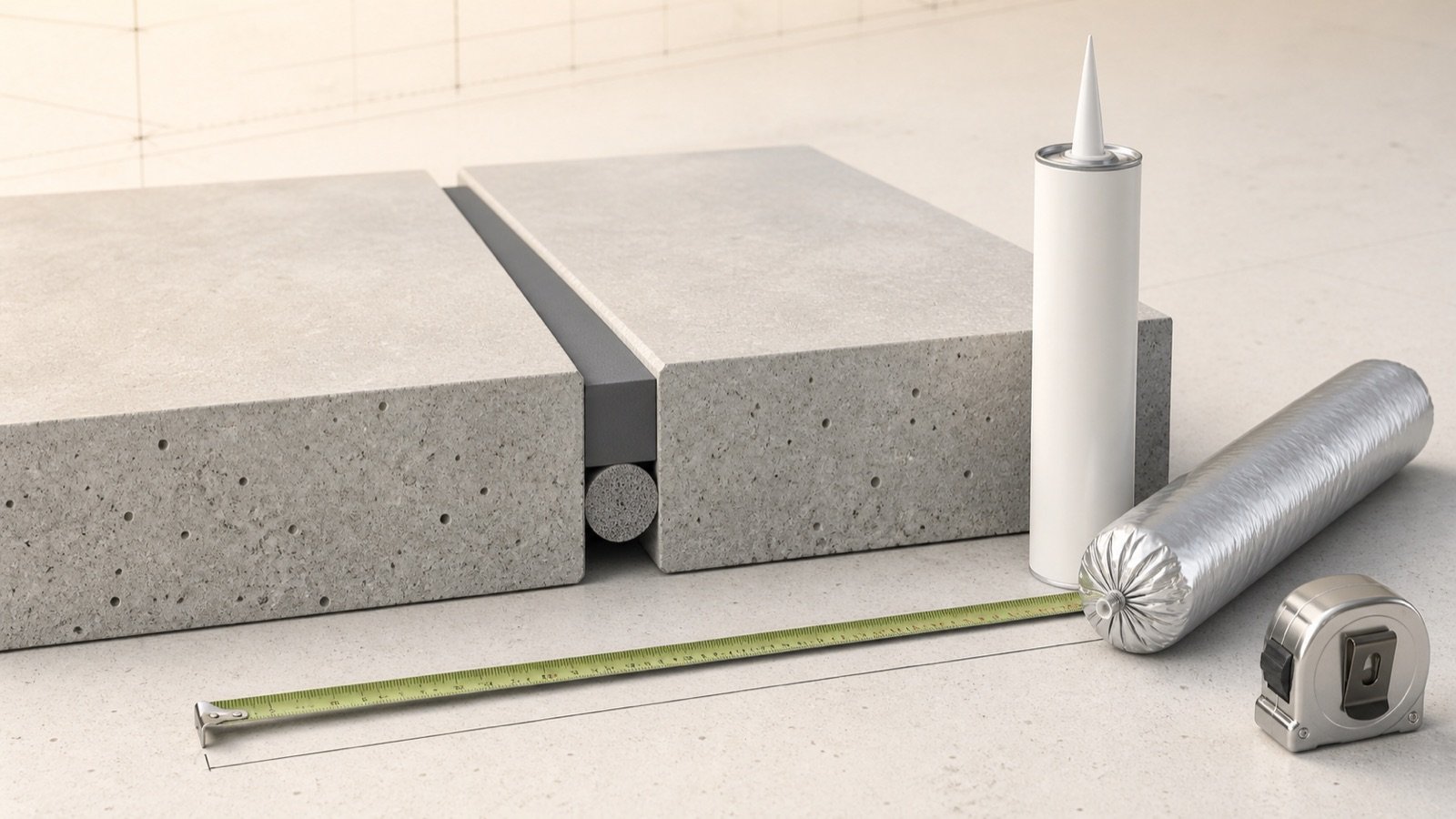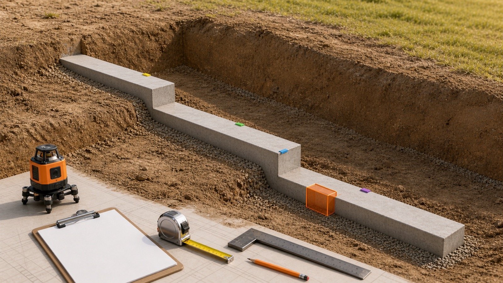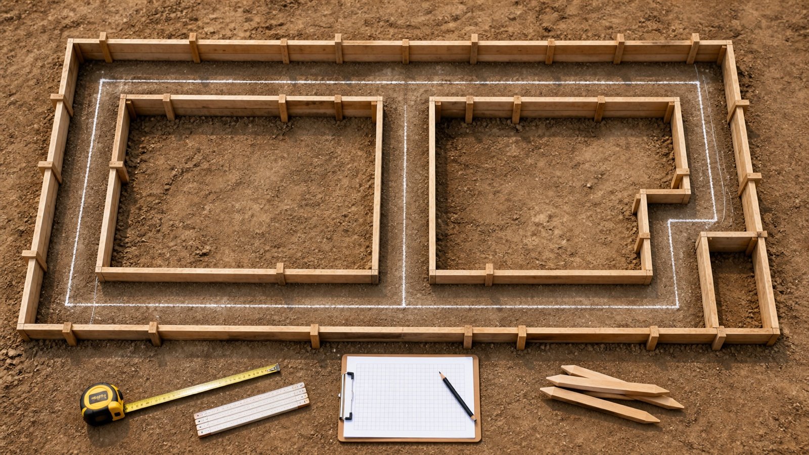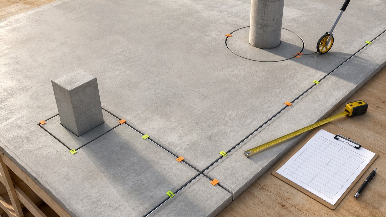
An expansion-joint takeoff begins with the route, not the sealant package. Trace every included joint from start to finish, measure its actual path and keep a record that another person can check against the drawings or site.
The total length becomes useful only after each segment is tied to its joint type, location, width, depth, system and purchasing unit. Separate those conditions before calculating sealant, filler, backing or fabricated transitions.
How do you measure the total length of expansion joints?
Measure each physical joint once along the route shown by the governing drawings or verified in the field. Add straight runs, perimeters and curves in one consistent unit, then split the total into groups whenever the approved joint profile or material system changes.
Kansas DOT Section 719 measures its specified expansion joints by linear foot along the joint centerline. Indiana DOT uses length along and parallel to the finished joint surface for one structural sealing system. These agency methods show why the measurement path must be stated. Your contract documents can define a different basis.
Record the physical route first. Add an approved allowance later in the quantity calculation, with its reason visible. Increasing the measured length and applying the same allowance again counts it twice.
Which documents and tools should you collect first?
Use the current drawing set, joint schedule, specifications, addenda, approved submittals and shop drawings that apply to the work. Record each revision and detail reference on the takeoff sheet so an older plan cannot silently control the quantity.
| Item | What it should establish | Check before use |
|---|---|---|
| Plans and reflected plans | Joint route, limits, intersections and location IDs | Drawing number, scale, issue date and revision |
| Sections and details | Joint type, plane, width, depth, blockout and adjoining assemblies | Every plan symbol points to the intended detail |
| Joint or sealant schedule | Material system and locations using each designation | Schedule agrees with the plan and specification |
| Approved submittal or shop drawing | Selected product, transitions, terminations and fabrication limits | Approval status and latest revision |
| Tape, folding rule or laser | Short straight runs and accessible checks | Suitable range, units and calibration check |
| Measuring wheel | Long accessible floor or pavement routes | Wheel tracks the joint path without cutting corners |
| Camera, sketch and marker | Location, condition, width changes and endpoints | Photos can be matched to a segment ID |
FHWA's bridge-joint inspection protocol lists a tape measure, folding rule, measuring wheel, thermometer, camera, marker and sketch pad. Its scope is bridge inspection, but the recordkeeping set is useful evidence for planning a field survey.
How should the joint route be traced on drawings?
Begin at one defined endpoint and assign a segment ID. Follow the joint until a termination, transition, intersection, change in plane, width change, material change or drawing break gives you a reason to start a new line.
- Mark the drawing and revision used.
- Trace only the joint types included in the work scope.
- Give each uninterrupted run a location ID.
- Write the start point, end point and detail reference.
- Measure or calculate the route length in the drawing's stated unit.
- Flag every unclear endpoint, crossing and change for field verification or a project clarification.
- Add the segment once to a check total, then assign it to the correct material group.
Use written dimensions where the project documents direct you to use them. A scaled takeoff needs a confirmed drawing scale and a known print or viewport calibration. If dimensions, scale and geometry disagree, record the conflict and use the project's clarification process.
How do you record each segment?
A segment record needs enough information to reproduce the takeoff. Length alone cannot show whether 2 lines use the same sealant, filler, backing or fabricated system.
| Field | Example entry | Why it matters |
|---|---|---|
| Segment ID | EJ-01-A | Connects drawings, photos, field marks and quantity lines |
| Location | Level 1, grid B/4 to B/8 | Prevents a similar run from being counted twice |
| Route and plane | Straight horizontal floor joint | Defines how length is measured and which installation method applies |
| Measured length | 42.00 ft | Preserves the unadjusted physical quantity |
| Joint designation | EJ-2 | Links the route to its governing detail and schedule |
| Width and depth basis | 1/2 in × 1/4 in sealant profile | Controls rectangular sealant volume when approved |
| Transition or termination | Floor-to-wall upturn at end | Can require separate fabrication, accessories or labor |
| Source and check | A-102 Rev 4; field check pending | Shows evidence and remaining uncertainty |
How do you measure straight runs and full perimeters?
Measure a straight run between its defined endpoints along the joint. For a full rectangular isolation joint, add all 4 sides or use twice the length plus twice the width.
Rectangle perimeter = 2 × length + 2 × width
A complete route around a 26 ft × 14 ft element is 2 × 26 + 2 × 14 = 80 ft. If the detail covers only 3 sides, add those 3 sides. The full-perimeter formula would overstate the work.
Measure around the joint centerline or other path required by the documents. Keep inside-edge, centerline and outside-edge measurements from being mixed in one group, especially around wide openings or tight corners.
How do you measure circular and curved joints?
Measure a curve along its actual joint path. A full circular joint uses its centerline diameter. A partial curve uses radius and included angle, or a calibrated measuring wheel or flexible tape when the shape is irregular.
Full circle length = π × centerline diameter
Arc length = 2 × π × centerline radius × angle ÷ 360
A quarter-circle with a 6 ft centerline radius is 2 × π × 6 × 90 ÷ 360 = 9.4248 ft, displayed as 9.42 ft. Measuring the straight chord between its endpoints would give about 8.49 ft and miss 0.94 ft of joint.
For an irregular site curve, mark short stations and record the measured path. Photos and a sketch should show where the curve begins and ends. Avoid rounding every small station before the segment total is calculated.
How are shared edges, intersections and crossings counted?
Count one physical joint run once, even when it forms the boundary of 2 slab areas. Summing the perimeter of every adjacent slab can count the same shared line twice.
At a cross or T-intersection, measure the continuous centerline routes through the intersection. Do not add a separate length merely because the lines meet. The detail may still require extra backing, sealant control, a splice or a fabricated transition at that point, so list the intersection as a separate count or note when required.
| Condition | Length treatment | Separate record |
|---|---|---|
| Shared boundary between 2 slab regions | Count the physical joint once | Keep both area references in the location note |
| T-intersection | Sum the 3 route legs to the meeting point | Record intersection treatment if specified |
| Cross intersection | Measure both continuous routes without duplicating overlap | Record splice, backing or sealant detail if required |
| Joint around a square column | Add the included sides or full perimeter | Count corners and terminations when separately supplied |
| Joint around a circular column | Use centerline circumference or field path | Record diameter basis and any splice |
When should one route become separate takeoff groups?
Start a new group when the approved profile, product or purchasing basis changes. Compatible lengths can be combined later; incompatible sections need their own volume, package, roll or fabrication calculation.
- joint designation or movement system;
- installed width or sealant depth;
- filler height, thickness or material;
- backer rod or bond-breaker requirement;
- sealant, primer or package size;
- horizontal, vertical, sloped or overhead application;
- traffic, water, chemical, fire or weather exposure;
- substrate or adjoining assembly;
- straight stock versus a factory transition or termination;
- new construction versus an existing-joint repair.
Sika Emseal's current checklist asks whether the gap width varies, whether dimensions were field measured, how the joint terminates and whether transitions occur. Its sales and takeoff terms also place verification of quantities, field conditions, joint size and project requirements with the purchaser.
How should changing width be checked in the field?
Record width at named stations instead of replacing the whole run with one casual average. Measure at endpoints, visible changes and enough intermediate positions to show the condition required by the selected system and project documents.
FHWA's bridge protocol measures joint opening at both ends and at midlength, records locations, and notes ambient temperature at the time. That is an inspection method for its bridge program, not a universal sampling rule. It shows the value of pairing dimensions with station and temperature when openings can move.
A field survey should also record edge spalls, misalignment, debris, moisture, old materials, blockouts, slope and access. The visible cavity depth can differ from the installed sealant depth because backing or tape controls the reservoir.
What changes at transitions and terminations?
A length total can pass through a floor-to-wall turn, curb, parapet, stair, column, roof edge or another joint system. Mark the exact point, direction and adjoining construction. A standard straight length alone may not purchase the required transition.
Sika states that factory-fabricated transitions, upturns, phased-construction pieces, cross-slope pieces, horizontal direction changes and terminations can be made from purchaser field measurements or approved shop drawings and priced separately. Use the selected system's order form and dimensional instructions.
Trace continuity through every relevant layer. A floor joint can connect to waterproofing, a wall joint, a fire barrier or a cover assembly. Request a coordinated detail when the drawings stop one system without showing the connection.
Worked example: straight runs, returns and column joints
A marked plan has 2 straight runs at 42 ft, 3 returns at 8 ft, one circular isolation joint around a 3 ft centerline diameter and 4 square columns with 2 ft × 2 ft full-perimeter joints.
- Straight runs: 2 × 42 = 84 ft.
- Returns: 3 × 8 = 24 ft.
- Circular route: π × 3 = 9.4248 ft.
- One square-column perimeter: 2 × 2 + 2 × 2 = 8 ft.
- Four square columns: 4 × 8 = 32 ft.
- Physical route total: 84 + 24 + 9.4248 + 32 = 149.4248 ft, displayed as 149.42 ft.
The 108 ft of straight runs and returns can form one group only if their approved profile and material system match. The 9.42 ft circular route and 32 ft of square-column perimeters stay separate until their details, widths, depths and products are confirmed.
| Group | Included route | Measured length | Next check |
|---|---|---|---|
| A | 2 straight runs plus 3 returns | 108.00 ft | Confirm one profile and system across every segment |
| B | 3 ft diameter circular isolation route | 9.42 ft | Confirm curved-system and splice instructions |
| C | 4 square-column perimeters | 32.00 ft | Confirm corners, terminations and profile |
| Check total | All included physical routes | 149.42 ft | Reconcile with marked plan and field scope |
How do you reconcile drawing and field quantities?
Preserve the original drawing takeoff, then create a dated field-revision record. Compare segment IDs rather than replacing one project total with another unexplained number.
| Check | Record | Action when different |
|---|---|---|
| Route exists | Shown, added, omitted or relocated | Link the change to an approved revision or clarification |
| Endpoints | Drawing and field start/stop locations | Update the affected segment length |
| Width and profile | Measured stations and approved detail | Split the group where the purchasing basis changes |
| Transitions | Type, location, direction and dimensions | Send required data through the system supplier process |
| Installed or usable stock | Accepted length and remaining packaged material | Revise the remaining order without erasing the baseline |
Record who measured the route, the date, units, drawing revision, instrument and accessible limitations. Keep photos and sketches under the same location IDs. A reviewer should be able to trace every adjustment back to evidence.
Which measurement mistakes change the quantity?
- Adding every slab perimeter and counting shared joints twice.
- Measuring a curve as a straight chord.
- Using full circumference when only part of a column perimeter is treated.
- Mixing inside-edge, centerline and outside-edge lengths.
- Scaling a drawing whose printed or displayed scale is wrong.
- Ignoring drawing revisions, addenda or approved shop drawings.
- Combining sections with different widths, depths, products or orientations.
- Using visible cavity depth as installed sealant depth.
- Leaving transitions and terminations inside a general straight-run note.
- Adding allowance to length and repeating it in the material calculation.
- Rounding every short segment before the group total.
- Replacing a drawing takeoff with a field total that has no segment record.
How does measured length become a material quantity?
Enter each compatible group in the Expansion Joint Calculator after the route length, approved installed sealant width, sealant depth, package volume and filler-roll basis are known. Keep the unadjusted measured length visible beside the result.
The Sealant Coverage per Tube chart checks rectangular package yield. The Expansion Joint Filler, Backer Rod and Sealant guide separates the material layers and purchasing records. Use the Control Joint vs Expansion Joint guide when a drawing label or existing groove needs classification before takeoff.
What limits and safety checks still apply?
This measurement guide does not locate or design expansion joints, set movement capacity, approve spacing, choose a product or certify a waterproofing, traffic, fire, seismic, bridge or structural system. Project drawings, specifications, approved submittals, current product data and responsible professionals control those decisions.
Field access can involve traffic, edges, roofs, lifts, wet surfaces and restricted areas. Cutting, routing or removal can expose silica, reinforcement, tendons, wiring, services or chemical residues. Use the site safety plan, access controls, scanning or clearance procedures, current safety data and qualified supervision required for the work.
For a current system quote or fabricated transition, send the required field measurements, sketches, photos and approved details to the selected manufacturer or supplier. The Concrete Planning hub lists the related calculators and guides.
Sources and source scope
- ASTM C1193-25 public page: current general scope for joint-sealant design, backing, primer, preparation, installation, exposure and manufacturer consultation.
- Sika Emseal Expansion Joint Checklist V9.0: total footage, varying gap widths, field measurement, temperatures, movement, transitions, terminations and construction information requested for selection or ordering.
- Sika Expansion Joints sales, quotation and takeoff terms: purchaser verification and field-measurement scope for quantities, joint conditions, transitions and terminations.
- Kansas DOT Section 719: one agency specification that measures expansion joints in linear feet along the centerline.
- Indiana DOT 724-B-145: one structural expansion-joint sealing specification measured along the plane of the finished joint surface.
- FHWA LTBP expansion-joint inspection protocol: joint identification, equipment, width stations, temperature, photos, sketches and condition records for its bridge program.
- Tremco Sealant Calculator: rectangular sealant quantity inputs of length, width and depth.
Source scope: The DOT and FHWA documents apply to their stated transportation work. Manufacturer documents support their named selection, ordering and calculation processes. ASTM supplies general joint-sealant context. The project documents and selected system control the actual measurement, design and purchase.
Review note: Saleem Sial owns the research and editorial record. Source checks, independent geometry fixtures, editorial review, build validation, link crawl, schema review and rendered QA form the internal publication gate. Waseem Sial, External Reviewer and Engineer, is listed for ongoing external review; no completed review date is claimed.