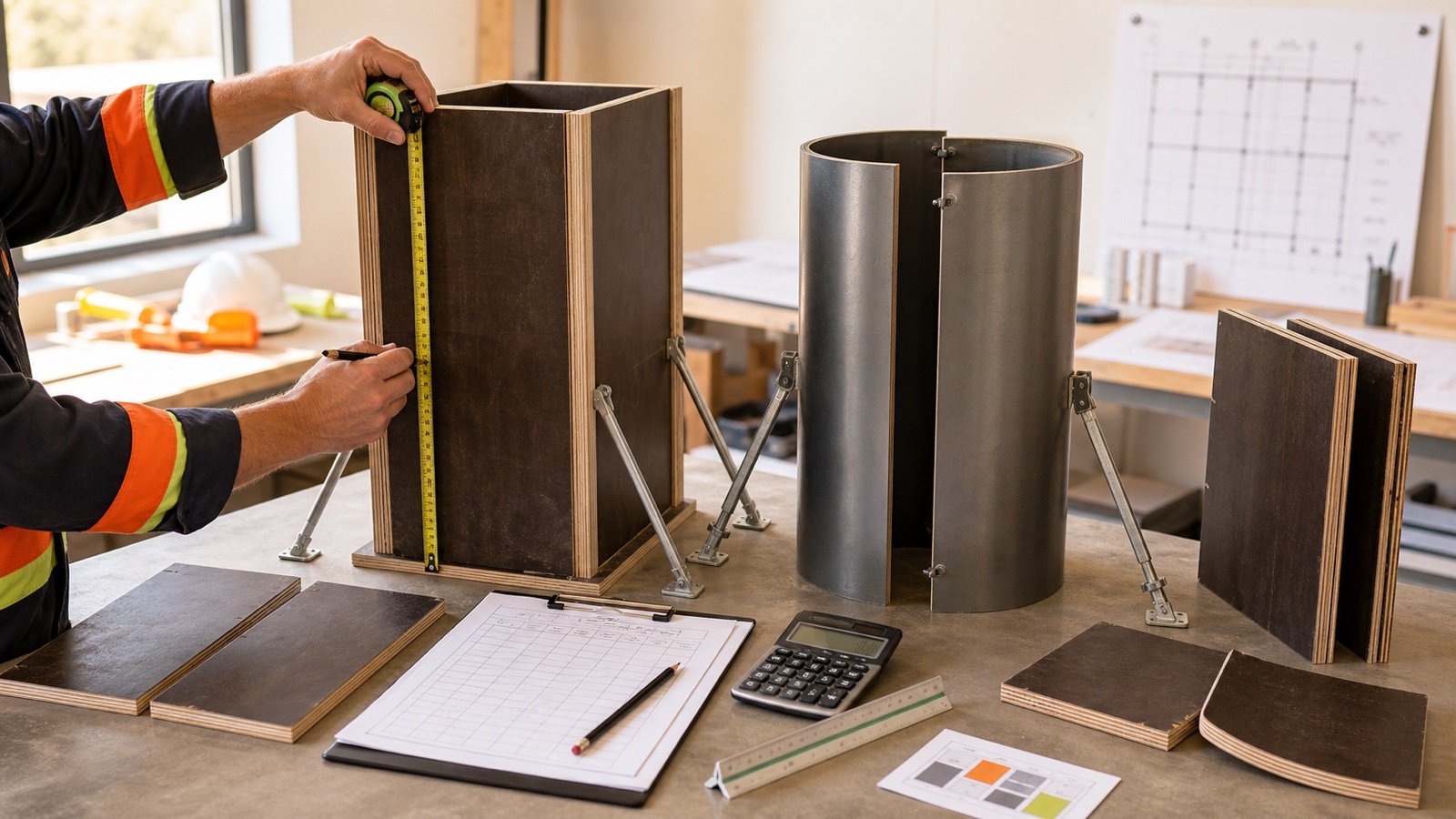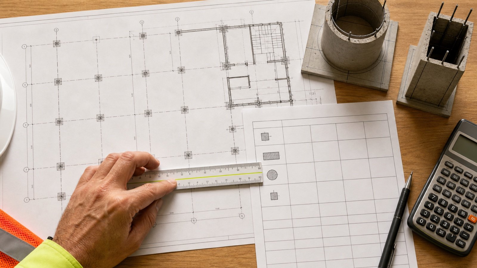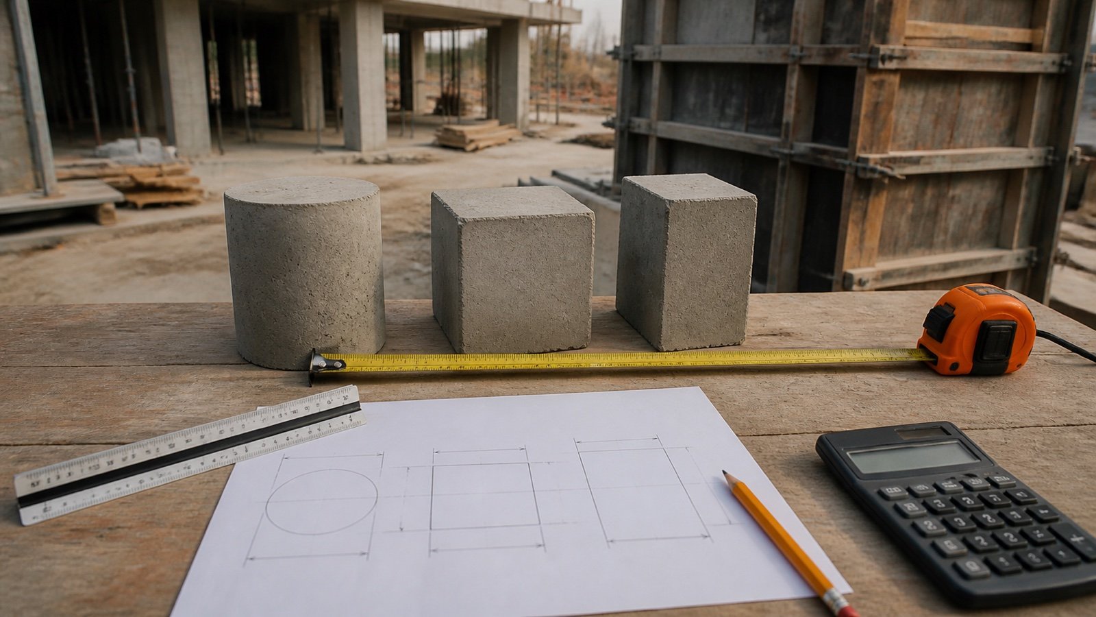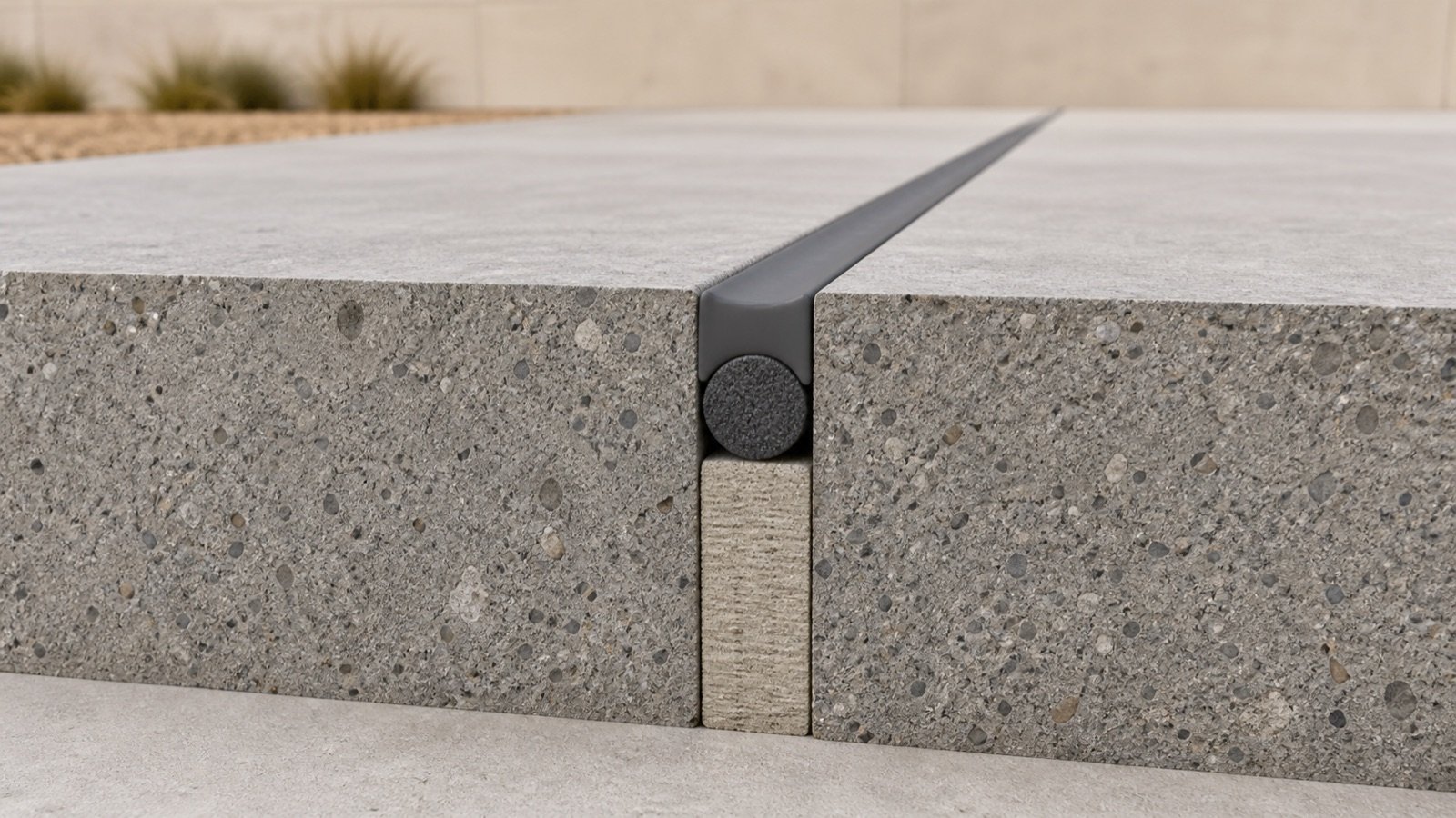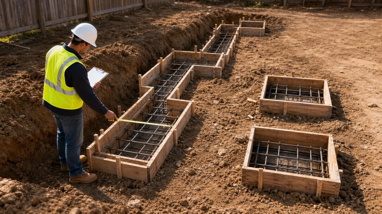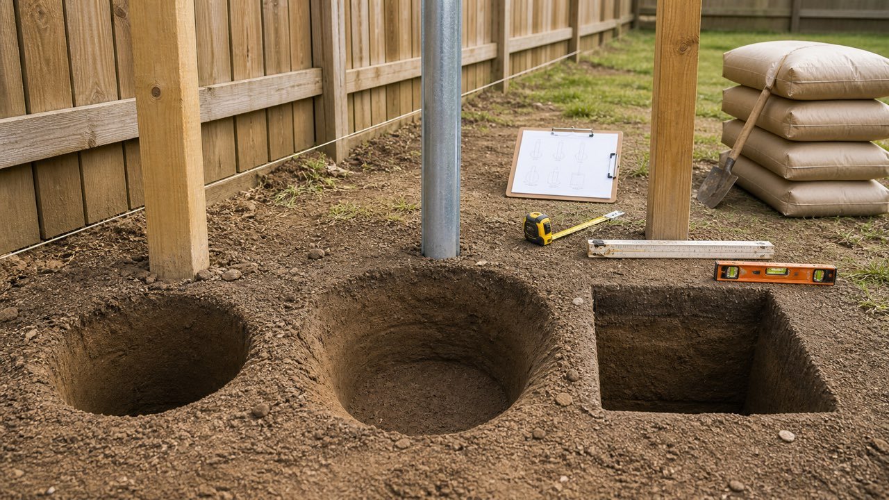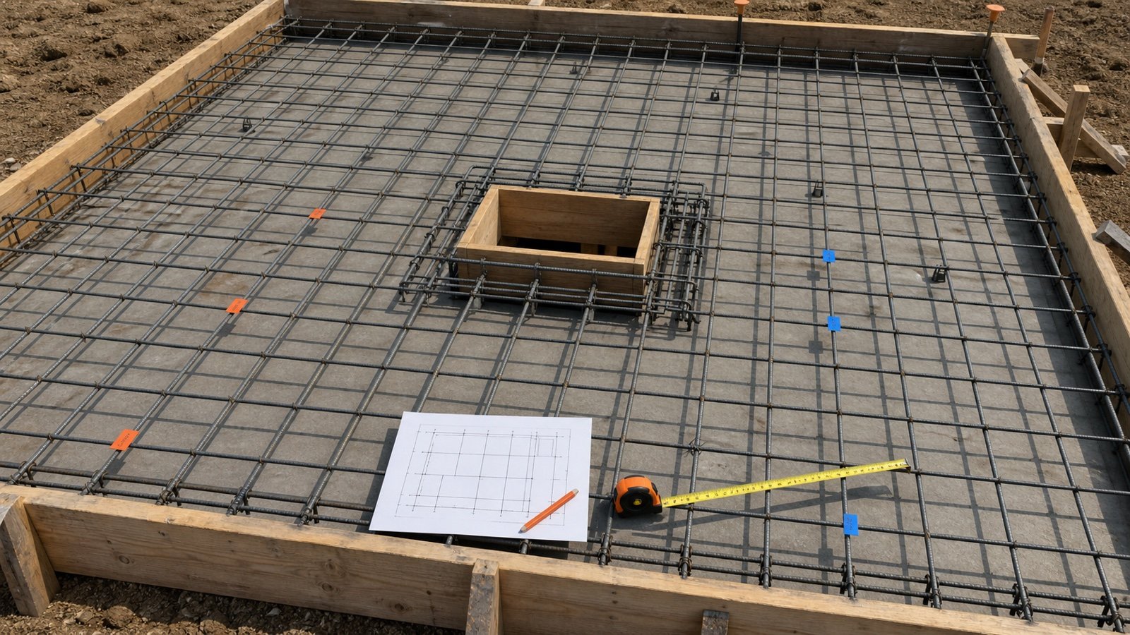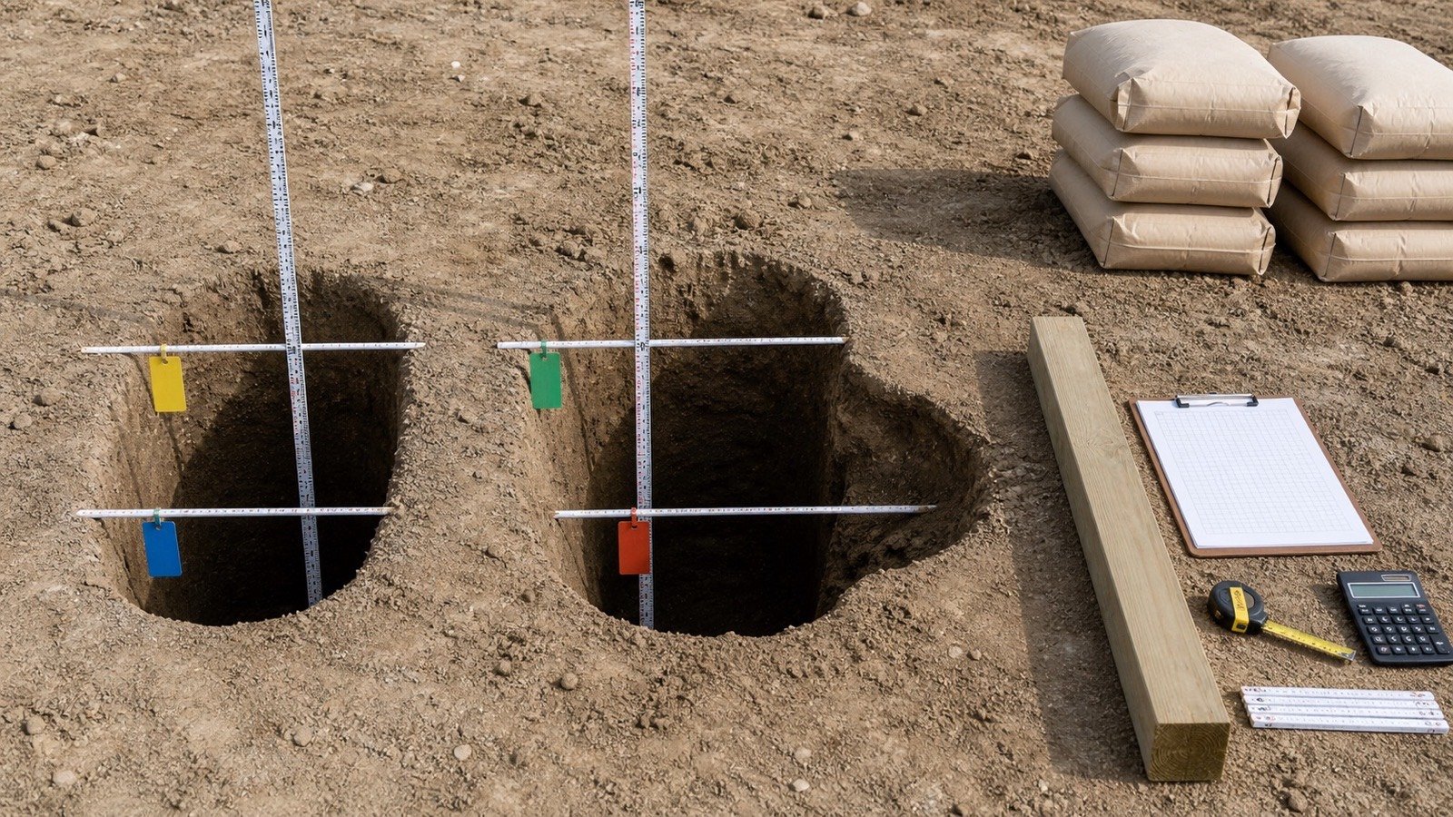
How do you calculate concrete for a special column shape?
Divide the approved geometry at every change in cross-section, direction, or ownership. Calculate each valid zone with one unit system, add the unrounded volumes, and check that no zone overlaps a footing, wall, beam, slab, or another column section.
Use the Concrete Column Calculator for each constant round, square, or rectangular shaft. Use the methods below for straight tapers, stepped pedestals, simple capitals, attached projections, and equal corner chamfers.
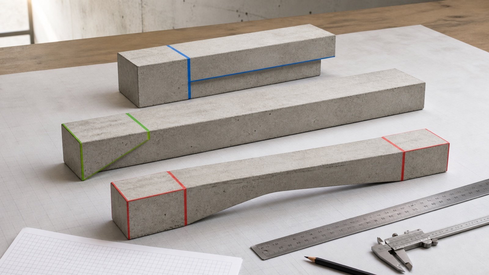
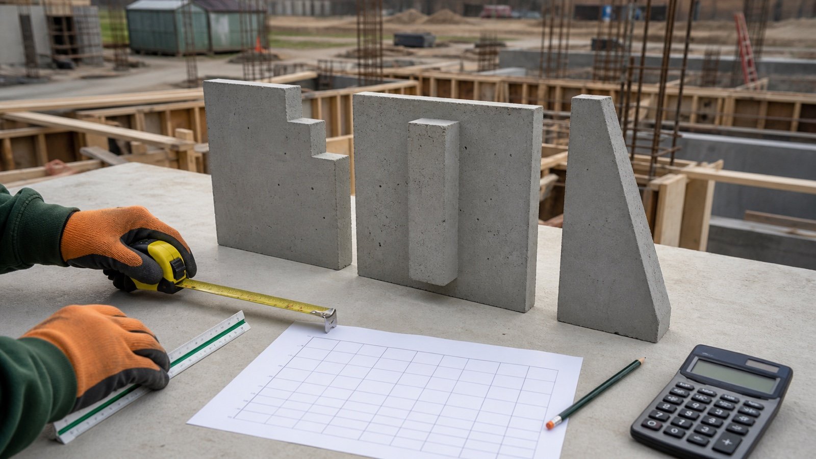
A straight taper, curved flare, offset transition, and stepped change can share the same end sizes while containing different volumes. Record the actual profile from current drawings, details, schedules, model sections, or accepted field measurements.
Which method matches the column shape?
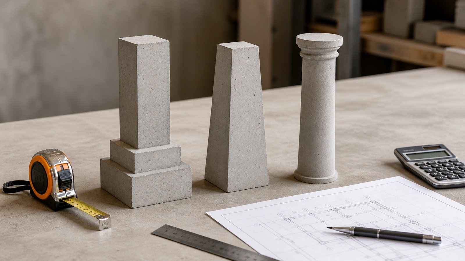
Choose the method from the physical boundary, not from the element name. A "capital" may be a rectangular block, a straight-sided frustum, a curved mushroom profile, or a slab zone assigned under another measurement rule.
| Observed geometry | Quantity method | Required record |
|---|---|---|
| Constant rectangular step or pedestal | Rectangular prism | Length, width, height, and shared planes |
| Several constant steps | Sum non-overlapping prisms | Dimensions and height of every step |
| Width and depth change linearly | Prismoidal formula | Lower, middle, upper sections and height |
| Round diameter changes along a straight line | Conical-frustum formula | Lower and upper diameter plus height |
| Constant shaft with equal corner chamfers | Gross prism minus triangular corner prisms | Gross sides, chamfer legs, and height |
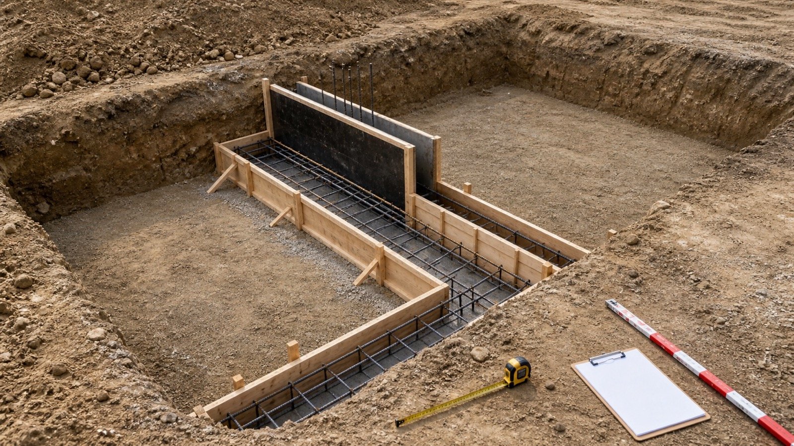
| Constant projection beyond an already measured wall | Projection-only prism, when the adopted rules give the wall the overlap | Projection, exposed width, height, and ownership rule |
| Curve, twist, offset, unequal transition, or changing chamfer | Approved section integration or audited model volume | Profiles, stations, model revision, and checker |
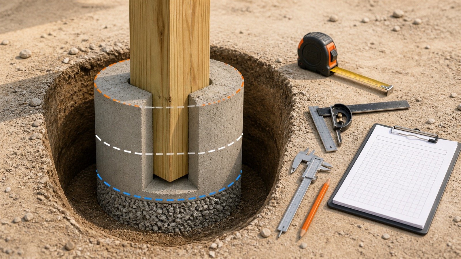
Where should the shaft, pedestal, and capital start and stop?
Set one lower and one upper plane for every zone. Adjacent zones meet at a shared plane and neither zone passes through it.
| Zone | Typical lower record | Typical upper record |
|---|---|---|
| Footing | Accepted excavation or blinding boundary | Defined footing or pedestal interface |
| Pedestal | Top of footing or stated base plane | Start of shaft or taper |
| Shaft | Top of pedestal or lower joint plane | Start of capital, beam, or slab boundary |
| Capital | Plane where flare begins | Defined slab, drop, or capital limit |
The project measurement method controls the final ownership. RICS NRM 2 includes columns and attached columns within in-situ vertical work measured in cubic metres, but a contract can assign intersections differently. Record the adopted rule and revision beside the calculation.
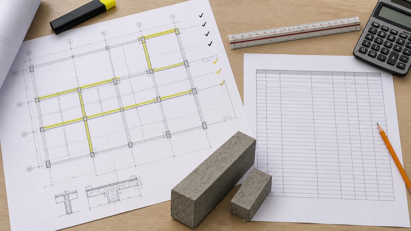
Use the Concrete Column Quantity Takeoff to prepare the mark, level, detail, revision, and boundary schedule before calculating a special zone.
How do you calculate a stepped concrete pedestal?
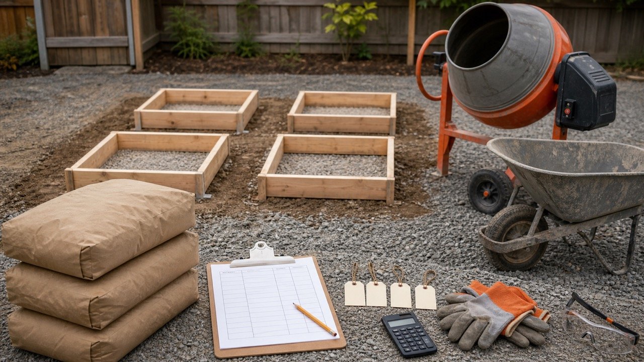
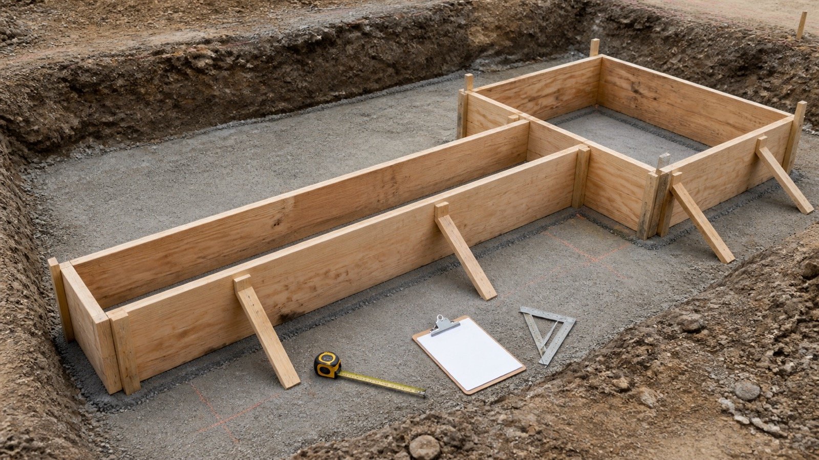
Calculate each constant rectangular step as length × width × height, then add the non-overlapping values. Start the shaft at the top of the pedestal when the pedestal volume already extends to that plane.
Stepped volume = Σ(length × width × height) for each non-overlapping step
Example: a pedestal measures 0.80 m × 0.80 m × 0.45 m. A 0.40 m × 0.40 m shaft rises 3.00 m from the pedestal top.
- Pedestal: 0.80 × 0.80 × 0.45 = 0.288 m³.
- Shaft: 0.40 × 0.40 × 3.00 = 0.480 m³.
- Combined measured volume: 0.288 + 0.480 = 0.768 m³.
Extending the 3.00 m shaft down through the 0.45 m pedestal would add 0.072 m³ that the pedestal line already owns. Check shared height planes before applying any allowance.
How do you calculate a rectangular tapered column?
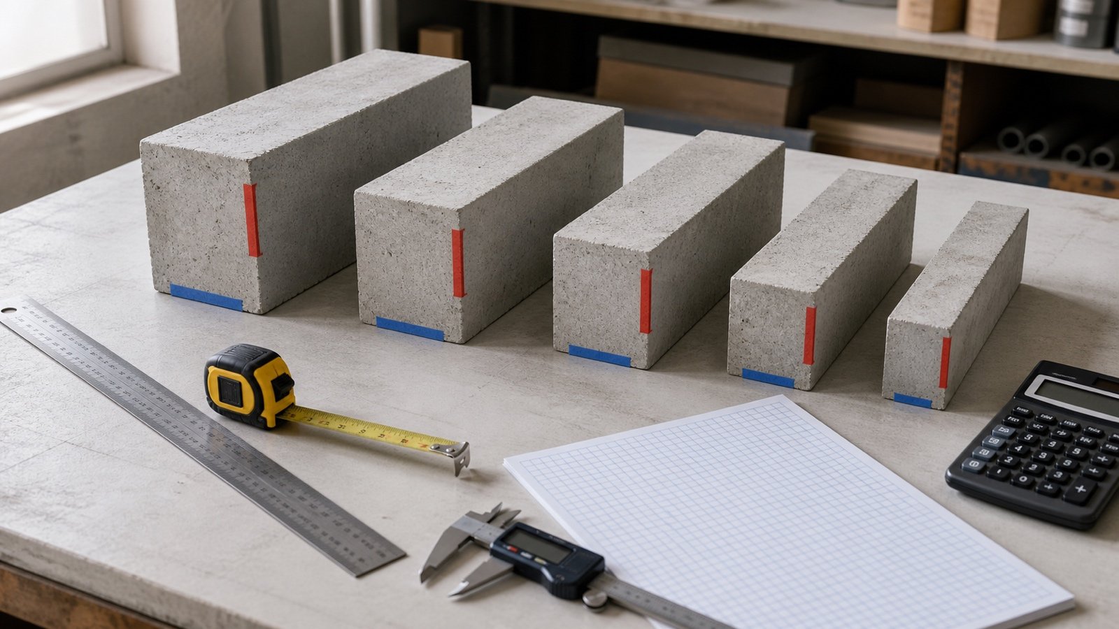
Use the prismoidal formula when width and depth each change linearly between the lower and upper planes. Measure the actual mid-height section; it controls the cross-section curve inside the formula.
V = H ÷ 6 × (A₁ + 4Aₘ + A₂)
Here, A₁ is the lower area, Aₘ is the area at half height, and A₂ is the upper area. All 3 sections must be perpendicular to the same height axis.
Example: a 3.00 m taper changes from 0.60 m × 0.40 m at the base to 0.40 m × 0.30 m at the top. Both dimensions change linearly, so the half-height section is 0.50 m × 0.35 m.
- Lower area: 0.60 × 0.40 = 0.240 m².
- Mid-height area: 0.50 × 0.35 = 0.175 m².
- Upper area: 0.40 × 0.30 = 0.120 m².
- Volume: 3.00 ÷ 6 × (0.240 + 4 × 0.175 + 0.120) = 0.530 m³.
Why can averaging the end areas give the wrong taper volume?
Endpoint averaging gives 3.00 × (0.240 + 0.120) ÷ 2 = 0.540 m³ for the same taper. The result is 0.010 m³ high because width and depth change together, which makes cross-section area vary quadratically through the height.
The average-end-area method is exact when area itself changes linearly, including a wedge whose one cross-section dimension stays constant while the other changes linearly. Confirm the geometry before using that shortcut.
How do you calculate a round tapered shaft?
Use the conical-frustum formula for a straight round taper whose centreline stays fixed and whose radius changes linearly. Use clear concrete diameters at the 2 end planes.
V = π × H ÷ 12 × (D₁² + D₁D₂ + D₂²)
Example: lower diameter 0.60 m, upper diameter 0.40 m, and height 2.40 m.
V = π × 2.40 ÷ 12 × (0.60² + 0.60 × 0.40 + 0.40²) = 0.477522 m³.
A curved bell, entasis, stepped reduction, or offset top needs another profile. Several sections can approximate a curve for early planning, but the interval and error basis must be visible and the final order should use approved geometry.
How should a column capital be measured?
Separate the capital at the plane where its cross-section begins to change. Calculate a simple block as a prism, a straight centrally aligned flare as a valid frustum or prismoid, and a curved mushroom capital from approved sections or an audited model.
| Capital condition | Check before calculation |
|---|---|
| Rectangular block above shaft | Deduct the shaft overlap if the block line is meant to include only added concrete |
| Straight rectangular flare | Confirm lower, middle, and upper sections plus centred or offset geometry |
| Round straight flare | Confirm both diameters and vertical height |
| Curved mushroom capital | Use approved profiles and enough stations to meet the required accuracy |
| Capital enters slab or drop panel | Assign the shared volume once under the adopted measurement rule |
A model category name cannot settle boundary ownership. Inspect sections through the joint and compare the model volume with at least one manual section calculation.
How do you handle an attached column at a wall?
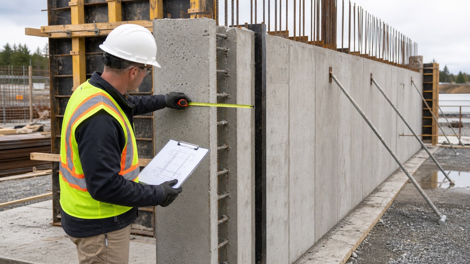
Record which element owns the shared concrete. If the wall volume already includes the full wall thickness, an attached constant rectangular column addition can use only the projection beyond the wall face.
Added projection volume = projection beyond wall × exposed width × height
Example: an attached feature projects 0.20 m beyond the measured wall face, spans 0.60 m along the wall, and rises 3.00 m. The added volume is 0.20 × 0.60 × 3.00 = 0.360 m³ when the wall line already owns the overlap.
If the adopted method measures the full attached column separately, apply that rule and change the wall boundary to prevent duplication. Keep the same ownership decision for drawings, model quantities, tender records, and change comparisons.
How do chamfers change concrete column volume?
Deduct each constant chamfer from the gross cross-section. A 45-degree corner chamfer with equal leg length c removes a triangular area of c² ÷ 2 at each corner.
Net volume = (gross area - number of corners × c² ÷ 2) × height
Example: a 0.50 m × 0.50 m shaft is 3.00 m high and has four 50 mm equal-leg chamfers.
- Gross volume: 0.50 × 0.50 × 3.00 = 0.750 m³.
- Chamfer deduction: 4 × (0.05 × 0.05 ÷ 2) × 3.00 = 0.015 m³.
- Net geometric volume: 0.735 m³.
Use the actual chamfer section. A rounded arris, unequal bevel, changing chamfer, or decorative reveal needs its own geometry. Check whether the adopted formal measurement rules require or prohibit a small deduction before changing a bill quantity.
Worked imperial example: pedestal and shaft
A 3 ft × 3 ft pedestal is 1.5 ft high. An 18 in × 18 in shaft rises 8 ft from the pedestal top.
- Pedestal: 3 × 3 × 1.5 = 13.5 ft³.
- Convert shaft sides: 18 in ÷ 12 = 1.5 ft.
- Shaft: 1.5 × 1.5 × 8 = 18.0 ft³.
- Total: 13.5 + 18.0 = 31.5 ft³.
- Cubic yards: 31.5 ÷ 27 = 1.166667 yd³.
NIST Handbook 44 lists 27 ft³ in 1 yd³. Keep 31.5 ft³ as the measured result in the calculation record, then apply project allowance and supplier rounding as separate steps.
How do you audit a BIM or CAD volume?
Check the model category, phase, design option, join behavior, cut geometry, voids, units, and revision before accepting its volume. Then compare it with a manual result for one representative member.
- Open a section through every cross-section change.
- Confirm the lower and upper planes for pedestal, shaft, capital, slab, and footing.
- Check whether wall joins remove or retain attached-column overlap.
- Verify that chamfers, voids, sleeves, and openings match the quantity convention.
- Export the element ID, mark, level, type, volume, model revision, and extraction date.
- Recalculate one simple section from dimensions and investigate any difference beyond the accepted precision.
A model total is reproducible only when the filters and geometry state are recorded. A screenshot of one total cannot show which elements, phases, joins, or units produced it.
When should you stop using a simple formula?
Use an approved model or section-integration method when the cross-section cannot be described by a valid prism, straight frustum, or constant deduction.
- The centreline bends or the top section is offset.
- Faces curve, twist, bulge, or change slope.
- Width and depth follow different non-linear profiles.
- The column is hollow, composite, or contains a large permanent void that the quantity rules recognize.
- Several corbels, brackets, rebates, or openings intersect the same zone.
- As-built geometry departs from the approved form record.
Section integration calculates area at defined stations and sums the volume between them. Record station spacing, interpolation method, end treatment, and an error check. Increase the number of stations until further refinement changes the result by less than the project's accepted quantity tolerance.
How do special shapes move into the concrete order?
Add compatible measured zones before applying an allowance. Keep each column mark and zone visible so a revision can be traced to its dimensions.
- Total unrounded measured volumes in one unit.
- Separate zones with different concrete mixtures, placements, phases, or suppliers.
- Apply only a documented planning allowance to compatible groups.
- Use the Concrete Bags Calculator with the selected product's current mixed yield, or the Ready-Mix Concrete Calculator for delivery planning.
- Confirm selling increment, minimum load, access, pump, placement rate, testing, waiting time, and current supplier terms.
Geometry does not provide a universal allowance or package yield. Field tolerance, placement conditions, supplier policy, product instructions, and project requirements control those later decisions.
Common special-column quantity mistakes
- Using a constant-shaft formula through a taper or capital.
- Adding a pedestal and shaft that overlap through the same height.
- Averaging only the end areas of a taper whose width and depth both change.
- Using sloping face length as vertical taper height.
- Treating a curved flare as a straight frustum.
- Counting the wall-column intersection in both elements.
- Using outside form dimensions as clear concrete dimensions.
- Deducting a chamfer from the wrong number of corners.
- Accepting a model volume without checking joins, voids, phase, and units.
- Rounding each small zone before summing the member.
- Hiding an allowance inside measured geometry.
- Treating a quantity calculation as structural approval.
What safety and design limits apply?
These formulas calculate geometric volume. They do not assess structural capacity, stability, reinforcement, cover, concrete mixture, form pressure, braces, ties, lifting, access, placement rate, consolidation, curing, stripping time, or construction loads.
For covered United States work, OSHA 29 CFR 1926.703 requires formwork to support anticipated vertical and lateral loads without failure and requires current formwork plans and revisions at the jobsite. It also addresses reinforcing-steel support in vertical structures and conditions for removing forms and shores. Use current engineering, form-system instructions, project safety controls, inspection requirements, and governing law.
Use the Concrete Column Formwork Area guide for contact faces and sloping-face measurements. The Concrete Column Volume Chart covers constant round, square, and rectangular sections. Return to the concrete planning hub for related tools and guides. The calculation methodology explains units, assumptions, precision, and rounding, and the corrections route accepts a formula or source issue.
Sources and source scope
- RICS NRM 2 supports the cited in-situ vertical-work, column, attached-column, and formwork measurement context.
- OpenStax, Determining Volumes by Slicing supports the cross-section method and the cylinder, pyramid, and cone relationships used to check the geometry.
- NIST Handbook 44 (2026), Appendix C supports cubic-foot, cubic-yard, litre, and cubic-metre relationships.
- OSHA 29 CFR 1926.703 supports the stated United States workplace boundaries.
Source scope: RICS provides one measurement framework. OpenStax supports the geometry. NIST supports unit relationships. OSHA supports the cited United States workplace requirements. These sources do not define project boundaries, design a special column, validate model joins, set an allowance, select a supply method, or release a concrete order.
Review note: Saleem Sial owns the research and editorial record. Formula fixtures, source checks, build validation, and rendered QA form the internal publication gate. Waseem Sial, External Reviewer and Engineer, is listed for ongoing external review; no completed review date is claimed.