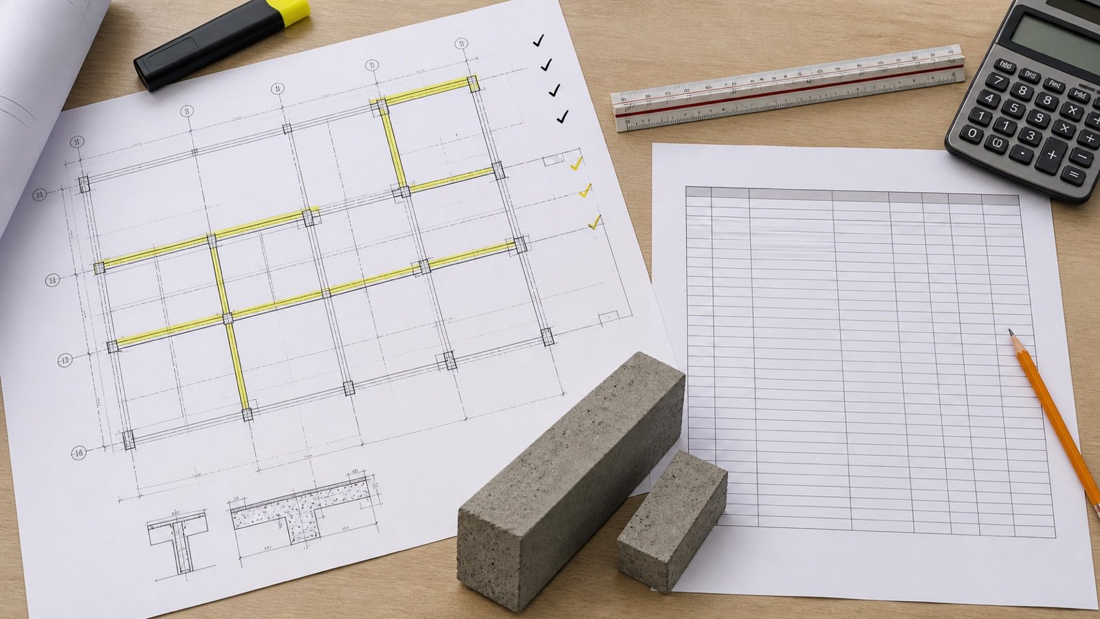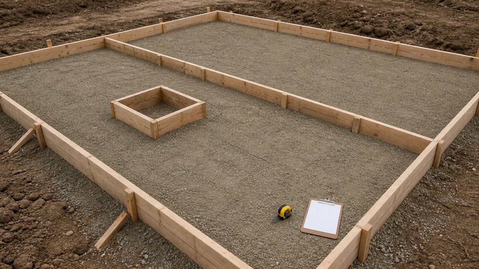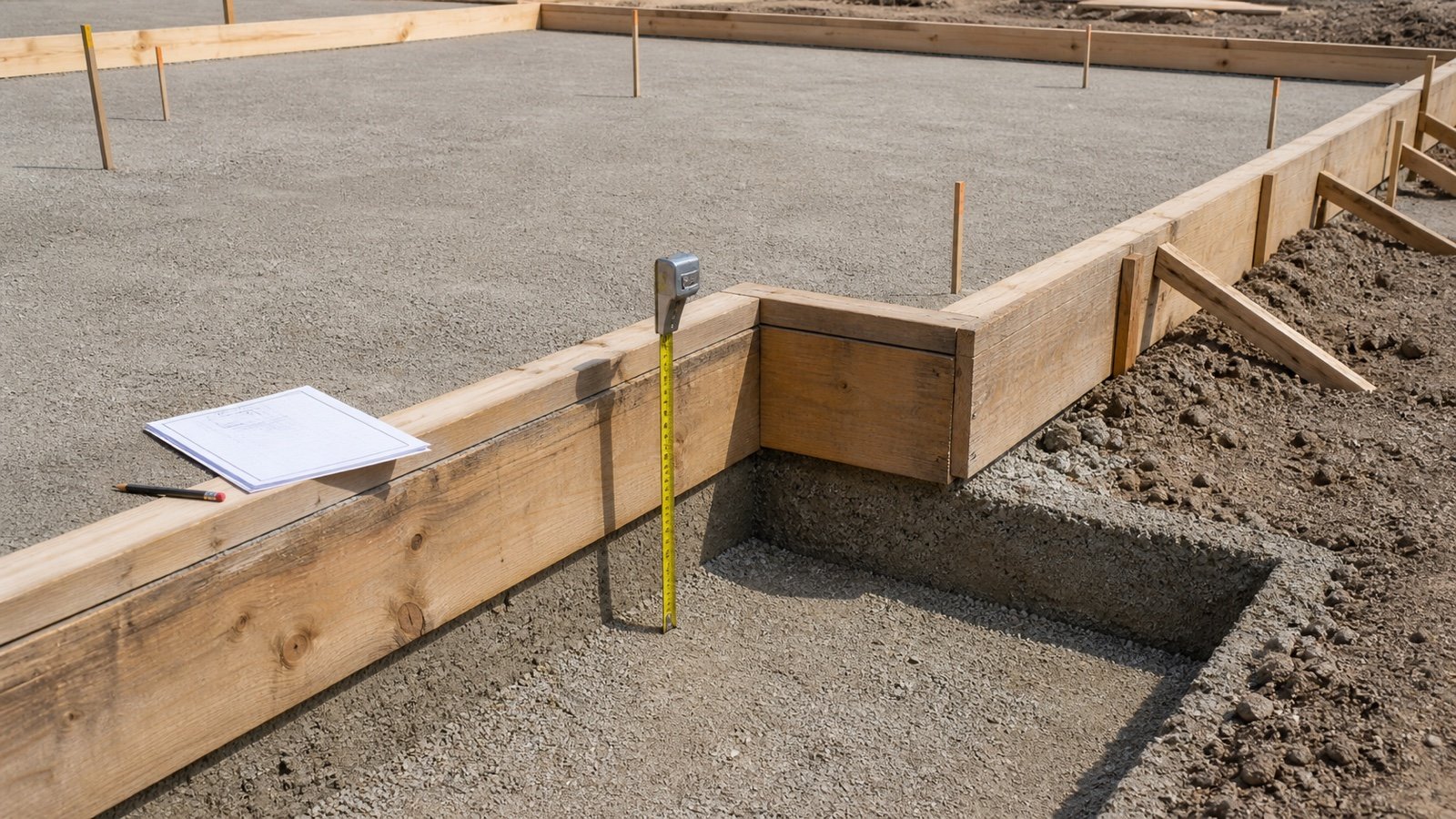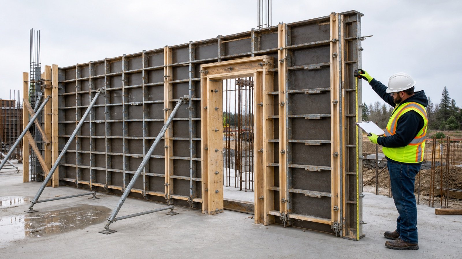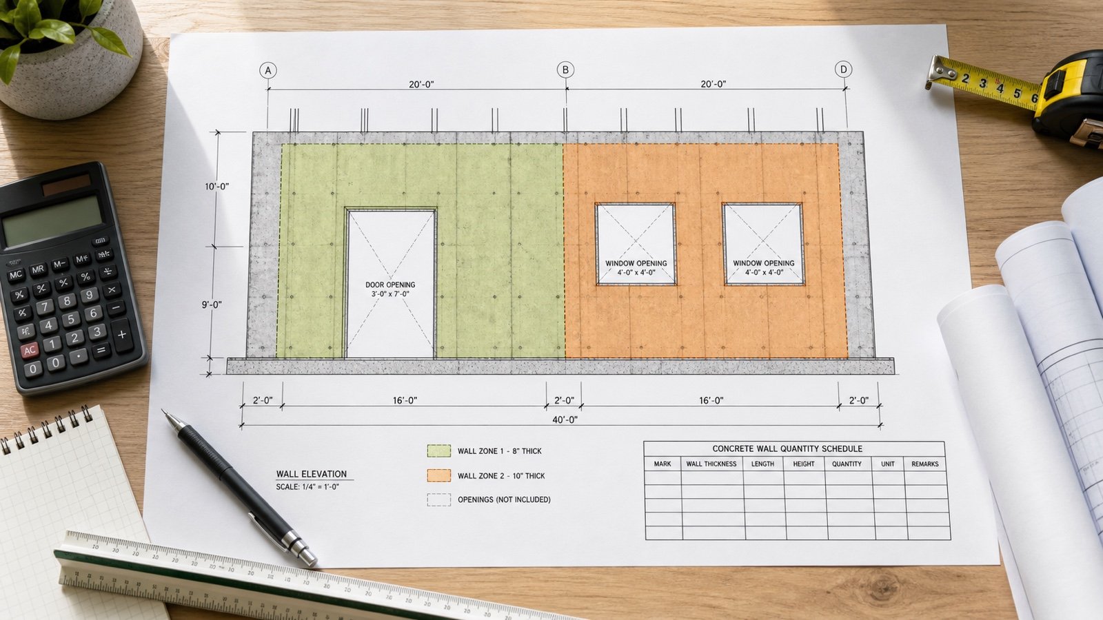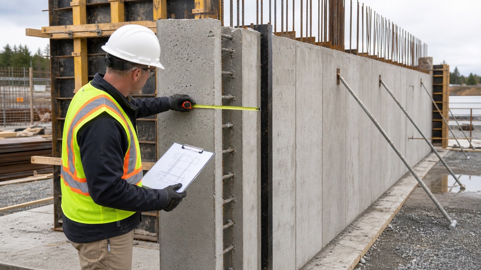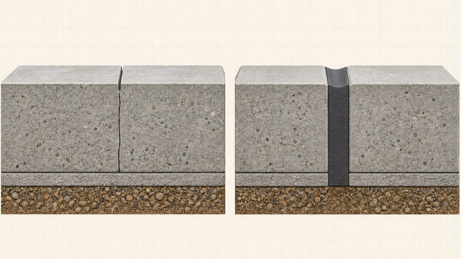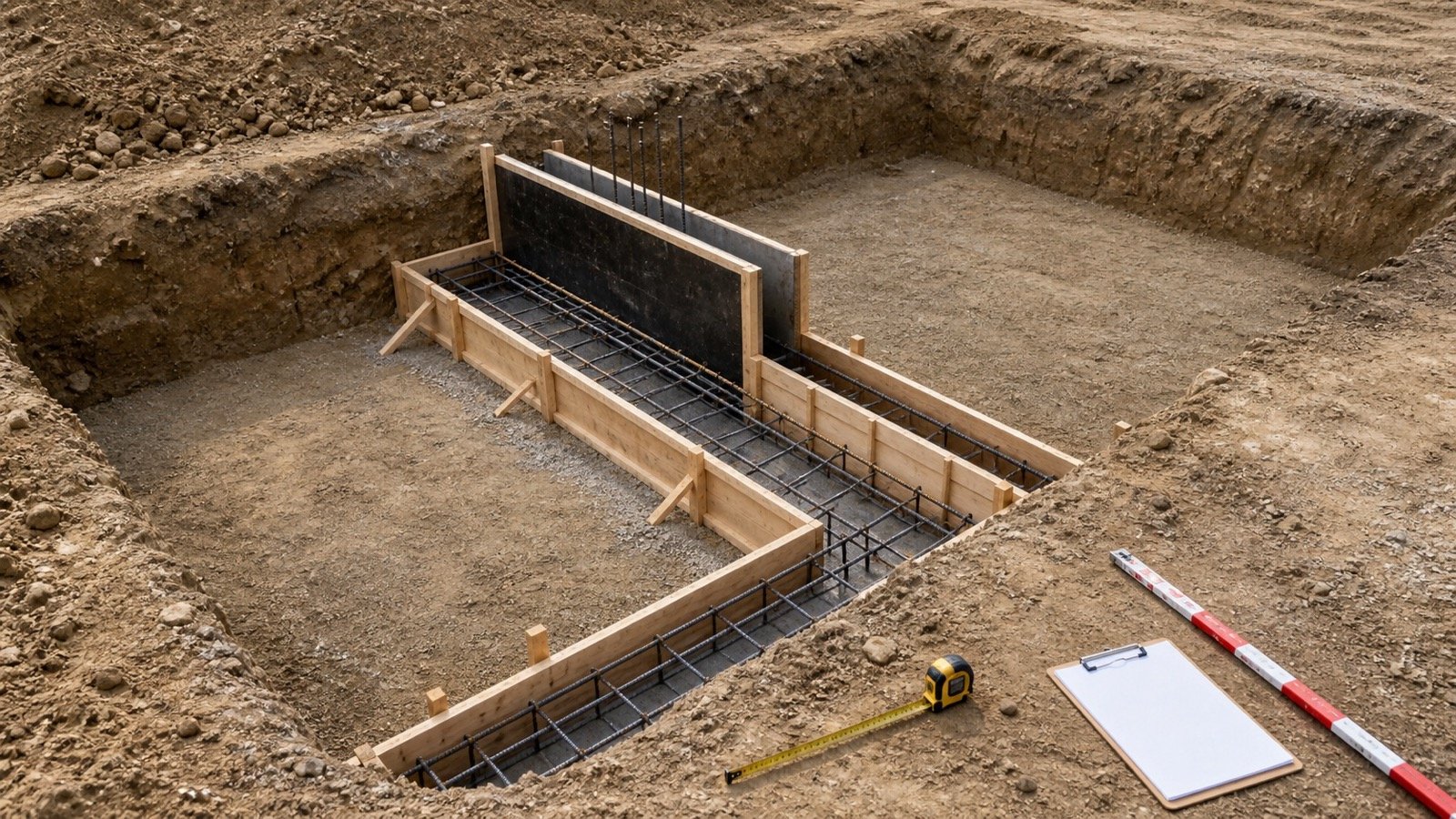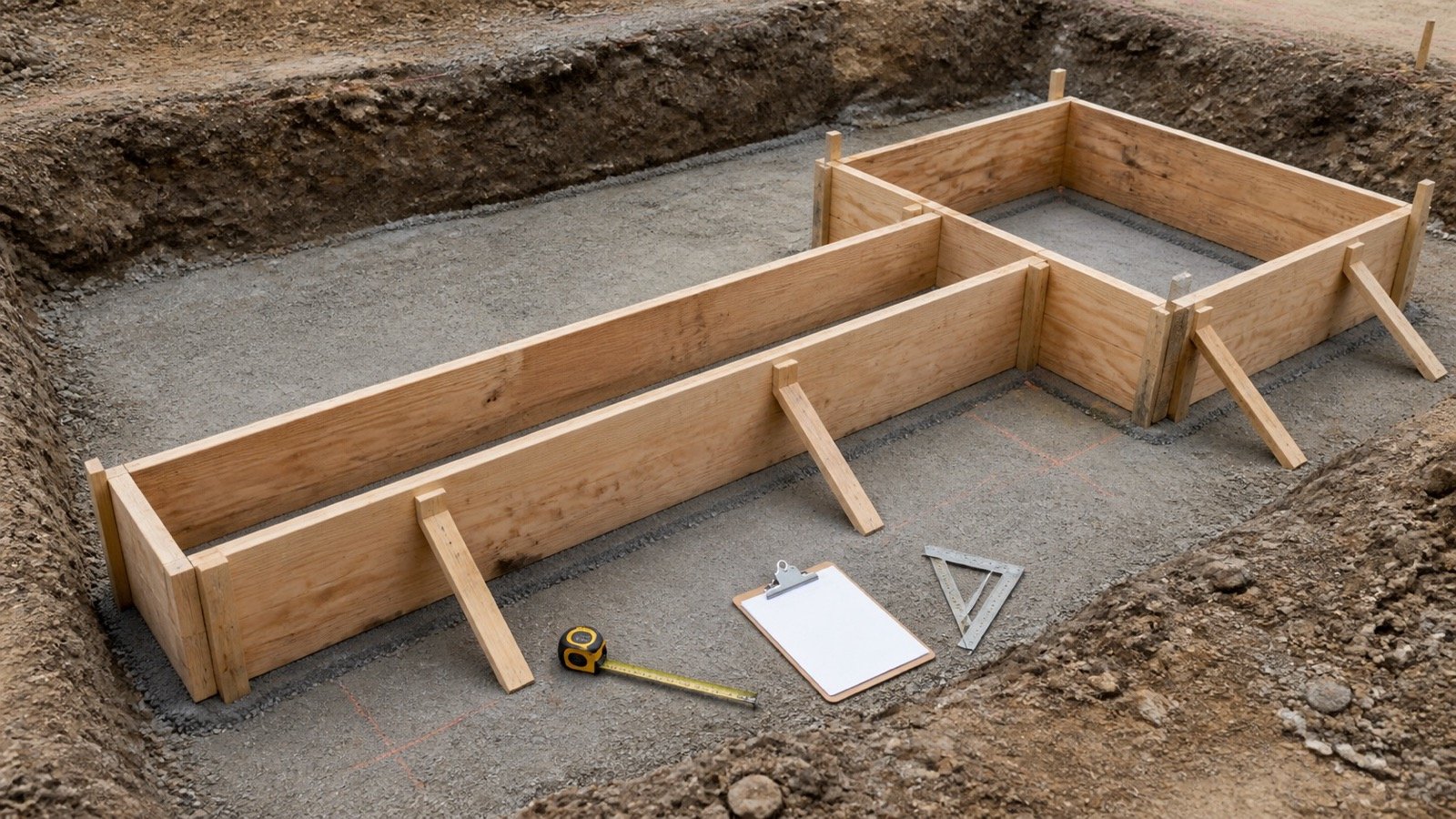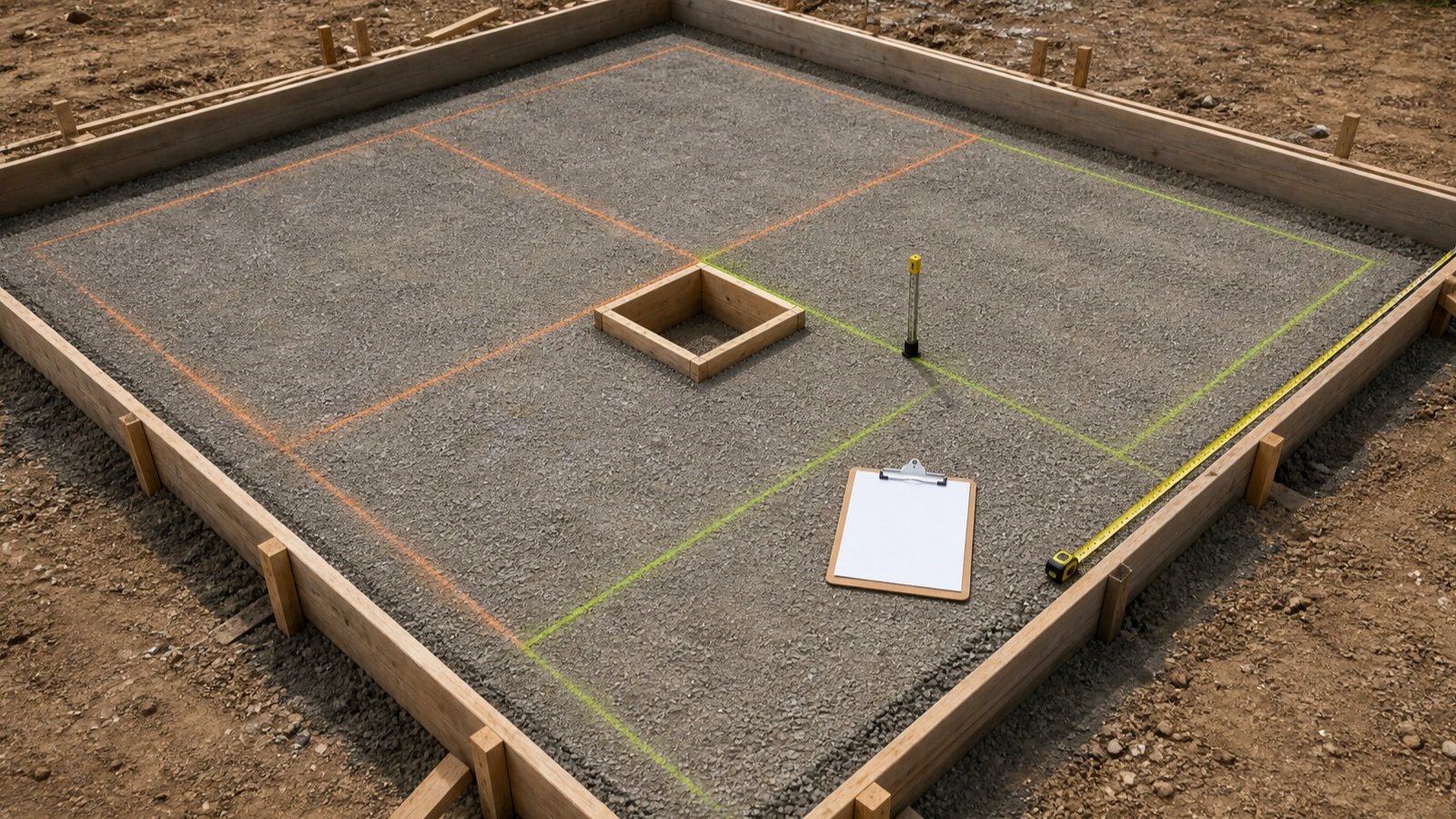
A slab rebar takeoff begins with the current structural and placing information. Mark the grid limits, bar directions, layers, openings and detail changes before counting a single line.
This workflow measures an approved layout. It does not choose bar size, spacing, cover, laps or reinforcement for a slab.
How do you measure rebar for a concrete slab?
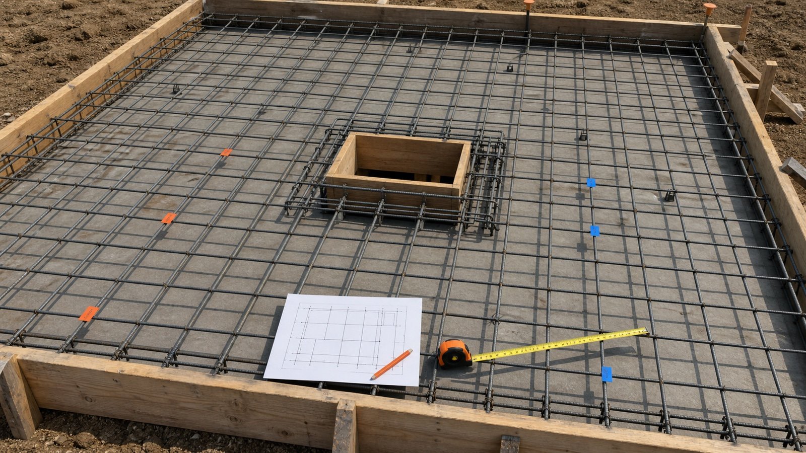
Split the slab into areas where one bar mark, direction, layer and spacing rule stays unchanged. For each area, count bars across the direction in which they are spaced, measure the length each bar runs, then add approved laps, bends and extra bars as separate lines.
CRSI explains that placing drawings show where the bars go in relation to the overall dimensions. ACI detailing guidance separates structural design information from the fabrication and placement information needed to assemble the reinforcement. Your takeoff should preserve those references.
Mark every takeoff zone and unresolved detail first. Use the Rebar Calculator only for a rectangular, uniformly spaced, single mat after its inputs are confirmed.
Which documents belong in the takeoff record?
Use one current document set and write its revision beside the quantity. General notes can define reinforcement rules that do not appear beside every slab callout.
| Document | Information to capture | Conflict check |
|---|---|---|
| Structural plan | Slab limits, grid lines, bar callouts, directions and zones | Revision, scale and written dimensions |
| Sections and details | Top or bottom face, layers, cover, edge bars, openings and supports | Every plan reference reaches the intended detail |
| General notes and specifications | Material, grade, coating, placing rules and submittal requirements | Project-specific note versus general standard |
| Placing drawings and bar list | Bar marks, shapes, cut lengths, quantities, laps and fabrication data | Approval status and latest revision |
| Clarifications and changes | Revised openings, pour limits, couplers and field changes | Change is approved and tied to affected marks |
How should a slab be divided into takeoff zones?
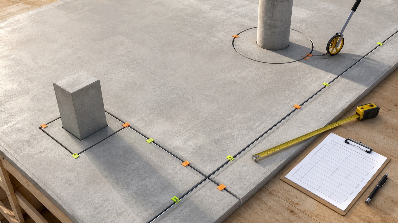
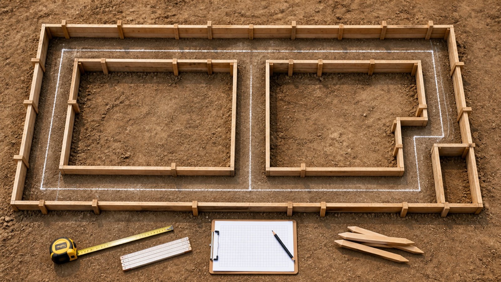
Create a new zone whenever bar size, spacing, direction, face, extent or detail changes. A large rectangle can contain several reinforcement layouts even when the concrete volume uses one outline.
- Trace the concrete boundary and construction joints.
- Mark the limits of each reinforcement callout.
- Separate top, bottom and added layers.
- Outline column strips, edge bands, thickened areas and local additions.
- Mark openings, blockouts, sleeves and penetrations.
- Assign a zone ID and list every bar mark inside it.
- Flag missing extents or conflicting notes for clarification.
Keep a baseline grid and local additions on separate quantity lines. This makes a later revision easier to audit and prevents an added band from disappearing inside one total.
What information should be read from each bar callout?
A bar callout needs a designation, spacing or quantity, direction, face or layer, extent and detail reference. Record any prefix, suffix, shape code or bar mark exactly as the project defines it.
| Field | Example entry | Why it matters |
|---|---|---|
| Zone and location | S1, grids A-C / 1-4 | Connects the quantity to a marked area |
| Bar mark | B12 | Connects plan, schedule and fabrication record |
| Designation | #5 or #16 | Selects the correct material and unit mass record |
| Direction | Runs east-west | Shows which perpendicular span controls the count |
| Face or layer | Bottom, outer layer | Prevents top and bottom quantities from being merged |
| Spacing basis | 200 mm maximum, centre to centre | Defines how gaps are counted |
| Extent and end detail | Grid A to C; Detail 5/S-402 | Controls length, termination and anchorage |
| Source | S-201 Rev 4 | Makes revision checks possible |
Is concrete cover the same as a bar-centerline offset?
Concrete cover is measured from the concrete surface to the outermost surface of the reinforcement. A plan centerline offset reaches the center of the bar, so the 2 measurements are different.
For one straight outer bar, a geometric conversion may add half the applicable bar diameter to the clear cover. Coatings, deformations, crossed layers, tolerances and project detailing can change the placing dimension that should be used. Read the approved detail or placing dimension instead of assuming a universal offset.
The Rebar Size and Weight Chart lists nominal U.S. bar diameters and explains why the outside deformation envelope can be larger. It remains a property reference, not a cover-design table.
Which dimension controls the number of bars?
Count across the spacing direction, which is perpendicular to the direction the bars run. Bars running along the slab length are counted across the slab width. Bars running along the width are counted across the length.
For a uniform grid with a maximum spacing and equal entered centerline offsets:
Clear length = slab length - 2 x centerline offset
Clear width = slab width - 2 x centerline offset
Long-running bars = ceiling(clear width / maximum spacing) + 1
Width-running bars = ceiling(clear length / maximum spacing) + 1
Rounding the gap count upward keeps an evenly distributed result at or below the entered maximum. A drawing with fixed bar lines, unequal end spaces, alternating spacing or explicit marks governs instead of this uniform method.
Worked example: metric slab rebar grid
An approved single-mat layout covers a 7.2 m x 5.4 m rectangular slab. The entered bar-centerline offset is 75 mm on each edge, and the maximum spacing is 200 mm in both directions.
- Clear length: 7.2 - 2 x 0.075 = 7.05 m.
- Clear width: 5.4 - 2 x 0.075 = 5.25 m.
- Long-running bars: ceiling(5.25 / 0.2) + 1 = 28 bars.
- Their actual equal spacing is 5.25 / 27 = 0.194444 m, or 194.444 mm.
- Width-running bars: ceiling(7.05 / 0.2) + 1 = 37 bars.
- Their actual equal spacing is 7.05 / 36 = 0.195833 m, or 195.833 mm.
- Installed grid length: 28 x 7.05 + 37 x 5.25 = 391.65 m.
- Grid intersections: 28 x 37 = 1,036.
The 391.65 m is straight installed grid length before any approved laps, hooks, anchorage, local additions, fabrication allowance or stock rounding.
Worked example: imperial slab rebar grid
A 24 ft x 16 ft slab has approved outer bar centerlines 3 in from each edge and a 12 in maximum spacing in both directions.
- Clear dimensions are 23.5 ft x 15.5 ft.
- Seventeen bars run 23.5 ft. Their spacing across 16 gaps is 11.625 in.
- Twenty-five bars run 15.5 ft. Their spacing across 24 gaps is 11.75 in.
- Installed grid length is 17 x 23.5 + 25 x 15.5 = 787 ft.
- The grid has 17 x 25 = 425 intersections.
Use the exact unit system stated by the project. NIST defines 1 ft as 0.3048 m and 1 in as 25.4 mm exactly, but converting a takeoff does not change the governing drawing convention.
How are openings measured without losing affected bars?
Resolve every affected bar line. An opening may stop some bars, leave others continuous and require trimmer or diagonal bars under an approved detail. Subtracting opening area cannot show those outcomes.
Suppose an approved detail shortens 3 baseline bars by 1.2 m each and adds 4 trimmer bars at 1.5 m:
Net length change = -(3 x 1.2 m) + (4 x 1.5 m) = +2.4 m
This arithmetic does not design the opening reinforcement. List the shortened bars and added marks separately so a reviewer can match them to the detail.
| Line | Quantity change | Length each | Length change |
|---|---|---|---|
| Affected baseline bars | 3 shortened | -1.2 m | -3.6 m |
| Approved trimmer bars | 4 added | 1.5 m | +6.0 m |
| Net check | Separate marks retained | Not applicable | +2.4 m |
How should top and bottom mats be counted?
Measure each mat and each layer as its own takeoff group. Top and bottom reinforcement can use different bar sizes, spacing, extents, lap zones and added bars.
Doubling one grid is valid only when the approved documents show 2 identical mats with the same limits and bar arrangement. Keep the 2 records separate even then, because supports, placing sequence and later revisions can differ.
Where do laps, stock lengths and cut lengths enter?
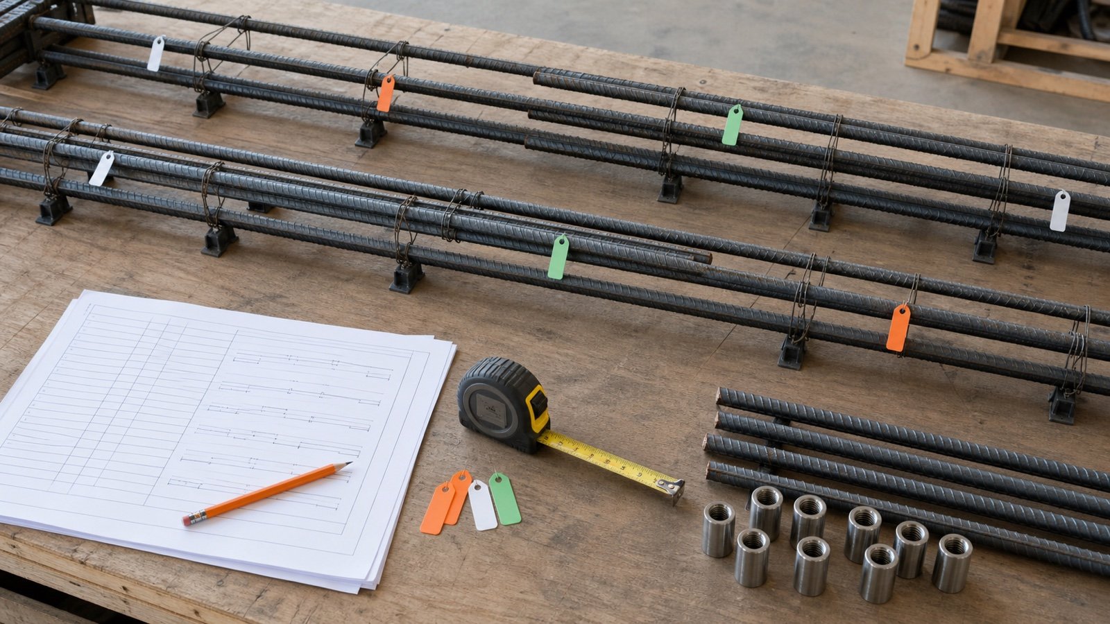
Add laps only from approved project information. CRSI notes that lap length depends on concrete strength and type, bar grade and size, spacing, cover and confinement. The engineer provides the location and lap information through the structural and placing documents.
Keep 3 quantity states visible:
| State | Includes | Use |
|---|---|---|
| Installed grid length | Geometric bar runs in the finished grid | Checks the layout |
| Cut length | Installed length plus approved laps, hooks, bends and mark geometry | Fabrication record |
| Order quantity | Approved cut plan, supplier stock, offcut reuse and stated allowance | Procurement |
Dividing total installed length by stock length gives a pooled length bound. It is not an exact purchase count when cuts do not nest or splice locations are restricted.
What should the finished takeoff worksheet contain?
A reviewer should be able to rebuild every quantity from the marked documents and the worksheet.
- project, slab, pour, zone, date, preparer and drawing revision;
- bar mark, designation, grade, coating and applicable specification;
- direction, face, layer, extent, spacing and centerline offsets;
- bar count, length each and installed length;
- opening deductions and added reinforcement as separate lines;
- approved lap, hook, bend, coupler and splice information;
- cut length, stock length, cut-plan reference, allowance and order quantity;
- unit-mass source, calculated mass and supplier quote basis;
- unresolved conflicts, clarifications and field changes.
Which takeoff shortcuts cause errors?
- Counting bars along the direction they run instead of across their spacing span.
- Using floor division when spacing is an entered maximum.
- Calling clear cover a centerline offset.
- Subtracting an opening by area without checking individual bar lines.
- Combining top, bottom and added bars into one untraceable quantity.
- Estimating reinforcement from concrete volume when the project provides bar layouts.
- Applying one lap multiple to every bar and location.
- Treating pooled stock length as a finished cut plan.
- Using an old drawing revision or missing a general-note requirement.
- Rounding every line before the group total.
What design and safety limits still apply?
This workflow cannot design reinforcement, approve a substitution, resolve a drawing conflict or set cover, spacing, development, anchorage, splices, supports or tolerances. Structural drawings, calculations, specifications, approved placing information and responsible professionals control those decisions.
Rebar installation also needs a site safety plan for lifting, cutting, access, stability and exposed ends. OSHA 29 CFR 1926.701(b) requires guarding protruding reinforcing steel where a fall could cause impalement in covered U.S. construction work. Follow every applicable project and local requirement.
After the worksheet is checked, use the Rebar Calculator for a qualifying uniform grid and the Concrete Planning hub for related concrete-volume and reinforcement resources.
Sources and source scope
- CRSI Placing Bars: the relationship between placing drawings, overall dimensions, bar supports and required cover.
- CRSI Splicing Bars and Lap Splices: variables that affect lap length and the role of structural and placing information.
- ACI Detailing in Concrete and ACI PRC-315-18 preview: detailing, fabrication, placing information and cover terminology.
- NIST Guide to the SI, Appendix B: exact international-foot and inch conversions.
- OSHA 29 CFR 1926.701: United States protruding-rebar impalement protection context.
Source scope: CRSI and ACI support placing, detailing and splice context. NIST supports unit conversion. OSHA supports the named U.S. workplace rule. Project drawings, specifications, approved submittals, bar lists, supplier records and responsible professionals govern the actual reinforcement.
Review note: Saleem Sial owns the research and editorial record. Source checks, independent calculation fixtures, editorial review, build validation, link crawl, schema review and rendered QA form the internal publication gate. Waseem Sial, External Reviewer and Engineer, is listed for ongoing external review; no completed review date is claimed.