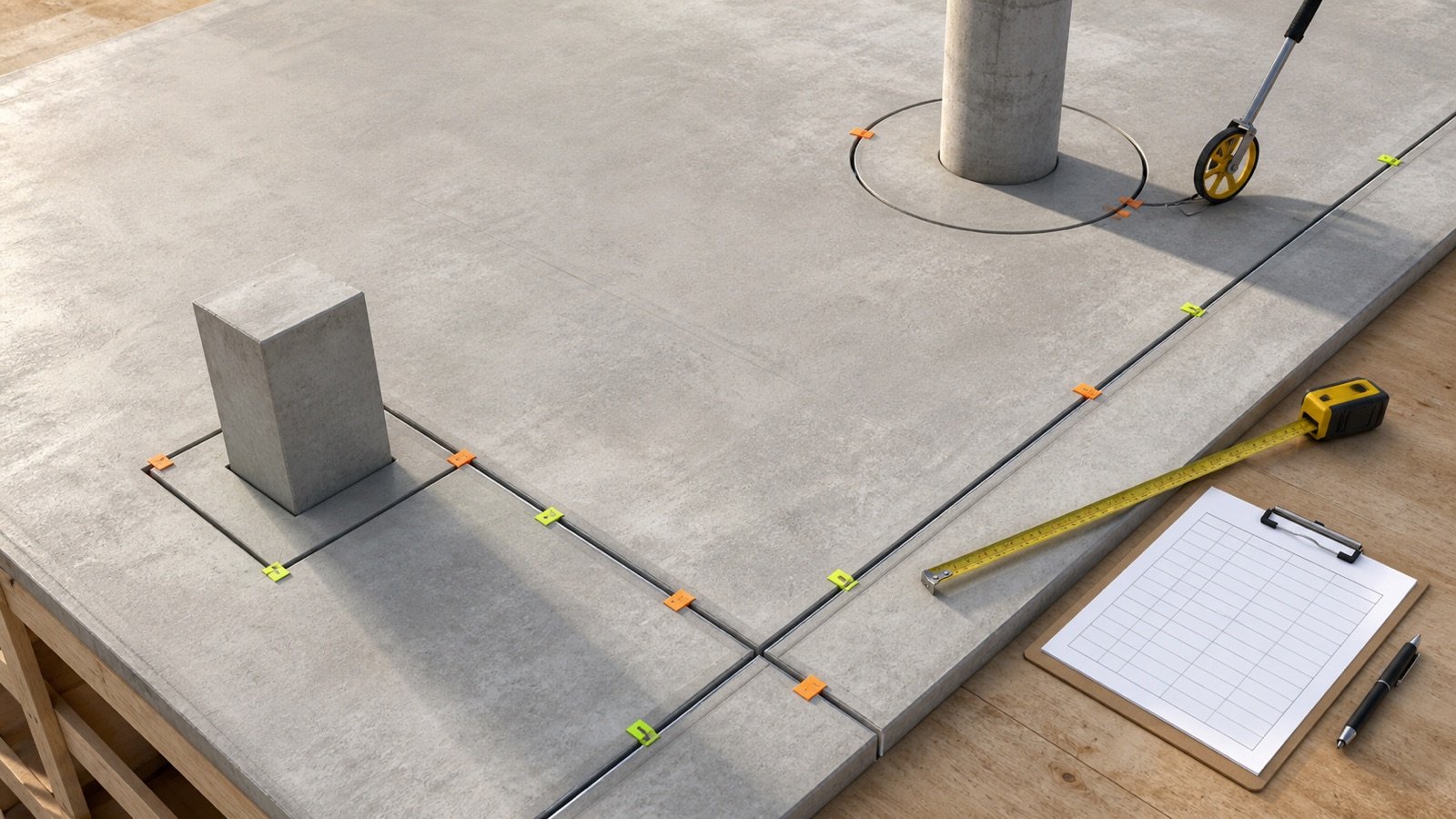
Expansion-joint material takeoff starts with the approved joint path. Use the expansion-joint measurement guide to trace straight runs, curves, shared boundaries, transitions and changing profiles before entering the total.
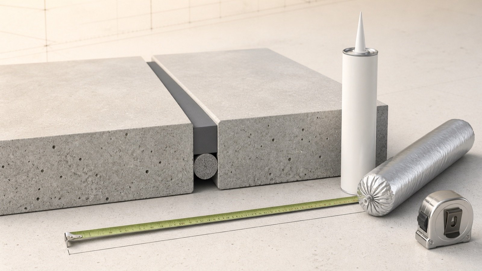
This calculator keeps joint length, sealant volume, packages, filler length, and rolls separate. It uses project-entered dimensions and does not generate a structural joint layout. Check the control joint vs expansion joint guide when the joint type is unclear, use the concrete expansion joint materials guide to separate filler, backing and sealant inputs, and check sealant coverage per tube before converting volume into packages.
How much sealant and filler does your approved joint plan need?
Select the rectangular slab edges that receive isolation material and add any other material-treated joint length from the drawings or field measure. The calculator multiplies total length by the installed sealant width and depth, applies your allowance, and rounds entered package and roll sizes upward.
Use the product data sheet and project details for joint width, sealant depth, filler size, backing, primers, and installation limits. A slab dimension alone cannot establish those values.
What does the expansion joint calculator include?
The calculator totals straight slab-edge joints and an additional entered length. It then calculates a rectangular sealant reservoir and optional whole product units.
| Result | Calculation | Use |
|---|---|---|
| Selected slab-edge length | Selected length-parallel sides × slab length, plus selected width-parallel sides × slab width | Isolation material along chosen rectangular edges |
| Total joint length | Selected edge length + additional approved joint length | Material-treated length used by later calculations |
| Raw sealant volume | Total length × installed joint width × installed sealant depth | Geometric rectangular volume before allowance |
| Planned sealant volume | Raw volume × entered allowance factor | Quantity used for package rounding |
| Whole packages | Planned volume ÷ entered package volume, rounded up | Whole-unit planning count |
| Whole filler rolls | Allowance-adjusted filler length ÷ entered roll length, rounded up | Length-based roll count for the matching filler size |
The tool assumes a constant rectangular sealant cross-section. Manufacturer coverage may differ when the installed profile, packaging, joint shape, substrate, application loss, or product density changes.
Which concrete joint type are you measuring?
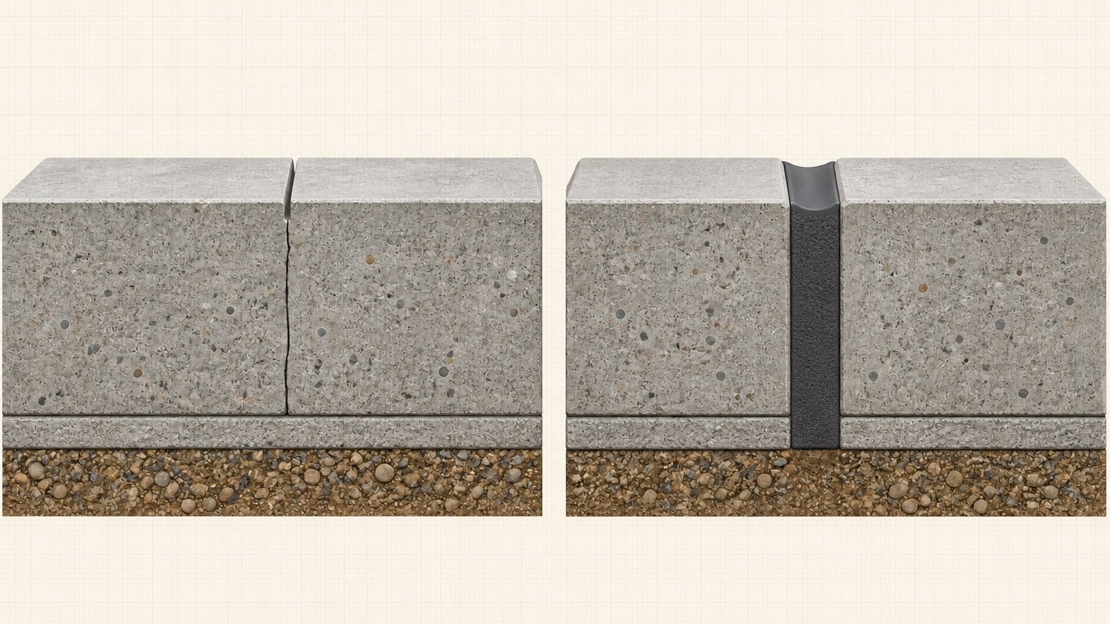
NRMCA CIP 6 separates slab joints by function. Contraction joints form planned weakened planes for shrinkage cracks. Isolation or expansion joints separate a slab from another part of the structure so the parts can move independently. Construction joints occur where successive concrete placements meet.
This page calculates material quantity for approved isolation or expansion joints. You can also use the rectangular sealant-volume formula for another joint type when its drawing and product instructions call for the same material profile. Record the joint type with the takeoff.
Do not use a contraction-joint spacing rule to place expansion joints. NRMCA's slab-thickness spacing guidance concerns contraction joints, while isolation joints occur at restraints such as walls, footings, columns, adjoining slabs, curbs, stairs, and similar obstructions.
How do you measure selected slab-edge joints?
Enter the slab's plan length and width. Choose 0, 1, or 2 isolated sides parallel to each dimension.
A 6 m × 4 m slab with both 6 m sides and one 4 m side isolated has 16 m of selected edge length:
Selected edge length = 2 × 6 m + 1 × 4 m = 16 m
Select only edges that receive the same material system represented by the sealant and filler inputs. A free slab edge, bonded construction joint, saw-cut contraction joint, doweled movement joint, or edge with another detail may need a separate line item.
Where does additional approved joint length come from?
Use the additional-length field for interior movement joints, joints around columns or penetrations, curved runs, separate slab regions, and other material-treated segments listed on the joint plan.
Measure curves along their centerline. For a circular isolation joint, use the approved joint centerline diameter and calculate circumference as π × diameter. Add separate segments once; shared boundaries can otherwise appear twice when you total slab regions.
Split the takeoff when width, sealant depth, filler height, product, or allowance changes. One total length cannot preserve different cross-sections.
Which formulas calculate sealant and filler quantity?
The calculator uses a rectangular sealant cross-section. Metric mode converts the joint length to millimetres before calculating cubic millimetres; 1 mL equals 1,000 mm³.
Total joint length = selected slab-edge length + additional approved length
Raw sealant volume = total joint length × installed joint width × installed sealant depth
Planned sealant volume = raw volume × (1 + allowance % ÷ 100)
Whole packages = ceiling(planned sealant volume ÷ entered package volume)
Whole filler rolls = ceiling(total joint length × allowance factor ÷ entered roll length)
US customary mode uses the 2026 NIST relationship of 1 US fluid ounce = 1.8046875 in³. The result also shows US gallons at 128 US fluid ounces per gallon.
Worked metric expansion-joint example
A 6 m × 4 m slab has both 6 m sides and one 4 m side isolated. The drawing also lists a 4 m interior material-treated joint. Installed sealant dimensions are 12 mm wide × 6 mm deep.
- Selected slab-edge length: 2 × 6 + 1 × 4 = 16 m.
- Total joint length: 16 + 4 = 20 m.
- Raw sealant volume: 20,000 mm × 12 mm × 6 mm = 1,440,000 mm³.
- Raw liquid volume: 1,440,000 ÷ 1,000 = 1,440 mL, or 1.44 L.
- With a 10% allowance: 1,440 × 1.10 = 1,584 mL.
- For an entered 600 mL package: ceiling(1,584 ÷ 600) = 3 packages.
- Allowance-adjusted filler length: 20 × 1.10 = 22 m.
- For an entered 15.25 m roll: ceiling(22 ÷ 15.25) = 2 rolls.
The package and roll sizes are example inputs. Confirm the actual package yield, filler width, thickness, compatible sealant system, and installation details before ordering.
Worked imperial expansion-joint example
A 20 ft × 12 ft slab has isolation material around all 4 sides and 10 ft of additional approved joint. The installed sealant profile is 0.5 in wide × 0.25 in deep.
- Selected perimeter: 2 × 20 + 2 × 12 = 64 ft.
- Total joint length: 64 + 10 = 74 ft.
- Raw volume: 74 × 12 × 0.5 × 0.25 = 111 in³.
- Raw liquid volume: 111 ÷ 1.8046875 = 61.506 US fl oz.
- With a 10% allowance: 61.506 × 1.10 = 67.657 US fl oz, or 0.529 US gal.
- For an entered 10.1 US fl oz package: ceiling(67.657 ÷ 10.1) = 7 packages.
- Allowance-adjusted filler length: 74 × 1.10 = 81.4 ft.
- For an entered 50 ft roll: ceiling(81.4 ÷ 50) = 2 rolls.
The result estimates liquid volume from the rectangular installed profile. Product instructions govern usable yield, nozzle loss, tooling, backing, curing, and suitability.
How should joint width and sealant depth be chosen?
Use the dimensions on the approved joint detail and the selected sealant's current product data. Joint movement, substrate, exposure, traffic, temperature, product movement capability, backing, bond line, and installation tolerance can change the required profile.
Sika USA's current Sikaflex NP 1 page publishes width-specific sealant-depth ranges. For example, its table does not use one depth for every joint width. That table supports the need for product-specific dimensions; it does not set a default for another sealant.
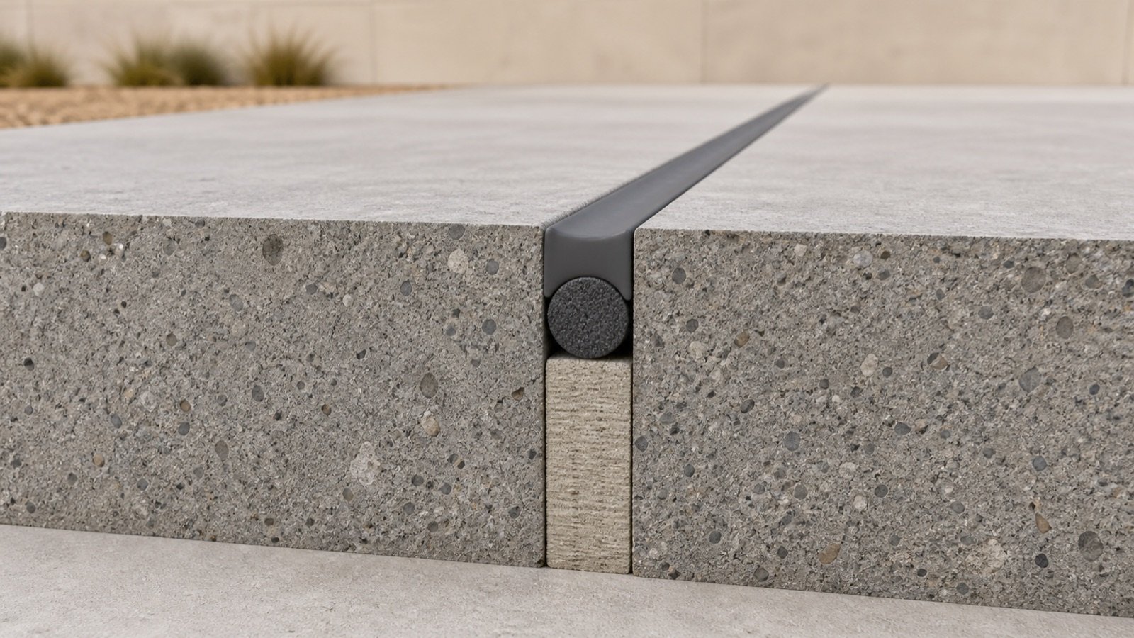
Measure sealant depth at the location defined by the manufacturer. Backer rod or a bond breaker often controls the sealant profile and helps prevent unwanted adhesion. The calculator does not size backer rod or test compatibility.
How does package rounding work?
Enter the usable liquid volume stated for one cartridge, sausage, pail, or other package. The calculator divides planned sealant volume by that entry and rounds upward to a whole package.
A package label may state nominal contents rather than guaranteed installed coverage. Material left in the nozzle, package, mixer, or pail reduces field yield. A manufacturer's coverage table can also account for a profile or application method that differs from the simple rectangular volume.
Keep the unrounded planned volume in the takeoff. Whole-package rounding can create a larger percentage difference on a short repair than on a long run.
What does the filler-roll result mean?
The roll result covers length only. Enter the roll length for filler that already matches the approved joint width, required filler height, compressibility, material standard, and exposure.
Sika Canada lists one current polyethylene filler product as a 15.25 m (50 ft) roll with a 10 cm (4 in) strip width. This product record shows why length and strip width belong in the purchasing check. It does not establish a universal roll size or prove suitability for another market or project.
Sheet filler, pre-cut strips, curved pieces, column wraps, intersections, butt joints, and damaged offcuts need a cutting plan. The calculator's whole-roll result assumes the entered roll can provide the allowance-adjusted length.
How should the allowance be applied?
The calculator applies one entered percentage to sealant volume and filler length. Keep it at 0% when you want the geometric quantity.
Use a documented project assumption when you add allowance. Joint intersections, cut ends, unusable offcuts, package residue, tooling loss, substrate variation, and repairs affect filler and sealant in different ways. Run separate takeoffs when those materials need different percentages.
Allowance does not cover a wider joint, deeper sealant profile, missing joint segment, or changed product. Revise the measured inputs when the design or field condition changes.
Can you use the calculator for an existing joint repair?
Yes, when you measure the cleaned joint and use the repair system's installed sealant width and depth. Enter the total repaired length in the additional-length field if the slab-edge selector does not fit the repair.
Existing joints can vary in width and depth. Divide the repair into measured sections when the profile changes. Remove failed material, prepare the substrate, choose backing and primer, and confirm adhesion under the manufacturer's instructions.
Sika's NP 1 instructions require sound, cured, dry, clean substrates free of listed contaminants. Another product can have different preparation, moisture, temperature, primer, or cure requirements.
Which joint conditions need a separate takeoff?
| Condition | Reason to split the quantity |
|---|---|
| Different joint widths or sealant depths | Sealant volume per unit length changes |
| Several sealant products or package sizes | Coverage, compatibility, and whole-package rounding change |
| Sheet filler and roll filler | Cutting and purchasing units differ |
| Curves, columns, and penetrations | Centerline length and offcut use need separate measurement |
| Doweled or load-transfer joints | Hardware, sleeves, alignment, and reinforcement need another material schedule |
| Traffic and non-traffic profiles | Installed depth, backing, and product selection may differ |
| Contraction-joint saw cuts | Saw-cut length and depth are a different task from full-depth isolation filler |
Common expansion-joint quantity mistakes
- Using a contraction-joint spacing rule as an expansion-joint layout.
- Selecting all 4 slab edges when only the drawing-listed restraints receive isolation material.
- Counting a shared joint from both adjoining slab regions.
- Measuring a curve by its straight chord instead of its joint centerline path.
- Using the full filler depth as the sealant depth.
- Entering nominal package contents without checking usable product coverage.
- Applying one cross-section to joints that change width or depth.
- Ordering filler by length without checking strip width, height, thickness, and product type.
- Adding allowance twice, once in measured length and again in the percentage field.
- Calling the output a joint design or a code-compliance check.
Which safety and construction checks remain?
Confirm the joint plan, substrate condition, filler and sealant compatibility, backer or bond-breaker detail, primer, installation temperature, moisture limit, cure time, traffic reopening, personal protective equipment, and waste handling before work.
Concrete cutting and grinding can create respirable crystalline silica. For United States construction workplaces, OSHA 29 CFR 1926.1153 includes specified exposure-control methods for handheld and walk-behind saw tasks. The employer's exposure-control process and the selected equipment instructions govern the work.
Joint timing, depth, load transfer, dowels, reinforcement interruption, waterproofing, fire rating, and structural separation sit outside this quantity calculation. Use the drawings, specifications, current product data, and responsible professionals.
What should the joint material record contain?
- Project, slab or pour mark, joint type, drawing revision, detail, date, and preparer.
- Selected slab edges, additional runs, curves, columns, intersections, and excluded segments.
- Measured length by joint width, sealant depth, product, and exposure condition.
- Raw sealant volume, allowance reason, planned volume, package size, and whole-package count.
- Filler material, strip width and height, roll or sheet size, allowance, and cutting plan.
- Backer rod or bond breaker, primer, substrate preparation, compatibility, and cure requirements.
- Unresolved design, safety, access, weather, traffic, and field-condition items.
Use the Ready-Mix Concrete Calculator for concrete order volume and the Rebar Calculator for an approved rectangular reinforcement grid. The concrete planning hub links the published concrete quantity tools and guides.
Sources and scope
- NRMCA CIP 6: Joints in Concrete Slabs on Grade: joint-type definitions, common isolation locations, and the need to plan joint locations.
- ACI PRC-224.3-95, reapproved 2013: published scope for joint terminology, movement, sealants, techniques, and structure-specific conditions.
- Tremco Sealant Calculator: rectangular expansion-joint sealant quantity from entered length, width, and depth.
- Sika USA Sikaflex NP 1: one product's width-specific sealant-depth table and substrate preparation.
- SikaCem Concrete Expansion Joint: one current filler product's roll length, strip width, and installation scope.
- NIST Handbook 133, 2026, Appendix E: US fluid-ounce, cubic-inch, millilitre, and US-gallon conversions.
- OSHA 29 CFR 1926.1153: US construction silica-control context for concrete saw tasks.
Source scope: NRMCA and ACI support joint terminology and design scope. Tremco supports rectangular sealant geometry. Sika pages show why installed depth, preparation, filler size, and yield depend on the selected product. NIST supports unit conversion. OSHA supports the named United States workplace rule. Project drawings, specifications, product data, field measurements, safety plans, and responsible professionals govern the work.
Review note: Saleem Sial owns the research and editorial record. Formula fixtures, source checks, build validation, and rendered QA form the internal publication gate. Waseem Sial, External Reviewer and Engineer, is listed for ongoing external review; no completed review date is claimed.