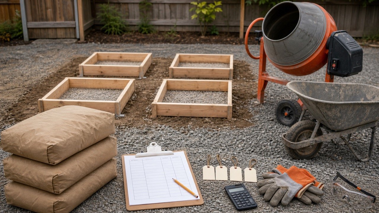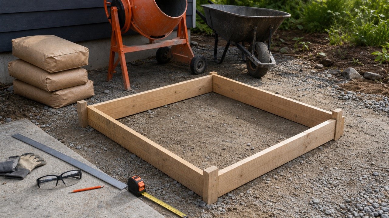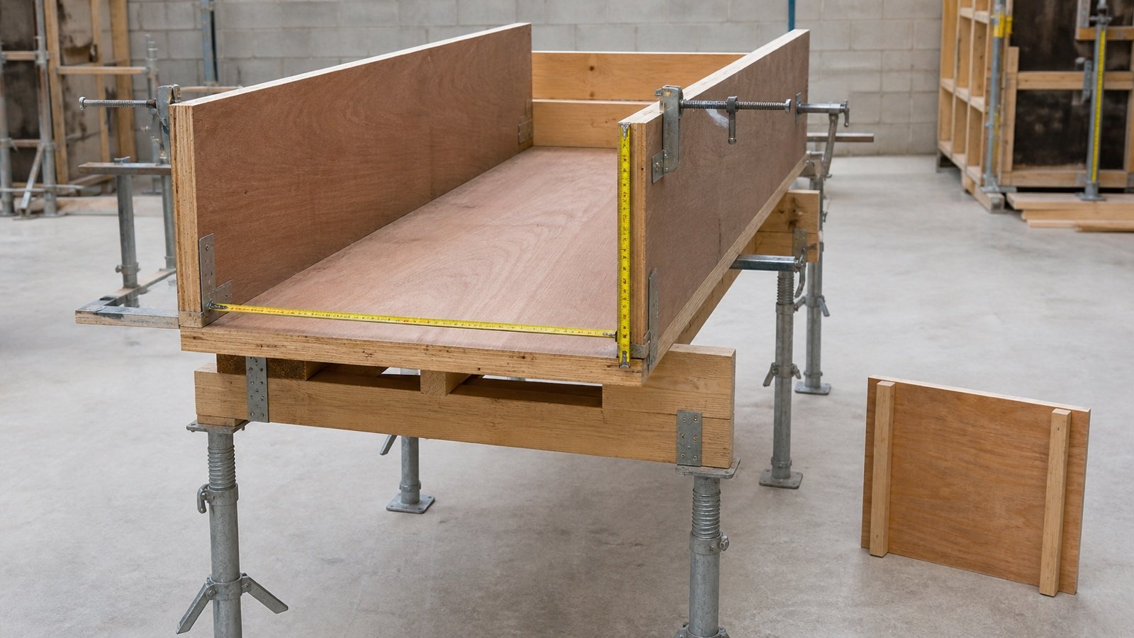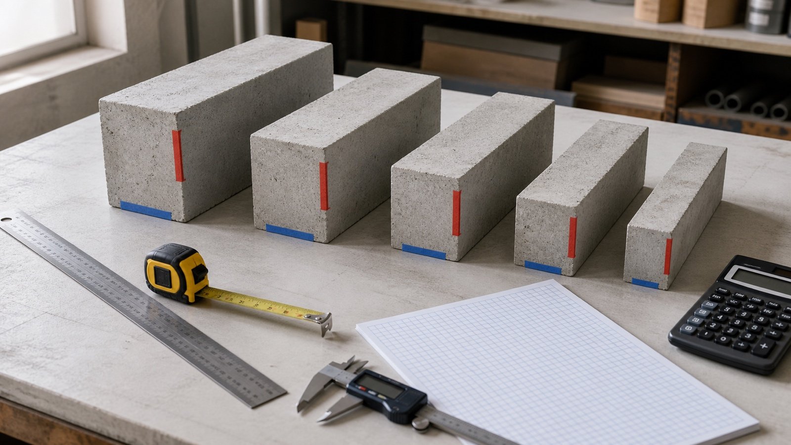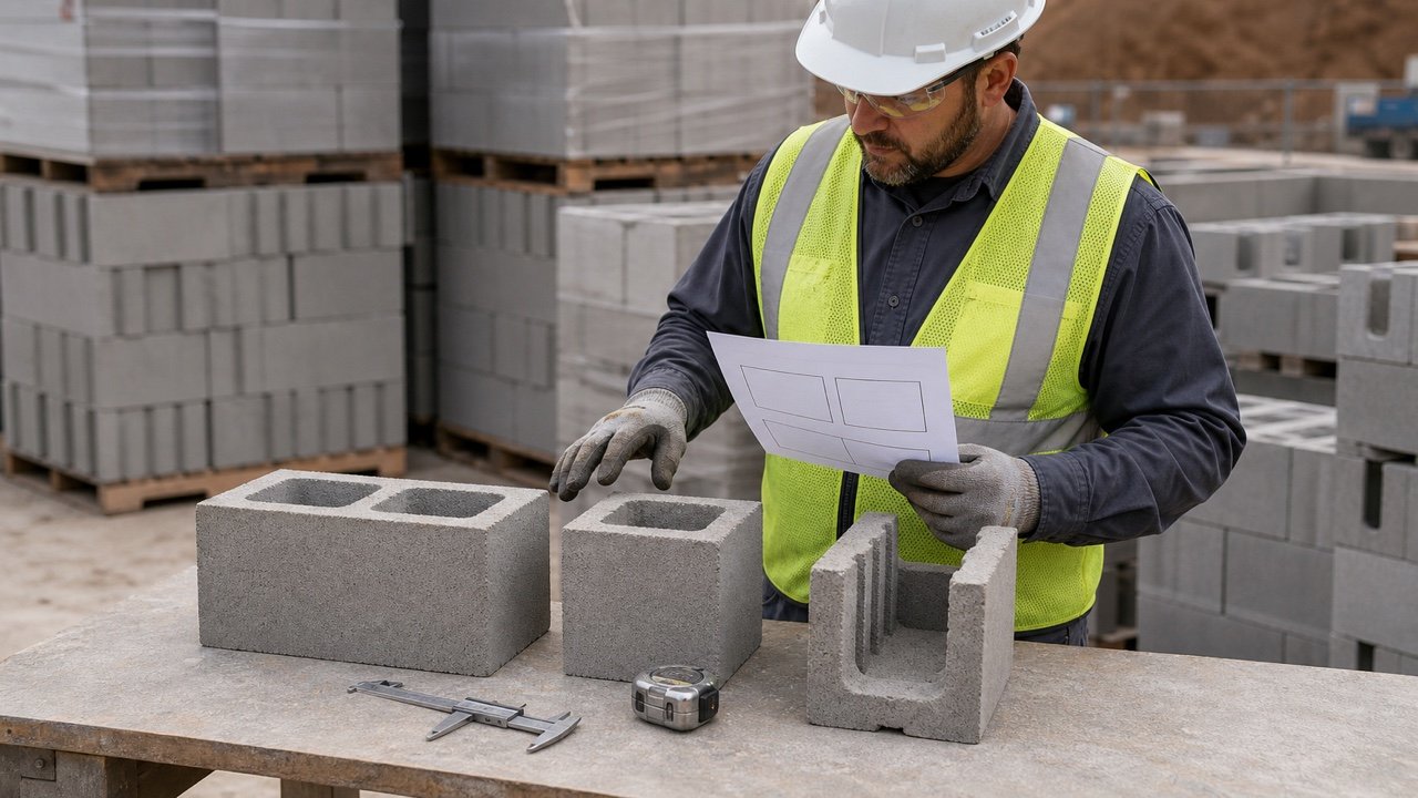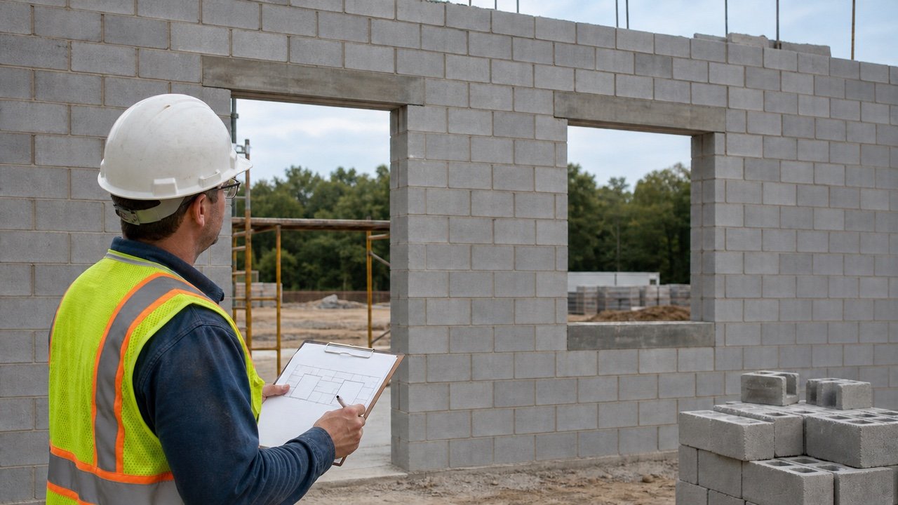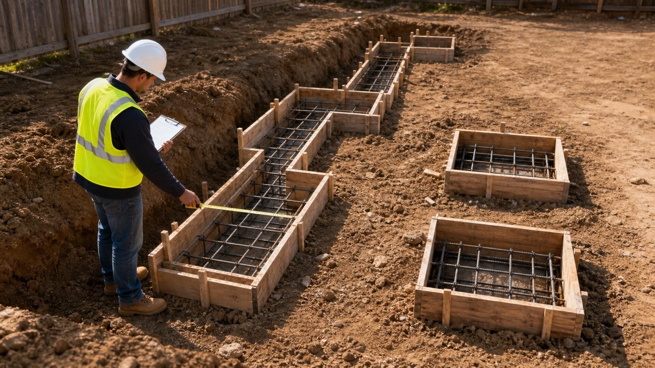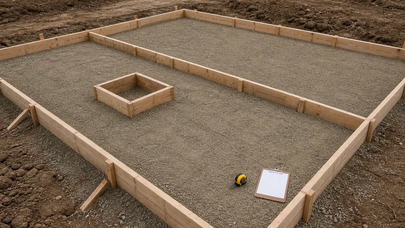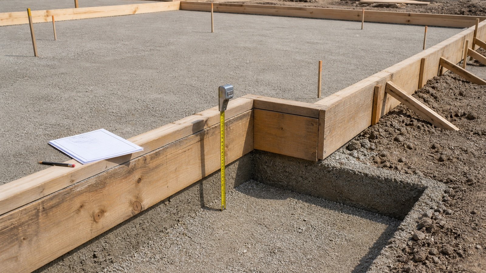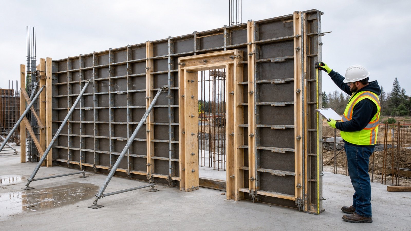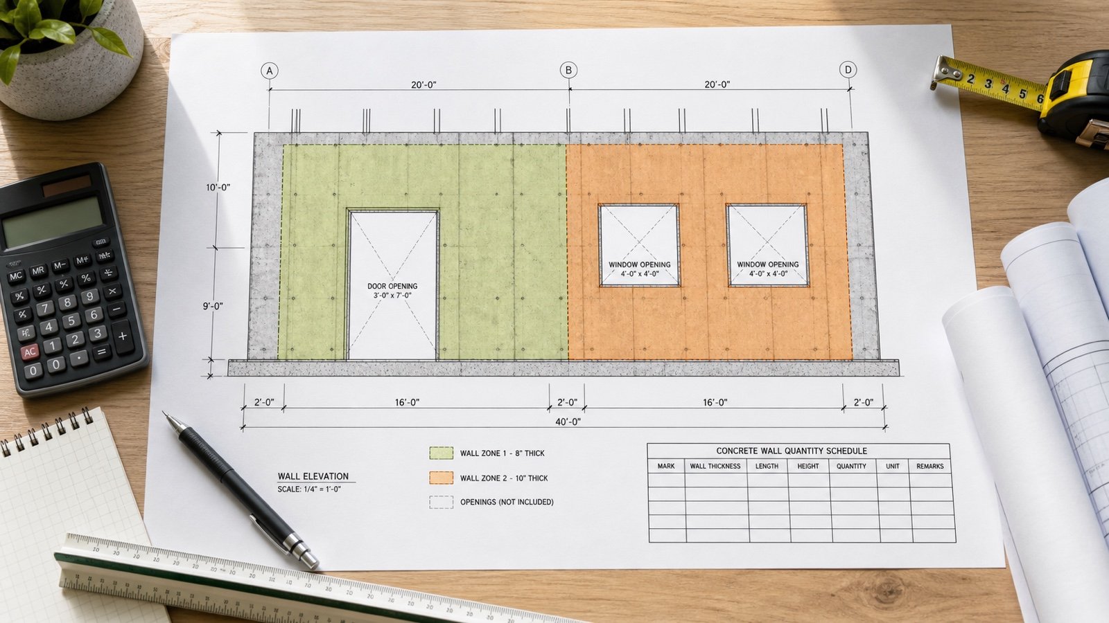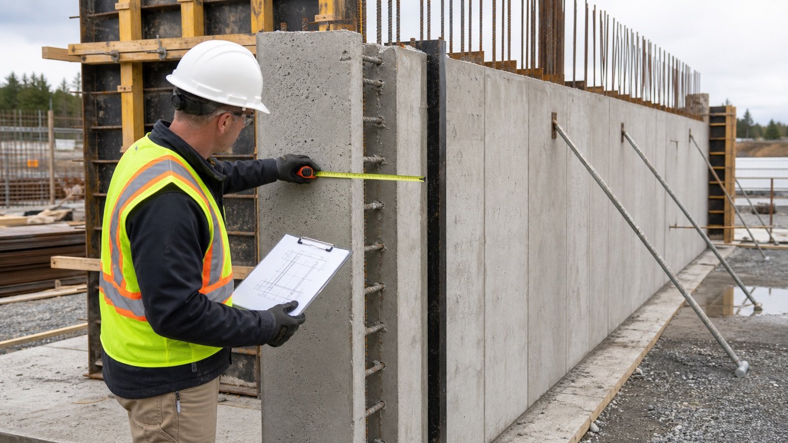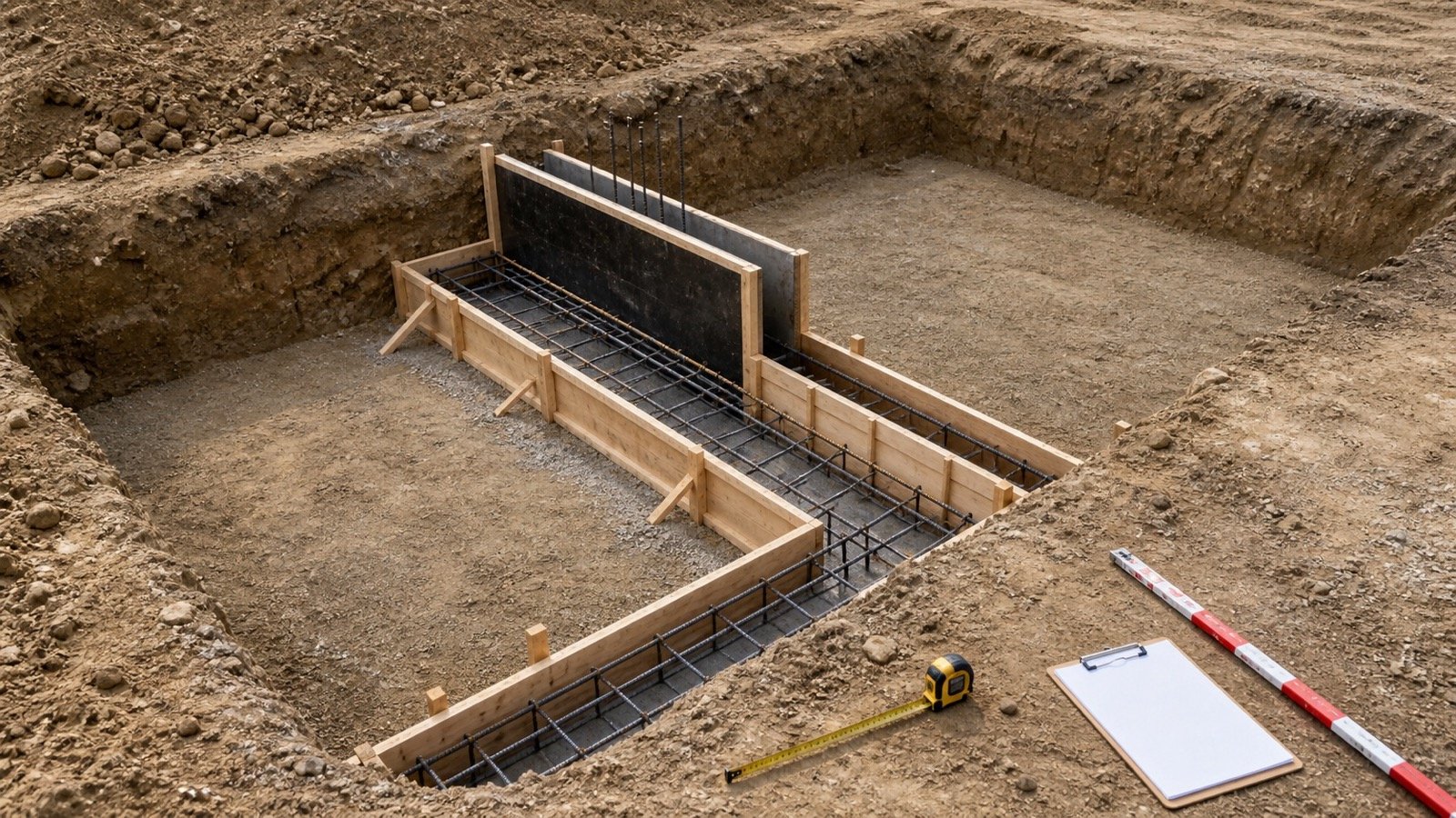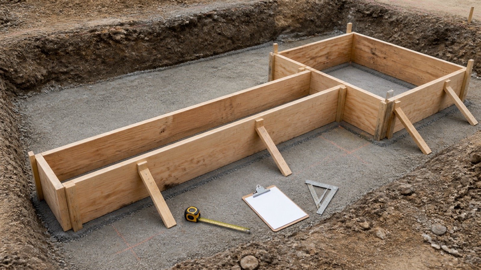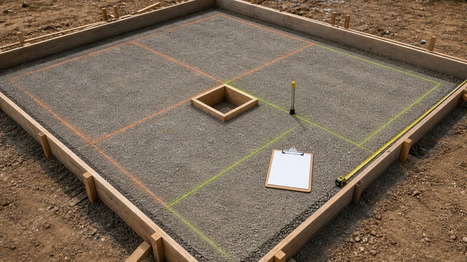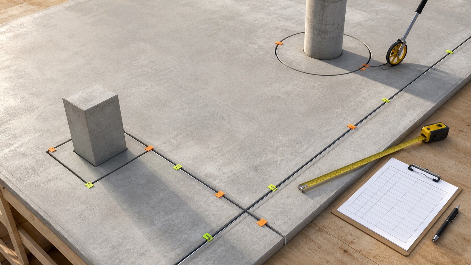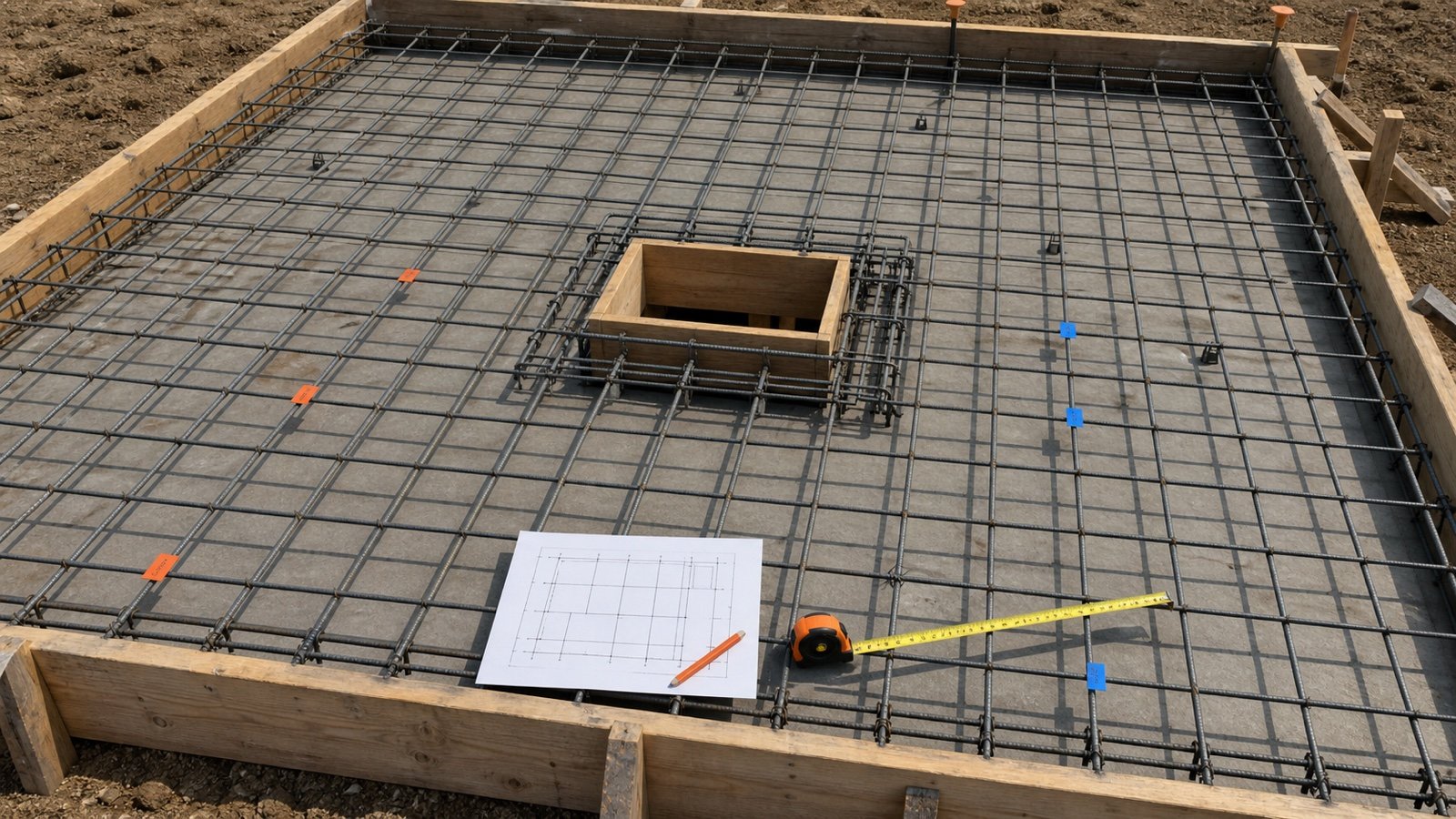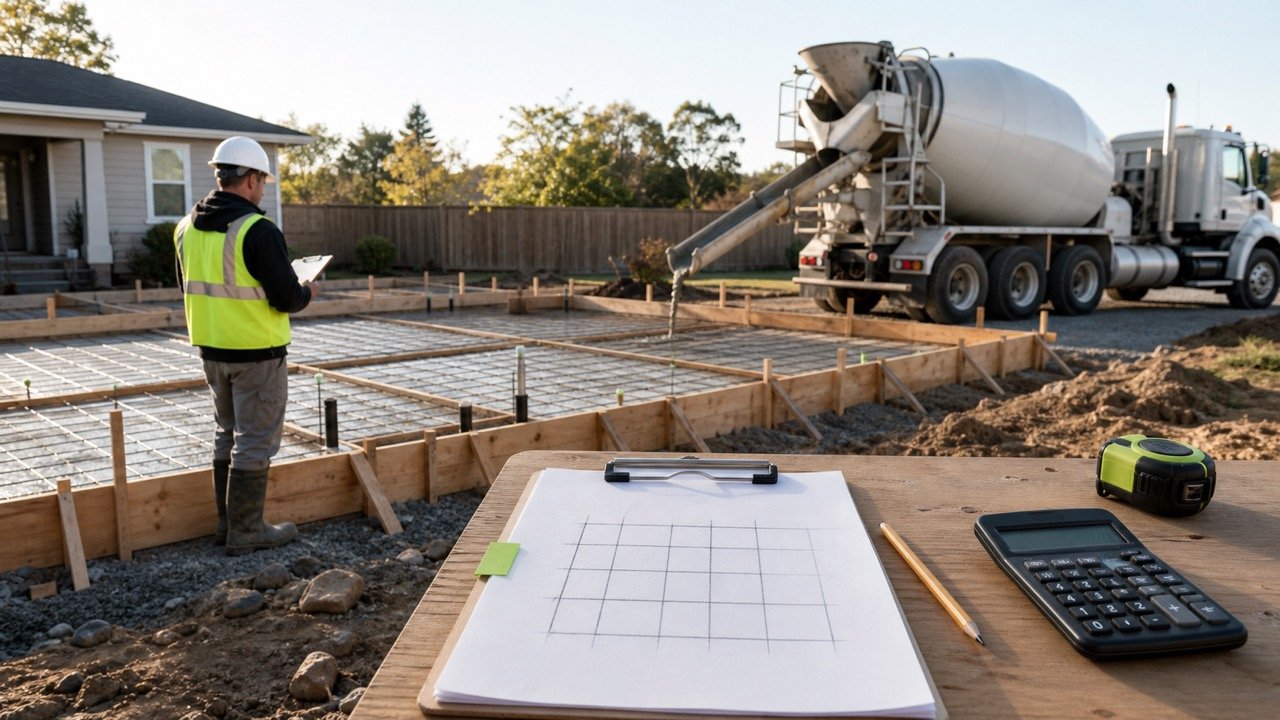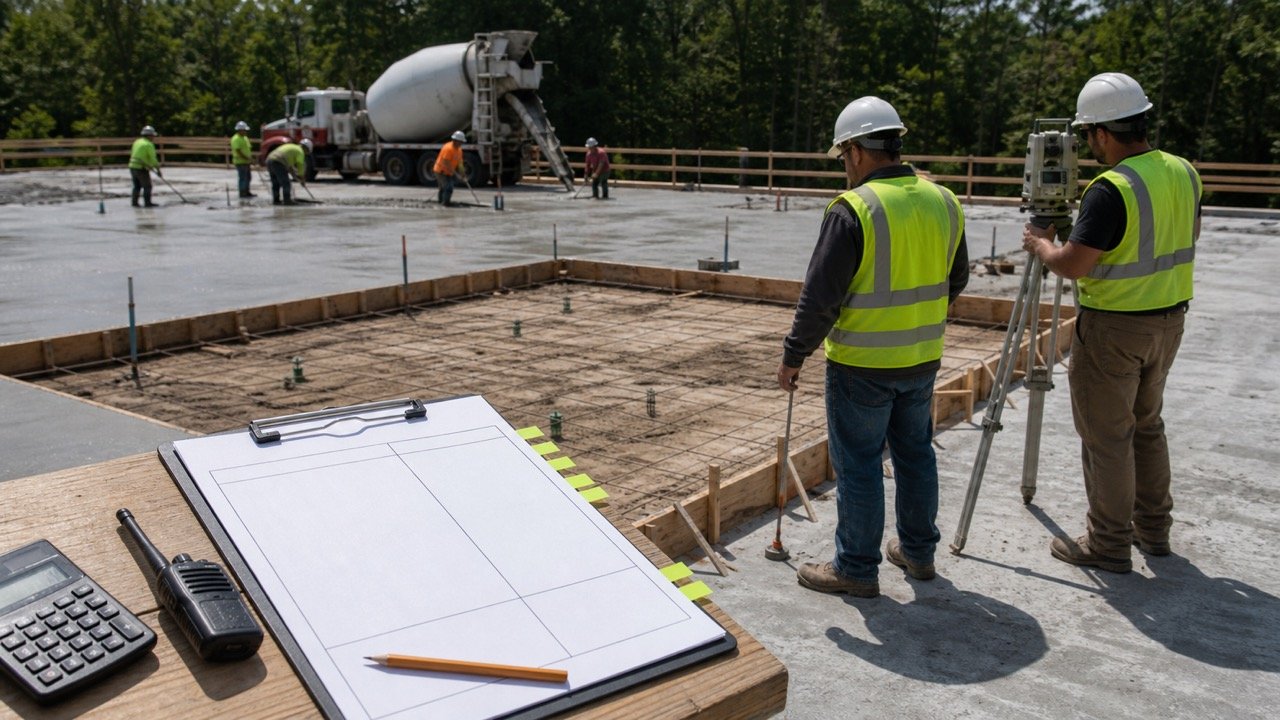
A line across a concrete slab can mark a saw cut, a formed groove, a full-depth separation, or the boundary between 2 placements. The visible line alone does not tell you which material, reinforcement, repair, or quantity belongs there.
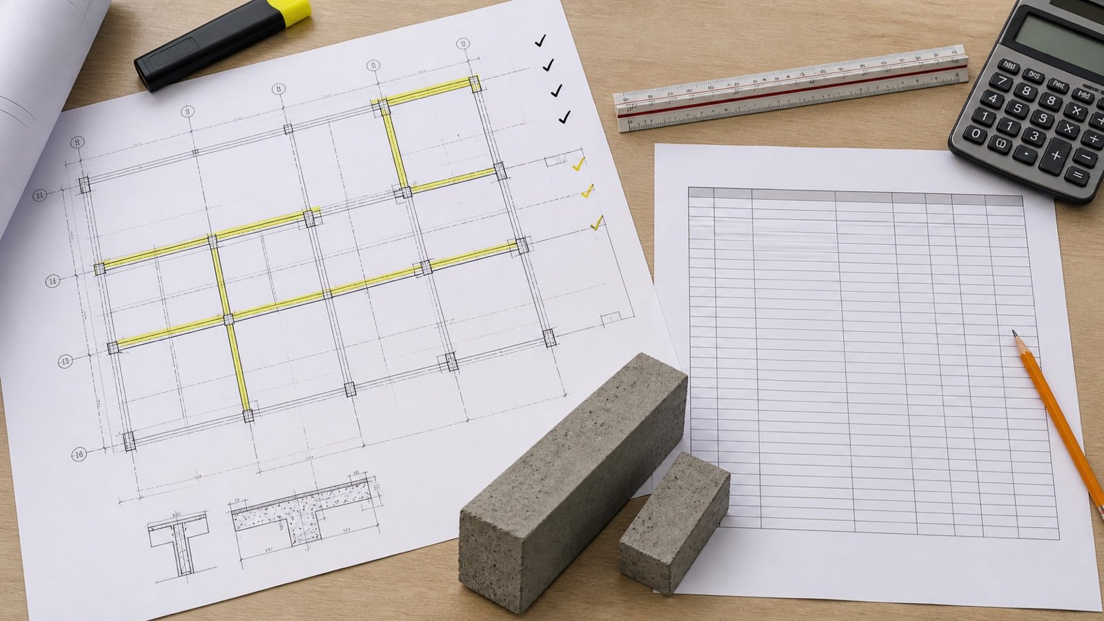
Start with the joint plan and detail callout. Check the joint's purpose, depth, continuity, reinforcement treatment, filler, sealant, load-transfer components, and adjoining construction before measuring or changing it.
What is the difference between a control joint and an expansion joint?
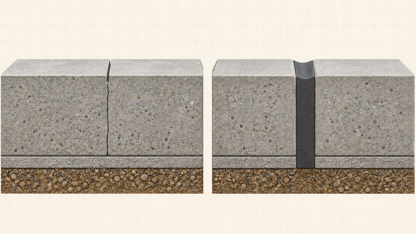
A concrete control joint creates a weakened plane so cracking caused by dimensional reduction occurs at a planned line. A concrete expansion joint separates adjoining sections so they can accommodate dimensional increases and reductions; in pavement slabs-on-ground, ACI's current terminology describes a separation filled with compressible filler.
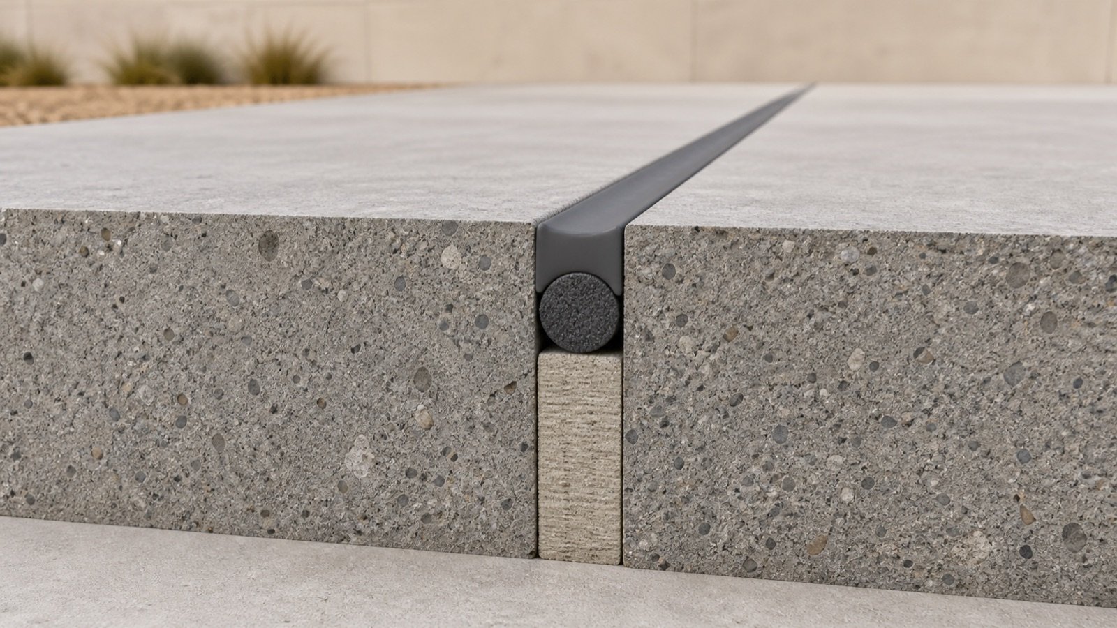
The detail is different through the slab. A control joint commonly uses a partial-depth formed, tooled, or sawed groove with concrete below it. An expansion or isolation detail creates a separation through the required depth. The project drawings decide the location, reinforcement, load transfer, width, filler, sealant, and assembly treatment.
| Check | Control or contraction joint | Expansion or isolation detail |
|---|---|---|
| Primary function | Creates a weakened plane to regulate where cracking occurs | Separates adjoining sections to permit the specified movement |
| Typical slab section | Partial-depth groove, with concrete remaining below the groove | Separation through the depth shown on the detail |
| Common creation method | Formed, tooled, sawed, or made with a joint former | Formed separation with the specified compressible filler or joint system |
| Bonded reinforcement | Read the joint and reinforcement details; the surface groove cannot prove continuity | ACI defines isolation joints with all bonded reinforcement interrupted; an expansion-joint definition allows some or all to be interrupted |
| Quantity task | Saw-cut, tooling, former, sealant, or filler scope only when specified | Full joint length, approved filler profile, sealant reservoir, backing, accessories, and separate load-transfer items |
| Main verification | Joint plan, slab detail, thickness, method, timing, panel layout, reinforcement and finish | Joint plan, movement detail, width, depth, filler, sealant, reinforcement, load transfer and adjoining assemblies |
ACI CT-25 gives separate definitions for control, contraction, isolation and expansion joints. Some slab guidance groups terms for a limited purpose. Record the drawing abbreviation and detail number before assigning a material or method.
Are control joints and contraction joints the same?
They often describe the same planned weakened-plane idea in slab work, and many drawings or contractors use the names interchangeably. Current ACI terminology lists both terms with slightly different wording.
ACI defines a control joint as a formed, sawed, or tooled groove that regulates cracking from dimensional reduction. Its contraction-joint definition refers to a formed, sawed, or tooled groove that regulates cracking from dimensional change. The applicable specification and drawing vocabulary control the project record.
Use the label written on the plan. A note that says CJ can still require a legend check because a project may use that abbreviation for control joint or construction joint.
Are isolation joints and expansion joints identical?
ACI's definitions overlap, though they are not word-for-word identical. An isolation joint separates adjacent sections for relative movement in 3 directions and interrupts all bonded reinforcement. An expansion joint accommodates dimensional increases and reductions; some or all bonded reinforcement may be interrupted.
For pavement slabs-on-ground, ACI also defines an expansion joint as a separation between slabs filled with compressible material. NRMCA CIP 6 groups “isolation or expansion joints” in its slab-on-grade explanation and lists restraints such as walls, footings, columns, adjoining slabs, stairs, and light poles.
That grouped wording supports a practical slab overview. It does not convert every building separation, pavement joint, bridge joint, wall joint, or seismic joint into the same detail.
How can you identify the joint on drawings?
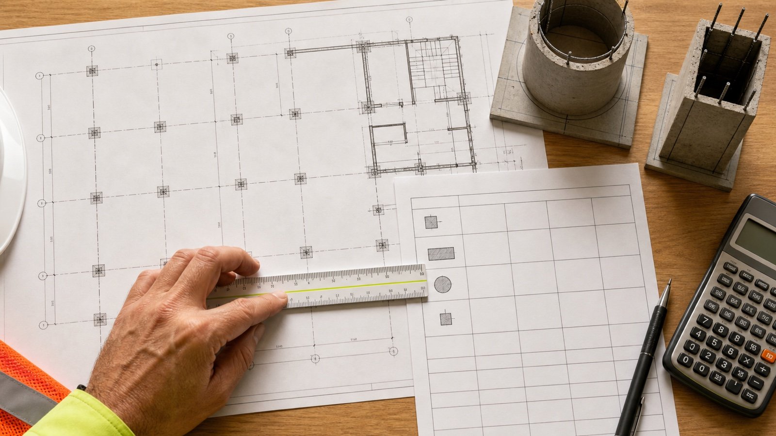
Trace the joint mark to its legend, detail reference, specification section, and material schedule. Then check the slab section and reinforcement plan at the same location.
| Drawing clue | Question to answer | Why it affects the takeoff |
|---|---|---|
| Plan abbreviation and line type | Does the legend define CJ, EJ, IJ, MJ, construction joint, or another term? | Abbreviations vary by project |
| Section through the slab | Is the detail a partial groove or a full-depth separation? | Cutting, filler and sealant scopes differ |
| Reinforcement detail | Which bars, mesh, dowels, sleeves or ties cross the location? | Surface appearance cannot establish structural continuity |
| Joint material schedule | Which filler, backer, primer, sealant, cover or edge protection is specified? | Length alone cannot produce a purchase quantity |
| Finish and waterproofing details | Does the joint continue through a topping, coating, tile, membrane, wall or roof assembly? | Each assembly may have its own movement and continuity detail |
| Revision and field condition | Does the installed location match the current issued drawing? | A changed width, route or joint type changes quantities |
Keep unresolved details as open items in the takeoff. Do not infer missing reinforcement or movement requirements from a nearby typical detail unless the contract documents apply it to that location.
How can you identify an existing joint in the field?
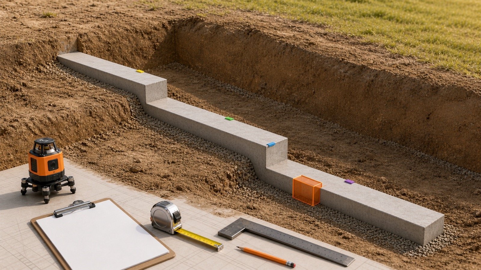
Measure the visible width and trace the line to edges, columns, walls, adjoining slabs, penetrations, and other restraints. Photograph the surface condition and compare it with the as-built drawings, repair records, joint schedule, and specifications.
A narrow groove may indicate a sawed or tooled control joint. A wider filled line may indicate an isolation or expansion joint. Sealant can cover either type, and a previous repair can hide the original profile. A surface inspection cannot confirm the full depth, reinforcement, dowels, sleeves, filler, bond breaker, or substrate condition.
Use nondestructive investigation or a controlled opening only when the responsible team specifies it. Scanning, cutting, coring, removal, and repair each require a location-specific safety and technical plan.
Which spacing and depth rules apply to control joints?
NRMCA CIP 6 gives slab-on-grade contraction-joint guidance. It recommends maximum spacing of 24 to 36 times slab thickness, a maximum of 15 ft (4.5 m), square or nearly square panels, and a panel length no more than 1.5 times its width.
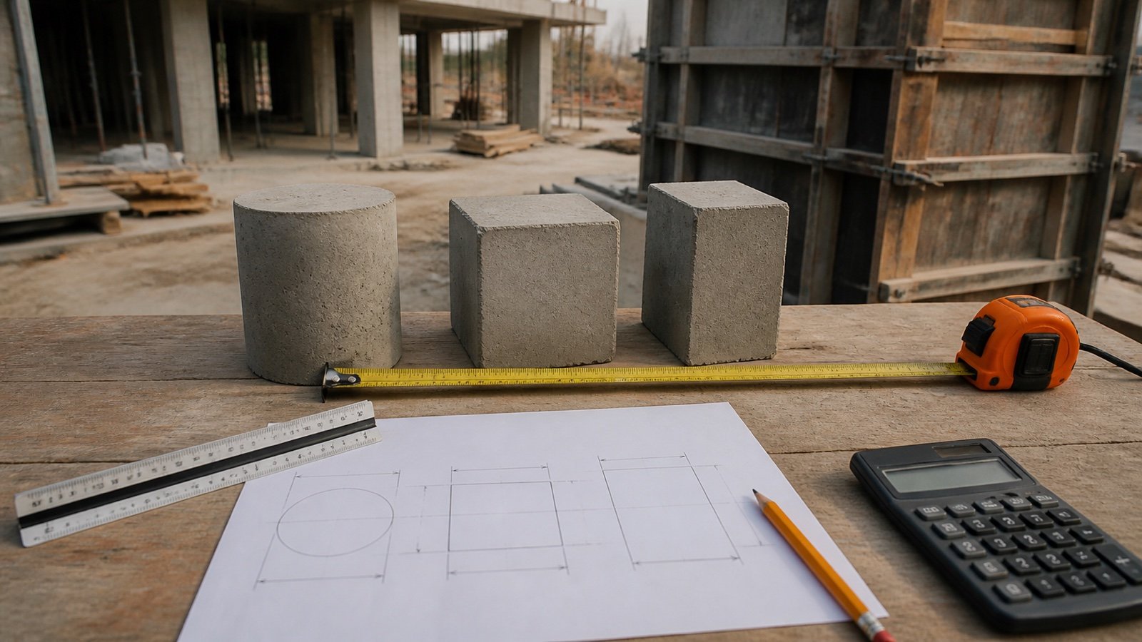
For a 4 in (100 mm) slab, 24 to 36 thicknesses equal 8 to 12 ft (2.4 to 3.6 m). CIP 6 uses about 10 ft (3 m) for that example. The note gives a contraction-joint groove depth of at least one-quarter of slab thickness and not less than 1 in (25 mm).
| Check | US customary | Metric |
|---|---|---|
| Slab thickness | 4 in | 100 mm |
| 24 × thickness | 96 in = 8 ft | 2400 mm = 2.4 m |
| 36 × thickness | 144 in = 12 ft | 3600 mm = 3.6 m |
| Quarter-depth check | 1 in | 25 mm |
These figures explain the cited contraction-joint guidance. Mix design, aggregate, slab geometry, reinforcement, subgrade, restraint, loads, finish, environment, construction method, specification, and professional design can change the joint plan.
Why can't that spacing rule set expansion-joint locations?
The 24-to-36-thickness rule in CIP 6 belongs to contraction-joint spacing. Expansion and isolation locations respond to restraints, movement, structure type, adjoining construction, and the designed separation.
ACI PRC-224.3's public scope separates guidance by buildings, bridges, slabs-on-ground, pavements, tunnels, walls, liquid-retaining structures, and mass concrete. One fixed expansion-joint distance cannot represent all those systems.
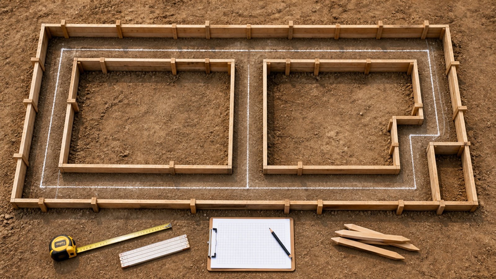
Use the approved joint plan. If the plan omits a required location or conflicts across disciplines, send a documented request for clarification before placing concrete or ordering a joint system.
When should a control joint be cut?
NRMCA CIP 6 says timing depends on the method and the concrete's setting characteristics. It lists early-entry dry cutting at about 1 to 4 hours after finishing and conventional saw cutting within 4 to 12 hours after finishing.
Cutting too early can ravel the edges. Waiting too long can allow uncontrolled cracking before the cut. Those ranges are planning guidance from the cited slab-on-grade note, not a countdown that overrides weather, mixture behavior, equipment, specifications, test panels, or the responsible crew's approved procedure.
Expansion or isolation material is planned into the formwork and joint detail. A later saw cut across a finished slab does not create the same full-depth separation.
How do construction joints and cold joints differ?
A construction joint is an intentional interface between concrete placements. NRMCA says it commonly occurs at the end of a day's work or after a stoppage lets the previous concrete set and harden; the joint may be designed for movement, load transfer, bond, or reinforcement continuity.
ACI defines a cold joint as a discontinuity caused by a delay long enough to prevent intermingling and bonding. The 2 terms record different causes. A planned placement break needs its construction-joint detail, while an unplanned discontinuity needs project-specific evaluation.
A construction joint can coincide with another planned joint line when the drawings provide a combined detail. Do not merge the quantities or reinforcement assumptions without that detail.
Which materials belong to each joint type?
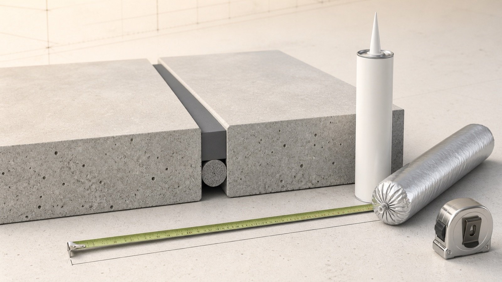
The joint schedule controls the materials. A control joint may remain open, receive sealant, use a semi-rigid filler, or require another treatment based on traffic, exposure, finish, hygiene, waterproofing, and maintenance needs.
An isolation or expansion detail may include compressible filler, a sealant reservoir, backer or bond breaker, primer, edge protection, waterstop, cover system, dowels or sleeves, and assembly-specific continuity components. Each item has a different unit and specification.
| Item | Quantity basis | Required evidence |
|---|---|---|
| Saw cutting or tooling | Joint length, cut depth, method and passes | Control-joint plan and procedure |
| Compressible filler | Length, height, thickness, roll or sheet cutting | Isolation or expansion detail and product data |
| Field sealant | Installed length × width × sealant depth, adjusted to product yield | Joint profile and current product data |
| Backer or bond breaker | Length and approved size or form | Sealant-system detail |
| Dowels, sleeves or load-transfer assemblies | Count, spacing, size, coating and orientation | Structural detail and schedule |
| Cover, membrane or fire-rated system | Joint length and complete assembly | Architectural and manufacturer system detail |
Use the Expansion Joint Calculator after the approved full-depth joint route, sealant width and depth, package volume, filler length, and allowance are known. It calculates material quantity and does not create the joint design.
Can you fill or repair both joints the same way?
Identify the joint and expected movement before choosing a repair. A rigid patch across a movement separation can restrain the joint or crack. A flexible sealant placed into an unprepared groove can lose adhesion, tear, collect debris, or leave the required edge support unresolved.
Record the existing width and depth by section, movement history, edge damage, moisture, contaminants, traffic, temperature, previous materials, substrate condition, and adjoining finish. Obtain the approved preparation, backing, primer, sealant profile, cure, reopening, and compatibility requirements for the selected system.
Repairs at leaking, fire-rated, traffic-bearing, structural, seismic, waterproofed, or multi-assembly joints need the applicable system detail and qualified review. A product name or hardness category does not prove suitability.
Common control-joint and expansion-joint mistakes
- Reading CJ without checking the drawing legend.
- Calling every filled line an expansion joint.
- Calling every saw cut a complete separation.
- Applying a contraction-joint spacing rule to expansion joints.
- Assuming reinforcement continuity from the finished surface.
- Using isolation and expansion as universal synonyms across structures.
- Measuring sealant length before grouping different widths and depths.
- Counting shared boundaries twice in a slab takeoff.
- Installing a rigid repair across a joint intended to move.
- Ignoring the joint where a topping, tile, membrane, wall, or roof crosses it.
The Concrete Planning hub links quantity tools for concrete, reinforcement, blocks, bags, and ready-mix. Use the Rebar Calculator only for an approved grid; the joint detail decides whether reinforcement continues or stops.
Safety and design limits
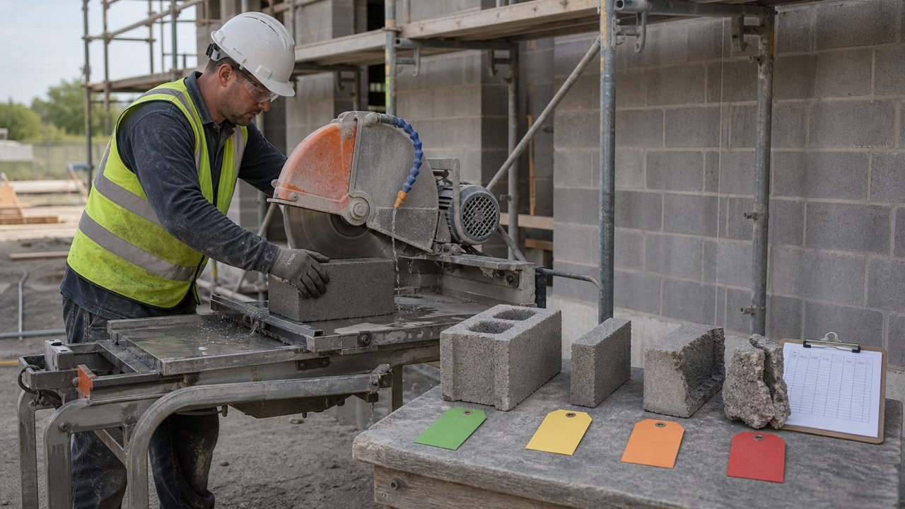
Concrete cutting, grinding, routing, removal, drilling, and joint cleaning can expose workers to silica, blades, noise, electricity, water, debris, traffic, hidden reinforcement, utilities, chemicals, lifting, and restricted access. For United States construction workplaces, OSHA 29 CFR 1926.1153 lists specified exposure-control methods for handheld and walk-behind saw tasks.
Follow the current drawings, specifications, product labels and safety data sheets, equipment instructions, exposure-control plan, traffic control, lockout requirements, permits, and qualified supervision. Scan or otherwise clear the cut path where hidden services, reinforcement, tendons, dowels, or embedded systems may be present.
This guide supports identification and quantity planning. It does not approve joint location, spacing, width, depth, reinforcement, load transfer, structural separation, fire rating, waterproofing, sealant, repair, or code compliance.
Sources and source scope
- ACI CT-25: 2025 ACI Concrete Terminology: current ACI definitions for control, contraction, isolation, expansion, construction and cold joints, plus filler and sealant terminology.
- ACI joint terminology FAQ: concise distinction among contraction, isolation, expansion, construction and cold joints.
- NRMCA CIP 6: Joints in Concrete Slabs on Grade: slab-on-grade joint purposes, common restraint locations, contraction-joint spacing, panel shape, depth and timing guidance.
- ACI PRC-224.3-95, reapproved 2013: public scope covering different concrete structures, movement conditions, jointing techniques and sealants.
- Sika Emseal joint comparison: manufacturer context for control joints and full building movement-joint systems.
- OSHA 29 CFR 1926.1153: United States construction silica scope and specified control methods for concrete saw tasks.
Source scope: ACI and NRMCA support the named terminology and slab guidance. Sika Emseal supports building movement-system context. OSHA supports the stated United States workplace rule. Project drawings, specifications, local requirements, product data, field conditions, safety plans, and responsible professionals govern the installed work.
Review note: Saleem Sial owns the research and editorial record. Source checks, arithmetic checks, build validation, link crawl, schema review, and rendered QA form the internal publication gate. Waseem Sial, External Reviewer and Engineer, is listed for ongoing external review; no completed review date is claimed.