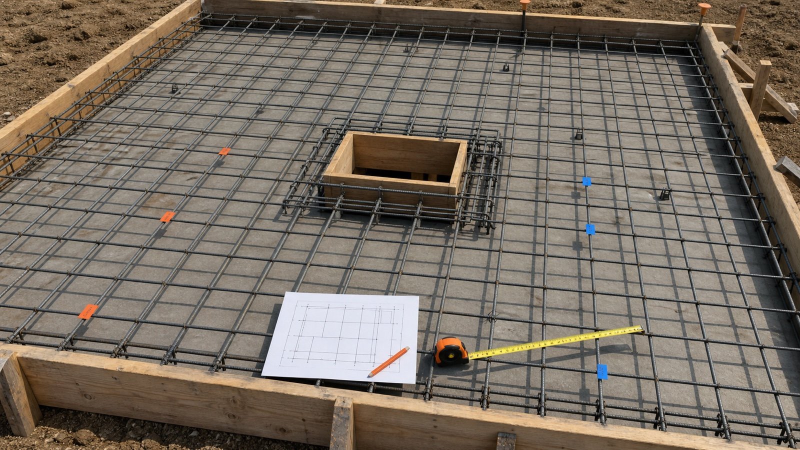
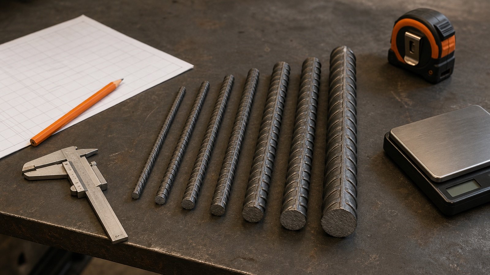
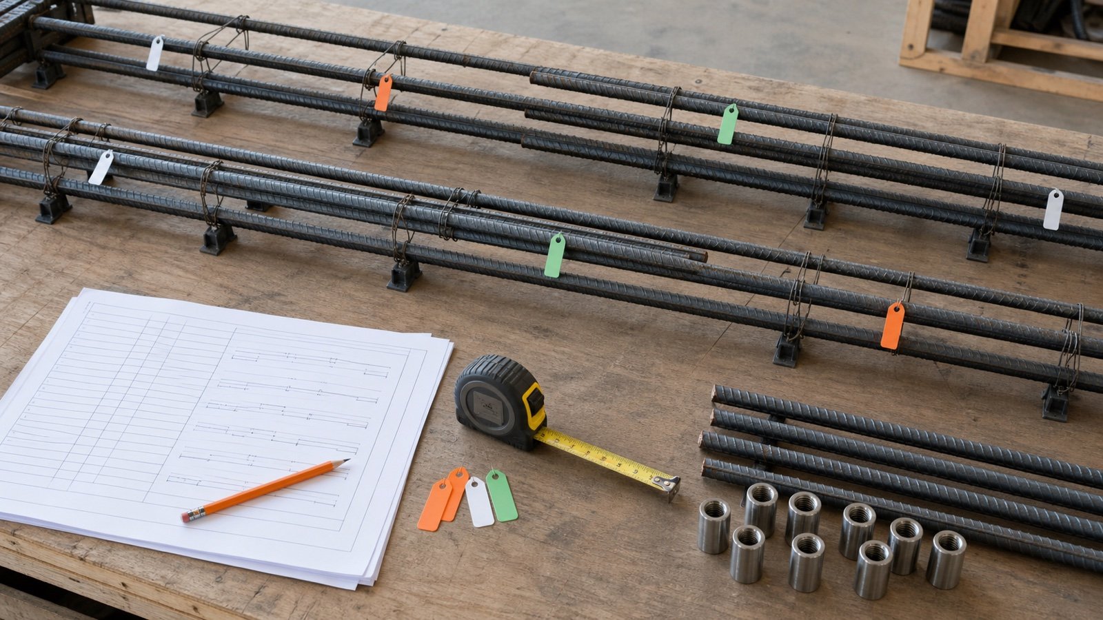
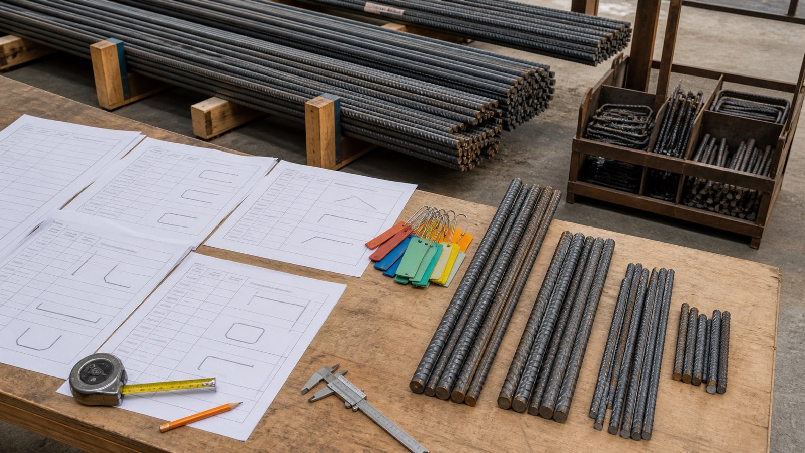
A slab rebar takeoff must count bars in both directions before it converts length into stock. Use the slab rebar measurement guide to mark drawing zones, layers, openings and bar lines before entering a uniform grid.
This calculator gives each direction its own count and resulting spacing. It separates installed grid length, lap-added cut length, allowance, minimum pooled stock length, and line-by-line pieces. Check the Rebar Size and Weight Chart for #3–#18 properties, use the rebar cutting-list guide to test whole-piece stock patterns, and reconcile approved lap or coupler junctions with the rebar splice takeoff guide.
How much rebar does your rectangular grid need?
Enter the slab dimensions, the offset from each concrete edge to the first and last bar centerlines, and the maximum center-to-center spacing in each direction. The calculator rounds the number of gaps upward so the displayed equal spacing does not exceed your entered maximum.
Stock and mass outputs appear only from values you enter. The tool does not select the bar, grade, spacing, cover, lap, splice location, stock length, or allowance.
What does the rebar calculator include?
The calculator covers one rectangular, uniformly spaced, single mat with straight bars. Bars run parallel to the slab length and width, forming a grid between 4 entered centerline offsets.
| Result | Calculation stage | Meaning |
|---|---|---|
| Directional bar counts | Clear spacing span divided by maximum spacing, rounded up, plus 1 | Number of straight bar lines in each direction |
| Actual equal spacing | Clear spacing span divided by the resulting number of gaps | Check that generated spacing stays at or below the entered maximum |
| Installed grid length | Bar count × clear bar length in both directions | Steel length in the completed unspliced grid geometry |
| Cut length with laps | Installed length plus entered lap at every calculated stock splice | Required cut length before allowance |
| Minimum pooled stock equivalent | Allowance-adjusted cut length divided by stock length, rounded up | Lower length bound when useful offcuts can serve other cuts |
| Line-by-line pieces | Pieces required for every bar run without sharing offcuts | Upper piece count before a cut plan reuses offcuts |
Which slab and grid measurements do you need?
Use one drawing revision and one consistent unit system. Record the mat mark, slab limits, bar direction, bar designation, spacing note, centerline offsets, openings, edge details, and any zones that use another layout.
Overall slab length and width
Enter the concrete plan dimensions for the rectangular grid limits. A construction joint, thickened strip, opening, recess, column zone, or separate pour can change the reinforcement layout even when the outer concrete remains rectangular.
Split non-rectangular slabs and layout changes into drawing-based regions. Do not subtract an opening as area and expect the bar lines to resolve themselves. Bars may stop, continue, trim, anchor, or receive added reinforcement around that opening.
Bar-centerline edge offset
The calculator needs the plan distance from each slab edge to the centerline of the first or last bar. It uses one equal offset on all 4 edges.
Structural documents often state concrete cover as a clear distance from the concrete surface to the outside of the reinforcement. That clear cover is not the same geometric measurement as a centerline offset. Use the approved placing dimension or convert only with the correct bar size, orientation, coating, tolerance, and detailing instructions.
Maximum spacing in each direction
Enter the approved maximum center-to-center spacing for bars running parallel to the slab length and width. Long-running bars are spaced across the clear width. Width-running bars are spaced across the clear length.
Use 2 entries when the drawing specifies different spacing by direction. Zones with banded, alternating, added, or changing spacing need a bar-by-bar takeoff.
Why does the formula round the number of gaps upward?
A maximum spacing is an upper limit for the generated grid. Ceiling division adds enough gaps to keep the equal spacing at or below that limit.
Bar count = ceiling(clear spacing span ÷ maximum spacing) + 1
Example: a 3.9 m clear spacing span with a 200 mm maximum needs 20 gaps and 21 bars. The actual equal spacing is 3.9 ÷ 20 = 0.195 m, or 195 mm.
Floor division would give 19 gaps and 20 bars. Equal distribution would then produce about 205.3 mm, exceeding the entered 200 mm maximum. A placing drawing with fixed offsets, residual end spaces, staggered bars, or explicit marks governs instead of this uniform distribution.
Which formulas does the rebar calculator use?
The calculator converts millimetres or inches to the selected base length before it counts gaps. NIST defines 1 ft as 0.3048 m exactly and 1 in as 25.4 mm exactly.
Clear length = slab length − 2 × bar-centerline offset
Clear width = slab width − 2 × bar-centerline offset
Long bars = ceiling(clear width ÷ long-bar maximum spacing) + 1
Short bars = ceiling(clear length ÷ short-bar maximum spacing) + 1
Installed length = long bars × clear length + short bars × clear width
Intersections = long-bar count × short-bar count
The intersection result counts crossings. It does not calculate tie-wire quantity, because the tying method, tie frequency, tail length, wire size, supports, and fabrication practice come from the work plan.
Worked metric rebar-grid example
A rectangular slab is 6 m long and 4 m wide. The approved layout places outer bar centerlines 50 mm from the slab edges and limits spacing to 200 mm in both directions.
- Clear length: 6 − 2 × 0.05 = 5.9 m.
- Clear width: 4 − 2 × 0.05 = 3.9 m.
- Long bars: ceiling(3.9 ÷ 0.2) + 1 = 21 bars, each 5.9 m.
- Actual long-bar spacing: 3.9 ÷ 20 = 195 mm.
- Width-running bars: ceiling(5.9 ÷ 0.2) + 1 = 31 bars, each 3.9 m.
- Actual short-bar spacing: 5.9 ÷ 30 = 196.667 mm.
- Installed grid length: 21 × 5.9 + 31 × 3.9 = 244.8 m.
- Grid intersections: 21 × 31 = 651.
The user then enters 12 m stock, a 600 mm approved lap, and 5% planning allowance. No grid run exceeds one stock bar, so the lap adds 0 m. Planning cut length is 257.04 m.
The minimum pooled-length equivalent is 22 stock bars. The line-by-line count before offcut reuse is 52 pieces. A cut plan can test whether 22 bars can produce the required 21 cuts at 5.9 m and 31 cuts at 3.9 m.
Worked imperial rebar-grid example
A slab is 20 ft × 12 ft. The bar centerlines sit 3 in from each edge and both maximum spacings are 12 in.
- Clear dimensions are 19.5 ft × 11.5 ft.
- Bars running 19.5 ft: ceiling(11.5 ÷ 1) + 1 = 13.
- Bars running 11.5 ft: ceiling(19.5 ÷ 1) + 1 = 21.
- Installed length: 13 × 19.5 + 21 × 11.5 = 495 ft.
- Intersections: 13 × 21 = 273.
With 20 ft stock, a 24 in entered lap, and 10% allowance, neither direction needs a splice. Planning cut length is 544.5 ft. The minimum pooled-length equivalent is 28 stock bars; the no-offcut-reuse count is 34 pieces.
An entered unit mass of 0.668 lb/ft gives 330.66 lb installed. The 28-bar minimum stock equivalent weighs 374.08 lb at that entered rate.
How does the calculator add lap length?
The calculator accepts an approved lap and adds it at each splice created by the entered stock length. It does not calculate a code lap.
Pieces per run = ceiling((run length − lap) ÷ (stock length − lap))
Required cut length per run = run length + (pieces − 1) × lap
CRSI explains that lap length varies with concrete strength, concrete type, bar grade, bar size, spacing, cover, and confinement. The engineer identifies lap locations and lengths on structural drawings; placing drawings and project notes carry those requirements into fabrication.
A 30 m clear run using 12 m stock and a 600 mm approved lap needs 3 pieces because each added piece advances 11.4 m after the overlap. The required cut length is 30 m plus 2 laps, or 31.2 m.
What do the 2 stock results mean?
Stock length alone cannot produce an exact purchase count without a cut plan. Bar lengths, repeated cuts, lap pieces, offcut sizes, bend marks, splice staggering, supplier lengths, and fabrication rules determine which offcuts remain useful.
| Stock result | Assumption | Use |
|---|---|---|
| Minimum pooled-length equivalent | All allowance-adjusted cut length can be pooled and divided by full stock length | Lower length bound; it may be unattainable when cuts do not nest |
| Line-by-line pieces | Every grid line receives its calculated pieces and no offcut serves another line | Upper count before offcut reuse; it can overstate an efficient order |
| Approved cut plan | Fabricator or estimator assigns actual cuts, marks, laps, bends, and reusable offcuts | Procurement and fabrication record |
Use the 2 calculator values to check the range. Build a cutting schedule before ordering when the range is material to cost, transport, handling, or site storage.
How should planning allowance be applied?
The calculator applies the entered percentage after installed length and calculated laps. It does not hide laps inside the allowance.
Planning cut length = cut length including laps × (1 + allowance % ÷ 100)
Record the reason and source for the percentage. Cutting pattern, damage, changes, rejected pieces, test pieces, and retained offcuts affect project use in different ways. Reconcile returned and reusable steel rather than treating every offcut as waste.
How should rebar mass be calculated?
Enter the mass per unit length for the exact bar designation and specification. Metric mode expects kg/m; imperial mode expects lb/ft.
ASTM A615/A615M-26 covers carbon-steel reinforcing bars in standard sizes, grades, cut lengths, and coils. Caltrans publishes an ASTM reinforcing-bar reference table with nominal diameter, area, and lb/ft values. The project specification and supplier documentation identify the applicable product.
The calculator multiplies installed length by the entered rate. When stock length is present, planning mass uses the minimum whole-stock equivalent. It does not include chairs, supports, tie wire, couplers, welded assemblies, delivery packaging, or another bar mark.
Can the calculator choose bar size, spacing, or cover?
The calculator uses the values you enter. Structural design determines reinforcement area, bar size, grade, spacing, layers, location, cover, development, anchorage, splices, crack control, durability, and construction details.
A slab may contain top and bottom mats, column strips, middle strips, edge bars, trimmer bars, dowels, hooks, chairs, openings, thickened regions, and local additions. Calculate each approved bar mark from the drawings and bar schedule.
Use the concrete footing volume guide for concrete geometry. Rebar cages, stirrups, steps, corners, and longitudinal footing bars need a separate reinforcement takeoff.
Which conditions need a bar-by-bar takeoff?
| Condition | Why the uniform grid does not fit |
|---|---|
| Opening or penetration | Bars may stop, trim, continue, offset, or receive added reinforcement |
| Top and bottom mats | Each face can use different bars, spacing, laps, and extents |
| Banded or column-strip reinforcement | Spacing and bar lengths change by zone |
| Bent bars, hooks, dowels, or stirrups | Cut length needs bend geometry, hooks, and bar marks |
| Footing, beam, wall, or cage | Longitudinal bars and transverse reinforcement follow another layout |
| Staggered or restricted splices | Splice locations cannot be inferred from stock length alone |
| Construction joint or separate pour | Development, continuation, couplers, and dowels affect the line |
What handling and safety checks remain?
Confirm stock lengths, bundle mass, unloading method, lifting points, storage supports, site access, cut-and-bend responsibilities, and fabrication tolerances with the supplier and site team.
For United States construction workplaces, OSHA 29 CFR 1926.701(b) requires employers to guard protruding reinforcing steel where a fall could cause impalement. Quantity output does not establish the required protection, lifting plan, work platform, personal protective equipment, or site controls.
Follow the rules and project process for the work location. Bar bundles and long pieces can exceed manual-handling and vehicle limits even when the calculator's length arithmetic is correct.
Common rebar quantity mistakes
- Using floor division when the entered spacing is a maximum.
- Calling a clear-cover note a centerline offset without the required conversion.
- Counting bars in the direction they run instead of across the direction they are spaced.
- Using one spacing for zones that have different drawing requirements.
- Subtracting an opening by area without resolving each affected bar line.
- Using a standard lap multiple instead of the approved lap and location.
- Dividing total length by stock length and calling the result an exact purchase count.
- Assuming every offcut is reusable or every offcut is waste.
- Using a unit mass from another designation, specification, coating, or product.
- Combining chairs, dowels, couplers, tie wire, and separate bar marks with the grid result.
What should the rebar quantity record contain?
- Project, element, pour, grid or mat mark, drawing revision, date, and preparer.
- Overall slab dimensions, grid limits, openings, and excluded zones.
- Bar designation, grade, coating, direction, face or layer, and applicable specification.
- Centerline edge offsets, maximum spacing, calculated bar counts, and actual spacing.
- Clear bar lengths and installed length by direction.
- Approved splice locations and laps, stock length, and cut length with laps.
- Allowance reason, minimum stock equivalent, no-reuse count, and approved cut plan.
- Unit mass source, installed mass, order mass, bundle and delivery records.
- Unresolved design, fabrication, handling, safety, and field-change items.
Use the Ready-Mix Concrete Calculator for concrete order volume and the Concrete Bags Calculator for package-yield planning. The concrete planning hub keeps concrete and reinforcement quantities in one workflow.
Sources and scope
- ASTM A615/A615M-26: current carbon-steel reinforcing-bar scope, sizes, grades, cut lengths, coils, and separate unit systems.
- Caltrans Bridge Design Details 13.1: published ASTM reinforcing-bar designation, diameter, area, and lb/ft reference data.
- CRSI Splicing Bars: design variables that affect lap length and the role of drawings in splice length and location.
- NIST Guide to the SI, Appendix B: exact international-foot and inch conversions.
- OSHA 29 CFR 1926.701: United States protruding-rebar impalement protection context.
Source scope: ASTM and Caltrans support product-standard and reference-property context. CRSI supports the dependence of lap requirements on design variables. NIST supports unit conversion. OSHA supports the named United States workplace rule. Structural drawings, calculations, specifications, placing drawings, bar lists, supplier records, fabrication plans, site controls, and responsible professionals govern the work.
Review note: Saleem Sial owns the research and editorial record. Formula fixtures, source checks, build validation, and rendered QA form the internal publication gate. Waseem Sial, External Reviewer and Engineer, is listed for ongoing external review; no completed review date is claimed.