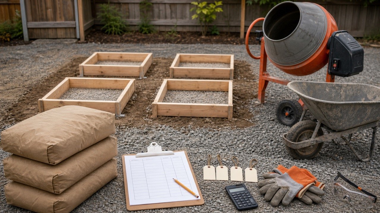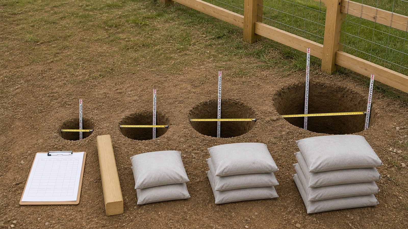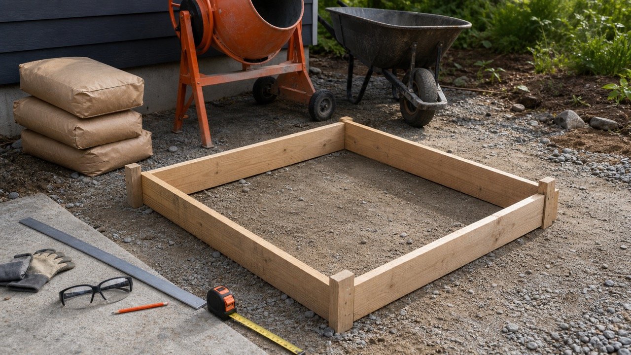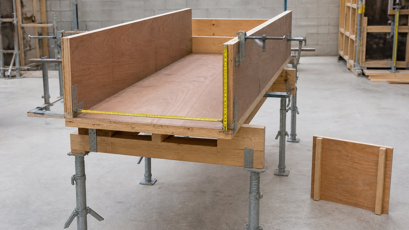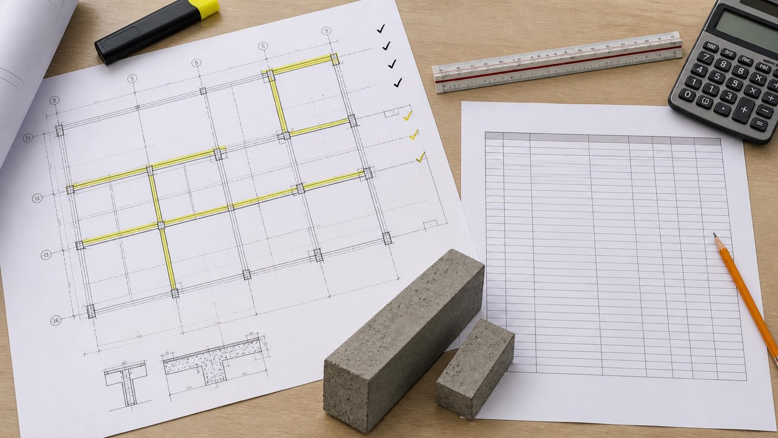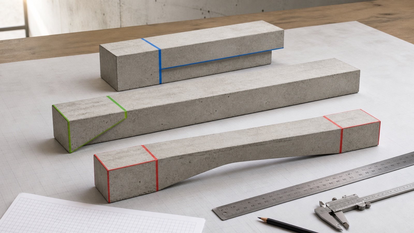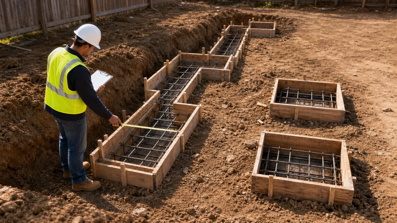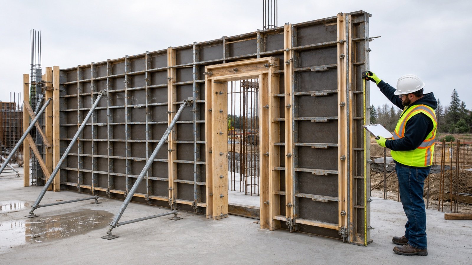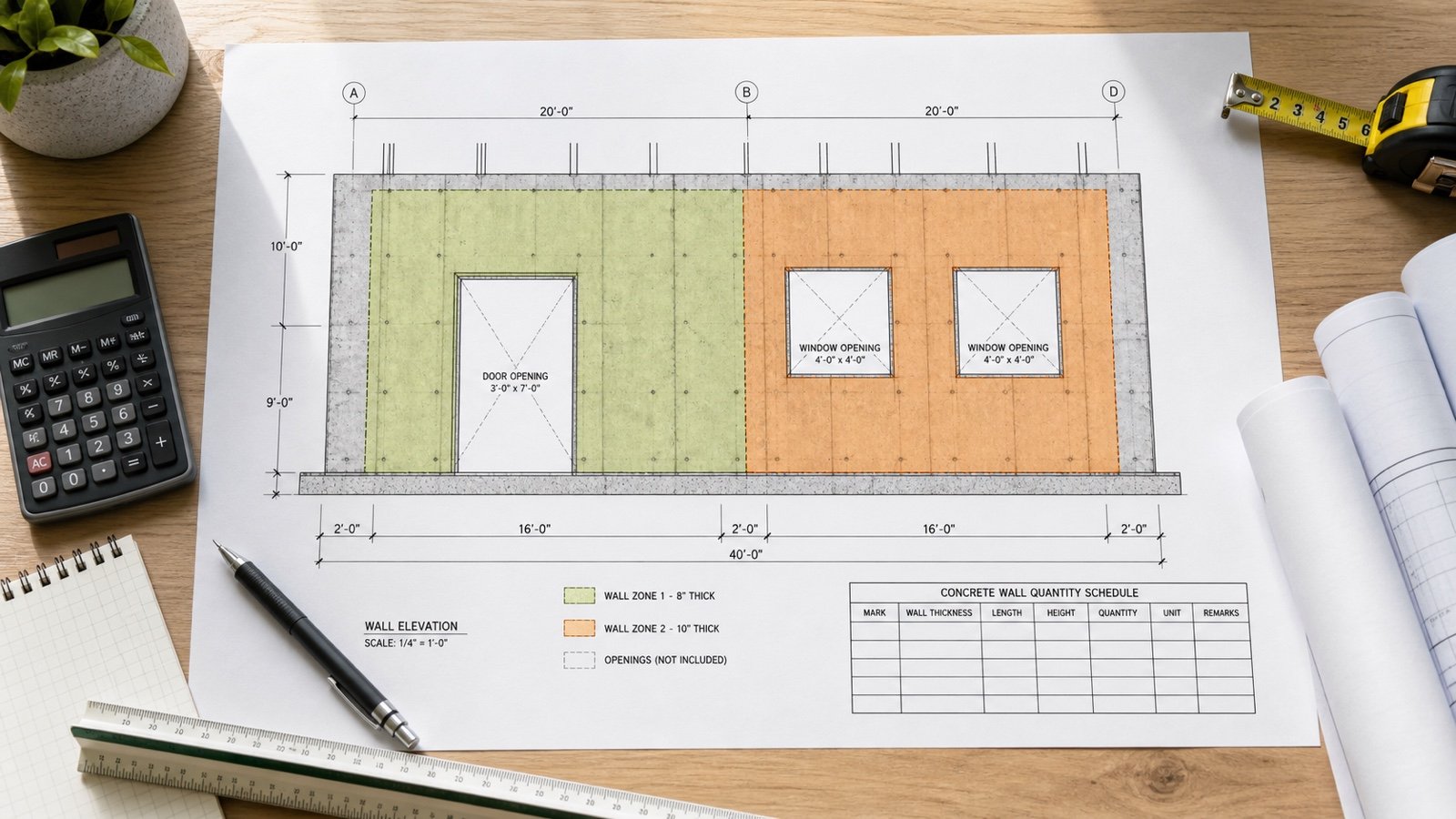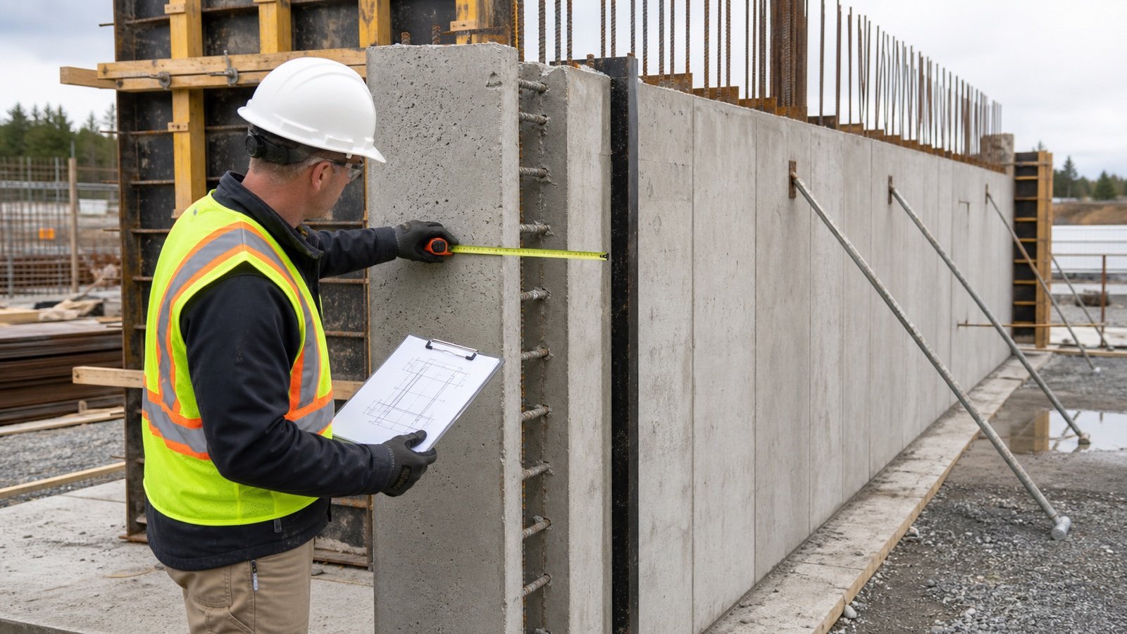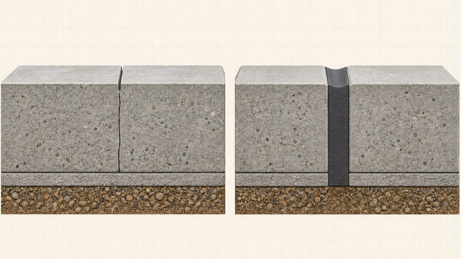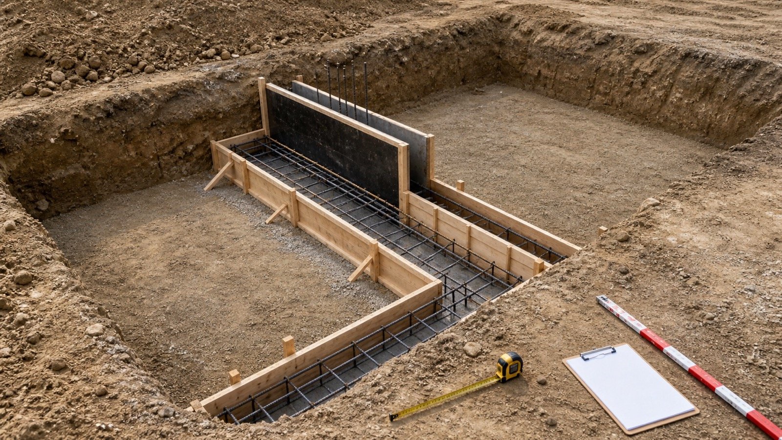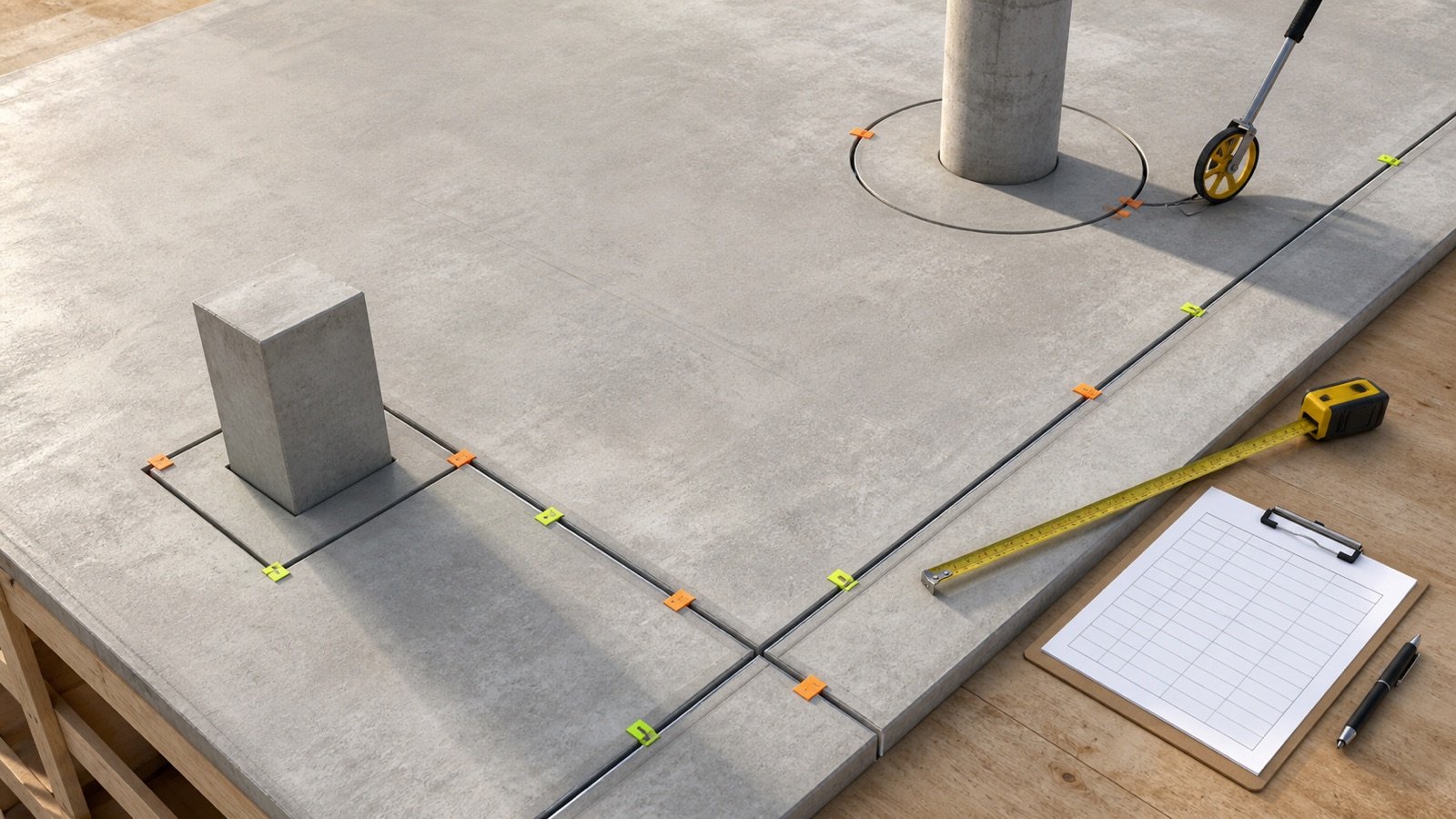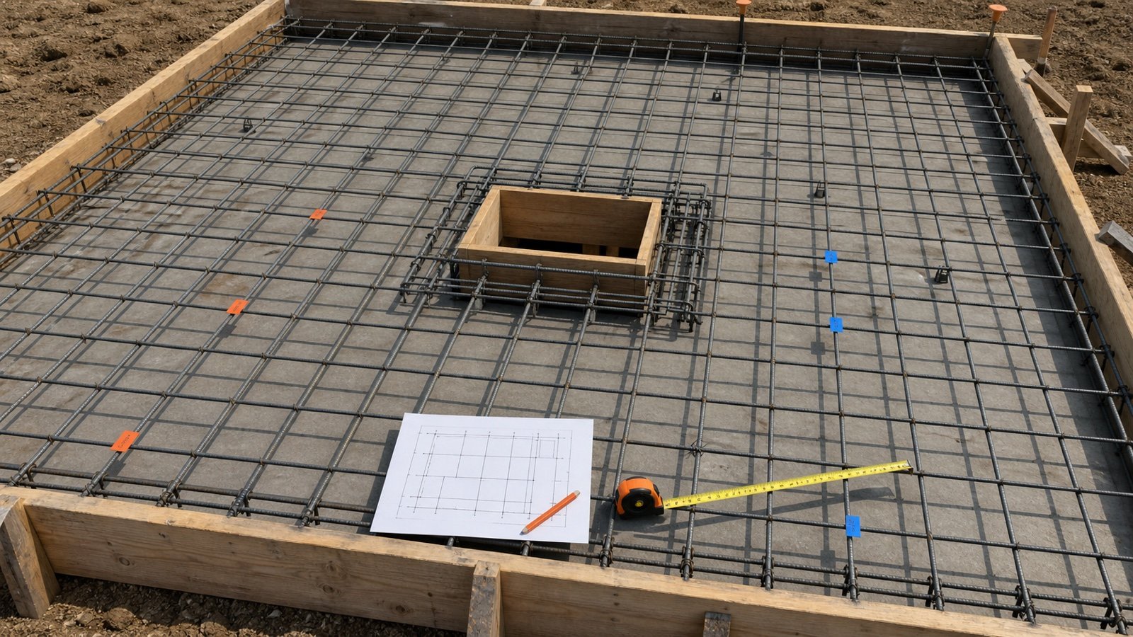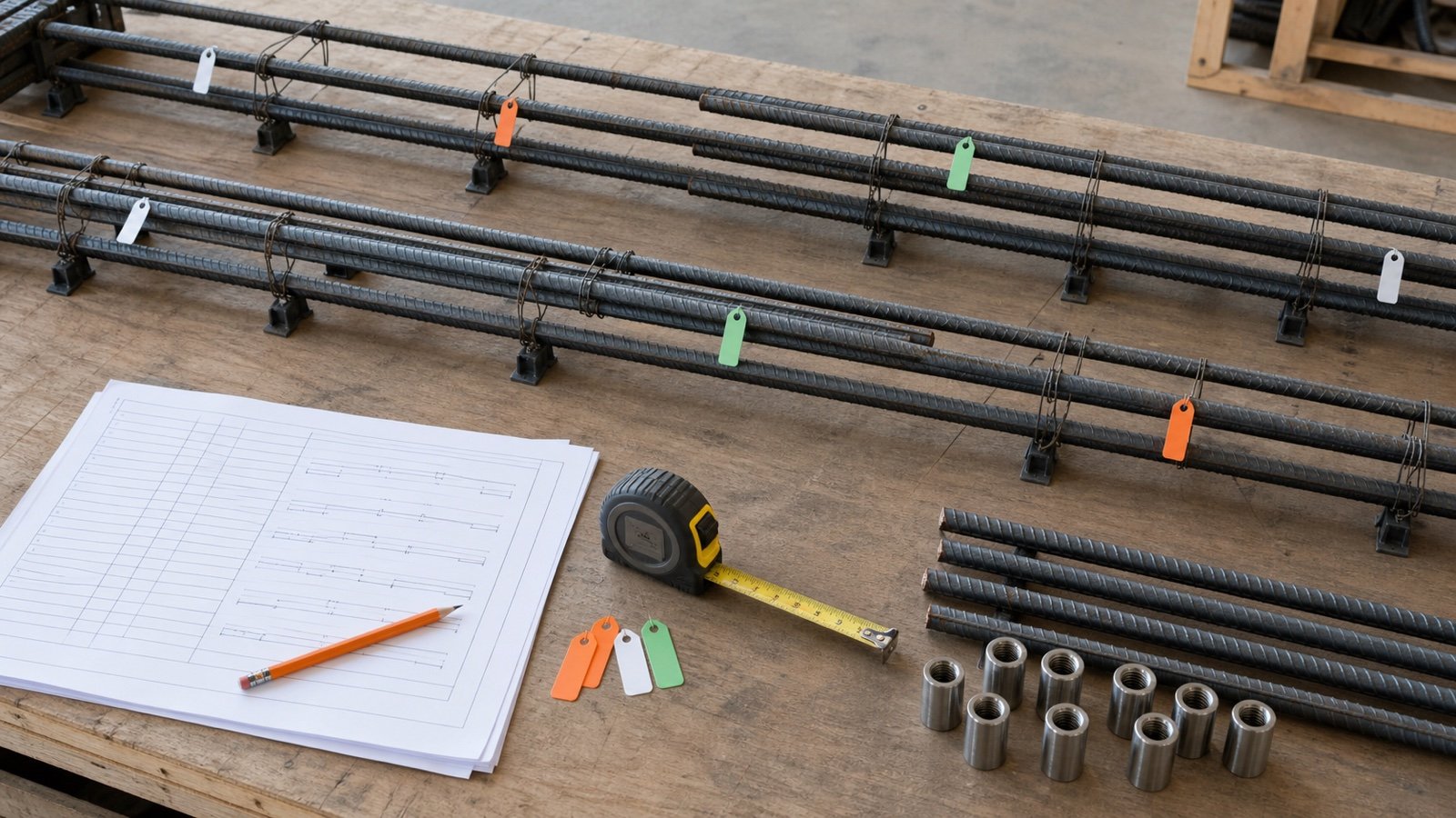
A rebar splice takeoff begins with the approved splice schedule, detail or placing note. Record the bar mark, location and connection type before adding steel length or counting couplers.
The arithmetic can check a quantity. Structural documents and responsible professionals set the lap, splice type, location, staggering and product requirements.
How do you calculate rebar splice quantities?
Count each approved bar junction once. For a lap splice, multiply the junction count by the approved lap length to find added steel. For a mechanical splice, count one accepted coupler assembly at each approved junction and keep its product record separate from bar length.
CRSI states that the architect or engineer provides splice location, lap length and related information on structural drawings. It also explains that lap length changes with concrete, bar, spacing, cover and confinement conditions.
This page does not calculate development length or choose a lap multiple. A fixed 40d, 50d or 60d shortcut cannot represent every bar, material, location and governing requirement.
Which splice documents should be collected?
| Document | Information | Check |
|---|---|---|
| Structural drawings | Splice type, permitted location, lap or coupler requirements | Current revision and bar mark |
| General notes and lap chart | Approved values and conditions | Correct member, bar and condition |
| Placing drawings | Piece lengths, splice zones, staggering and marks | Approval status |
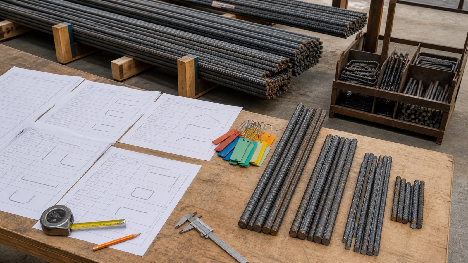
| Bar list | Quantity, size, length and fabrication identity | Matches placing information |
| Coupler submittal | Product, bar compatibility, preparation and installation record | Accepted system and revision |
| Field change record | Moved, added, removed or changed splice | Approved disposition |
Use the slab rebar measurement guide for grid limits and bar directions. The rebar cutting-list guide carries approved piece lengths into stock patterns.
Which fields belong in a splice ledger?
| Field | Example | Purpose |
|---|---|---|
| Element and release | Slab S1, R3 | Controls location and sequence |
| Bar mark | B12 | Connects drawing, list and tag |
| Designation and material | #5 / #16, as specified | Identifies the accepted bar and connection |
| Splice type | Lap or approved mechanical system | Sets the quantity method |
| Zone | Z1 or Z2 | Preserves staggering and restrictions |
| Junction count | 12 | Counts physical connections once |
| Approved lap | 0.800 m | Calculates added steel for lap rows |
| Coupler product | Accepted submittal reference | Connects count to a compatible assembly |
| Source | S-501 Rev 4, Detail 8 | Makes the entry auditable |
How is added lap length calculated?
Multiply the number of lap junctions by the approved overlap length. Keep installed run length and added overlap visible as separate quantities.
Added lap length = lap-splice count x approved lap length
Cut length with laps = installed run length + added lap length
A bar running through 2 lap junctions adds 2 approved overlaps. A bar that stops, anchors, hooks or uses another connection follows its approved fabrication mark.
How many stock pieces does one straight run need?
For a straight run with one stock length and one approved lap, each added piece advances by stock length minus lap.
Pieces per run = ceiling((run length - lap) / (stock length - lap))
Splices per run = pieces per run - 1
The formula applies only when the drawings permit those splice positions and every piece can use the entered stock and lap. Restricted zones, different end pieces, staggered junctions, hooks or couplers need a mark-by-mark schedule.
Worked example: 16 long runs with approved laps
Sixteen straight bar runs are each 28 m long. The confirmed stock length is 12 m, and the approved lap for these marks and locations is 0.75 m.
- Effective advance after the first piece: 12 - 0.75 = 11.25 m.
- Pieces per run: ceiling((28 - 0.75) / 11.25) = 3.
- Splices per run: 3 - 1 = 2.
- Total splice count: 16 x 2 = 32.
- Installed run length: 16 x 28 = 448 m.
- Added lap length: 32 x 0.75 = 24 m.
- Cut length with laps: 448 + 24 = 472 m.
The result describes straight cut length before stock-pattern, allowance or supplier rounding. The calculator does not approve the 0.75 m lap or its locations.
Does staggering change the splice count?
Staggering changes where junctions occur. It does not create another splice for the same bar unless the approved layout shows another physical junction.
Suppose 24 bars each receive one 0.8 m approved lap. The placing drawing splits them into 2 zones with 12 bars per zone:
| Zone | Bars spliced | Approved lap | Added length |
|---|---|---|---|
| Z1 | 12 | 0.8 m | 9.6 m |
| Z2 | 12 | 0.8 m | 9.6 m |
| Total | 24 | One lap per bar | 19.2 m |
Keep the zones separate in fabrication and placement records even though their quantity totals can be checked together.
How are mechanical couplers counted?
Count one approved coupler assembly for each mechanical-splice junction shown in the schedule. Separate counts by product, bar designation, grade, coating, end preparation, location and release.
In the 16-run example, replacing both approved lap junctions per run with mechanical splices gives 16 x 2 = 32 coupler junctions. The installed bar run remains 448 m in geometric length, and the takeoff adds no lap overlap. Approved cut ends and coupler engagement dimensions still control the fabrication lengths.
| Record | Lap splice | Mechanical splice |
|---|---|---|
| Connection count | One per approved overlap junction | One per approved coupler junction |
| Added bar length | Approved lap x junction count | Use approved cut and engagement details |
| Separate product | None unless the detail adds a splice bar or accessory | Coupler assembly and any specified accessories |
| Traceability | Bar marks, zone and lap source | Product, lot or tag record and bar compatibility |
How are separate splice bars recorded?
List a separate splice bar as its own mark, quantity and approved cut length. Do not add its full length to the continuing bars and also treat the same dimension as overlap on those bars.
Record the 2 interfaces or connection points if the project tracks them, while keeping one physical splice-bar piece in the material count. The detail decides whether the bar is straight, bent, coated or tied to a staged pour.
How should revisions and field changes be reconciled?
Preserve the issued splice baseline, then post each approved change against the affected marks and zones. A moved splice can change piece lengths and stock patterns even when the number of junctions stays constant.
| Change | Quantity effect | Record to update |
|---|---|---|
| Lap value changes | Added length and piece lengths | Lap source, bar list and cut plan |
| Splice moves | Piece lengths and stagger zone | Placing drawing and mark schedule |
| Lap changes to coupler | Removes overlap, adds compatible product count | Approved detail, submittal and fabrication list |
| Bar mark added or removed | Connection and material count | Release, bundle and delivery record |
| Field-installed correction | Project-specific pieces or connectors | Approved disposition and as-built record |
Which splice takeoff mistakes cause errors?
- Using a fixed diameter multiple without checking the approved project value.
- Adding one lap to a run that contains 2 junctions.
- Counting each stagger zone as another set of physical splices.
- Adding lap overlap to a mechanical-splice row.
- Counting one coupler for 2 separate junctions.
- Mixing couplers for different bar products or end preparations.
- Adding a separate splice bar twice.
- Moving a splice without revising the cut lengths.
- Using stock length to place a splice inside a restricted zone.
- Rounding every lap line before the group total.
What design, inspection and safety limits apply?
This takeoff cannot design a splice, calculate development, approve a lap class, select a coupler, authorize welding or accept a substitution. Structural drawings, specifications, approved placing information, product submittals and responsible professionals control those decisions.
FHWA's bridge checklist calls for checking splice locations against plans and verifying bar identity, length, bending and coating. Use the inspection and acceptance process that applies to the actual project.
OSHA 29 CFR 1926.701(b) requires guarding protruding reinforcing steel where a fall could cause impalement in covered U.S. work. Cutting, threading, pressing, welding, lifting and placement also require suitable equipment and site controls.
Use the Rebar Calculator after an approved rectangular grid and lap input are available. The Rebar Size and Weight Chart supports designation and unit-mass checks, and the Concrete Planning hub lists related resources.
Sources and source scope
- CRSI Splicing Bars: splice types, drawing responsibility and variables that change lap length.
- ACI PRC-315-18 public page: information needed for fabrication details, placing drawings and review.
- FHWA Bridge Deck Rebar Checklist: bundle, bar, placement and splice checks in its bridge-review scope.
- NIST Guide to the SI, Appendix B: exact length conversions.
- OSHA 29 CFR 1926.701: United States protruding-rebar impalement protection context.
Source scope: CRSI and ACI support splice and detailing context. FHWA supports its named bridge checklist, NIST supports conversions, and OSHA supports the stated U.S. workplace rule. Project documents, accepted products, fabrication records and responsible professionals govern the actual splice.
Review note: Saleem Sial owns the research and editorial record. Source checks, independent splice fixtures, editorial review, build validation, link crawl, schema review and rendered QA form the internal publication gate. Waseem Sial, External Reviewer and Engineer, is listed for ongoing external review; no completed review date is claimed.