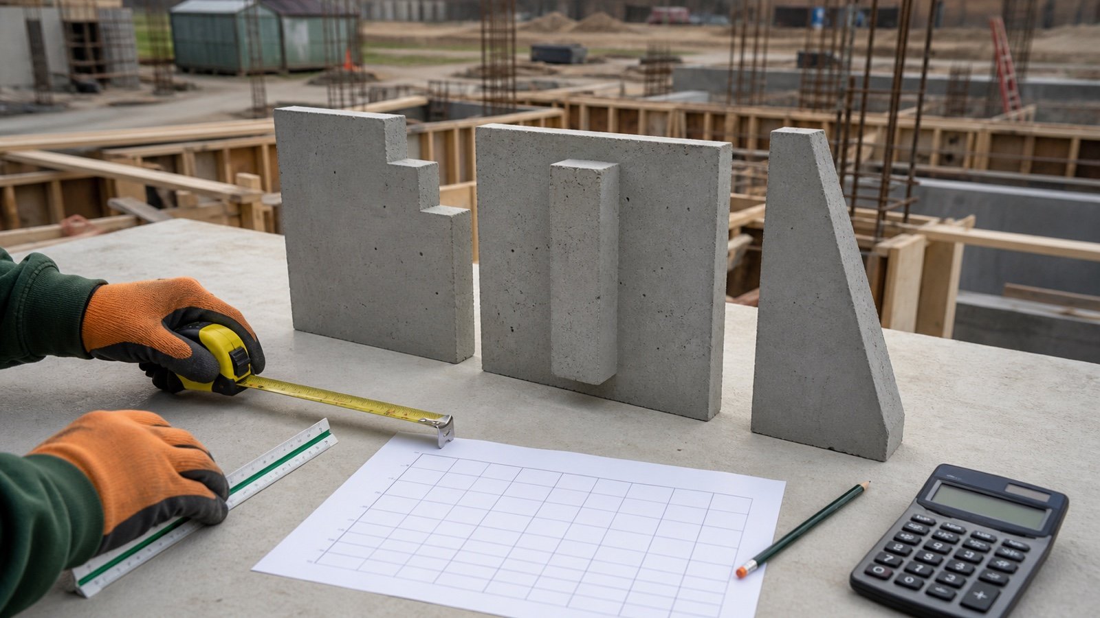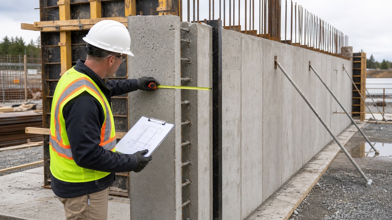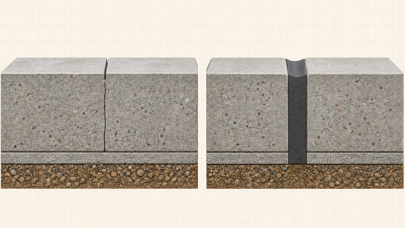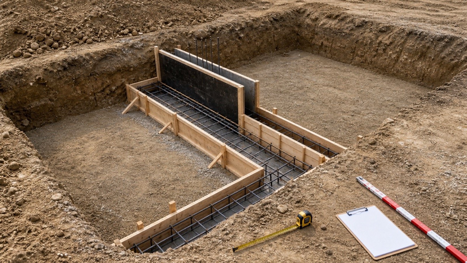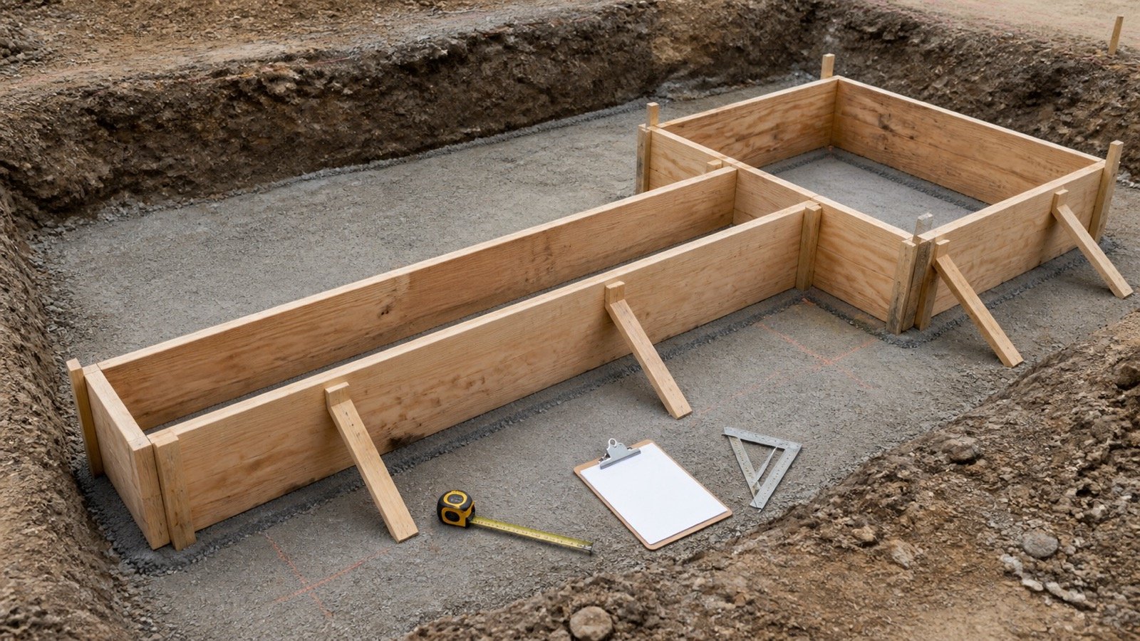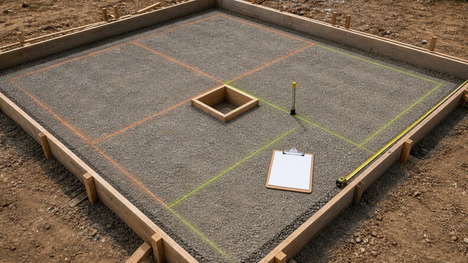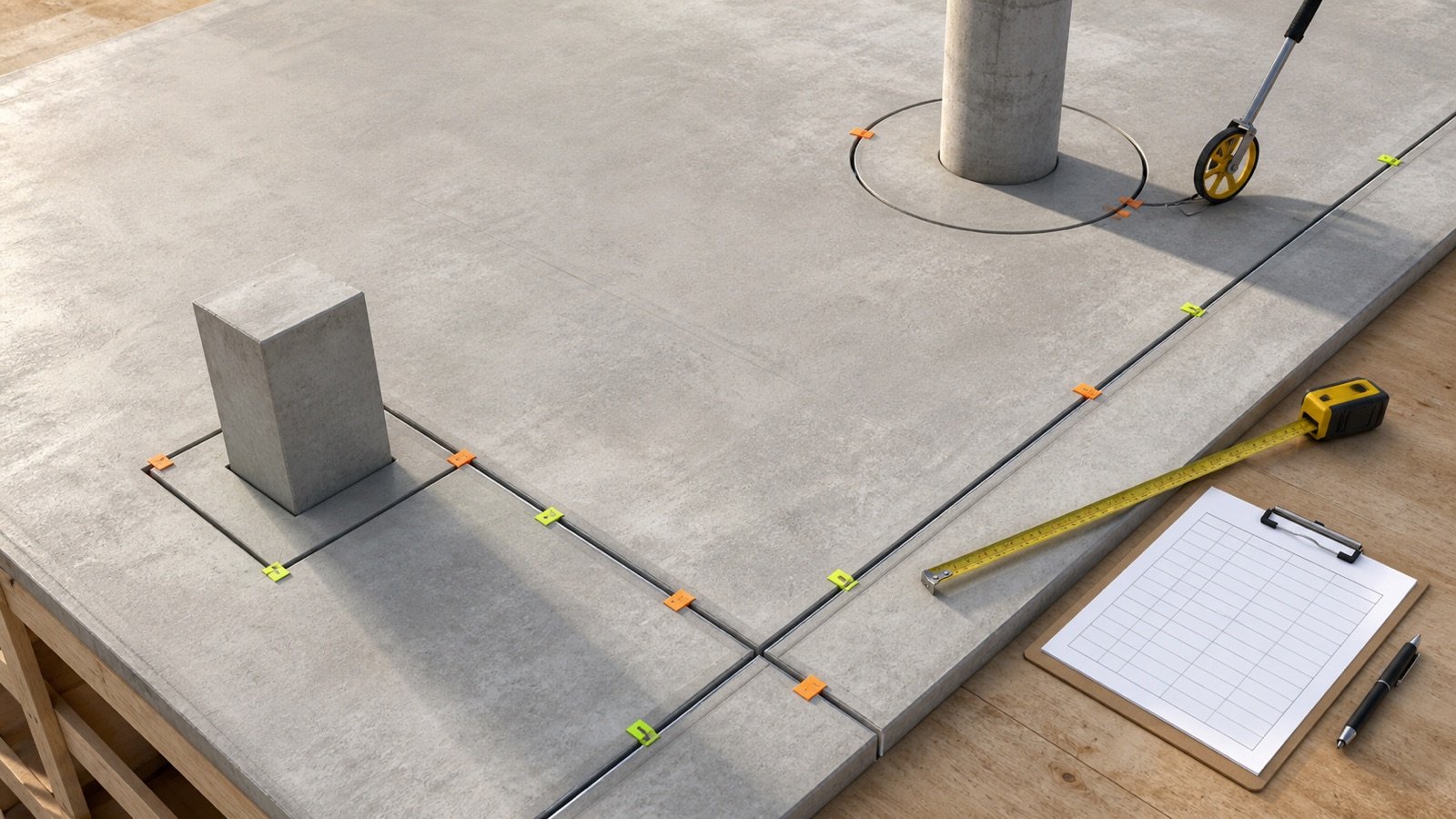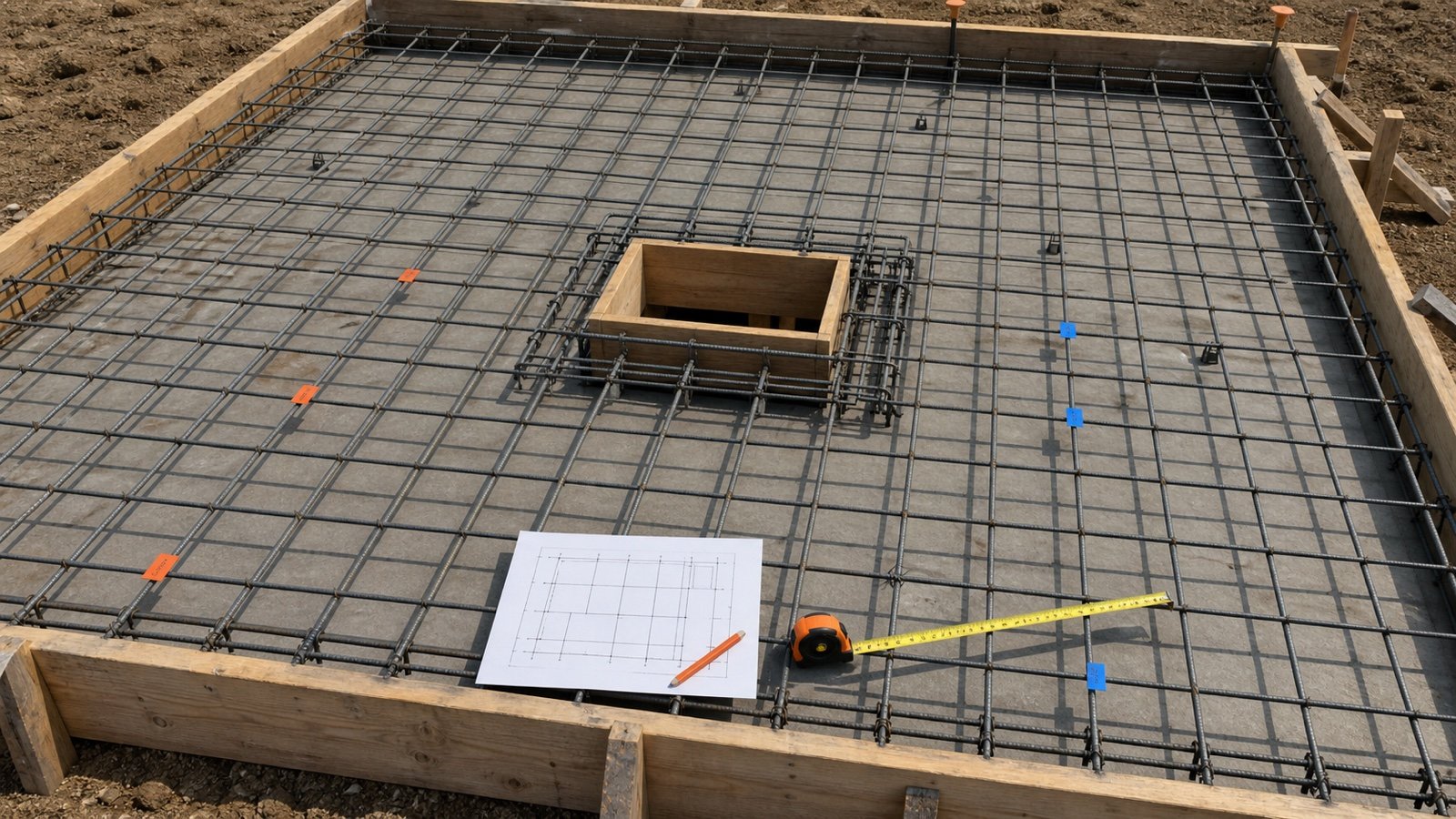
How do you calculate concrete for a haunched, stepped or tapered beam?
Mark every plane where the cross-section or quantity ownership changes. Calculate each constant prism, haunch, taper, opening, addition, or deduction once, then reconcile the sum with a simple rectangular baseline.
Use the Concrete Beam Calculator for constant rectangular zones. Use the methods below only when the drawing or accepted field record defines the transition geometry.
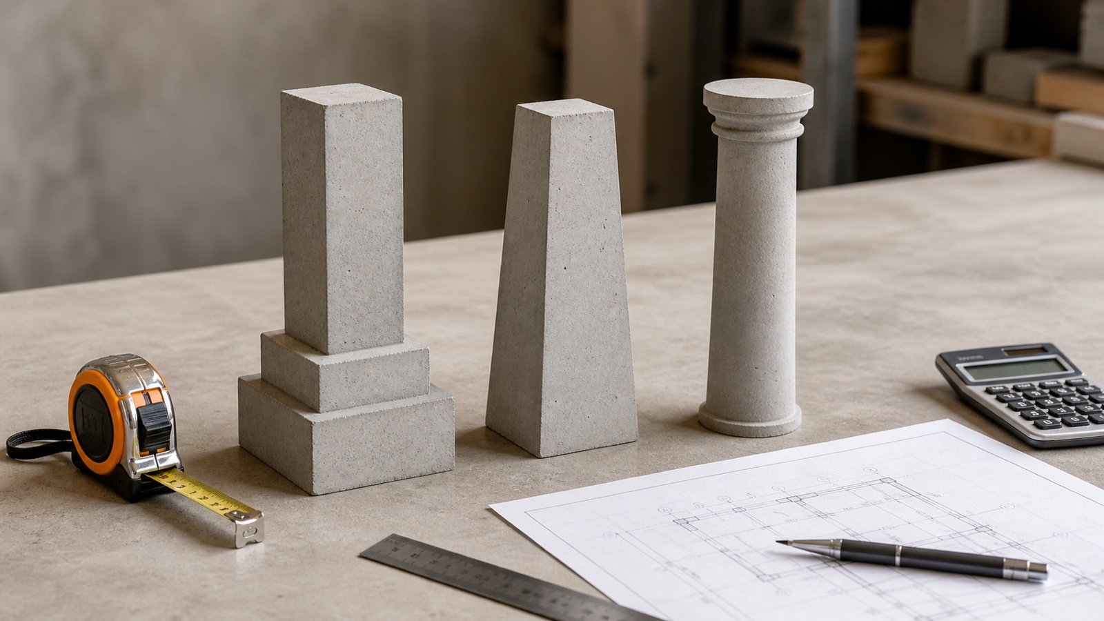
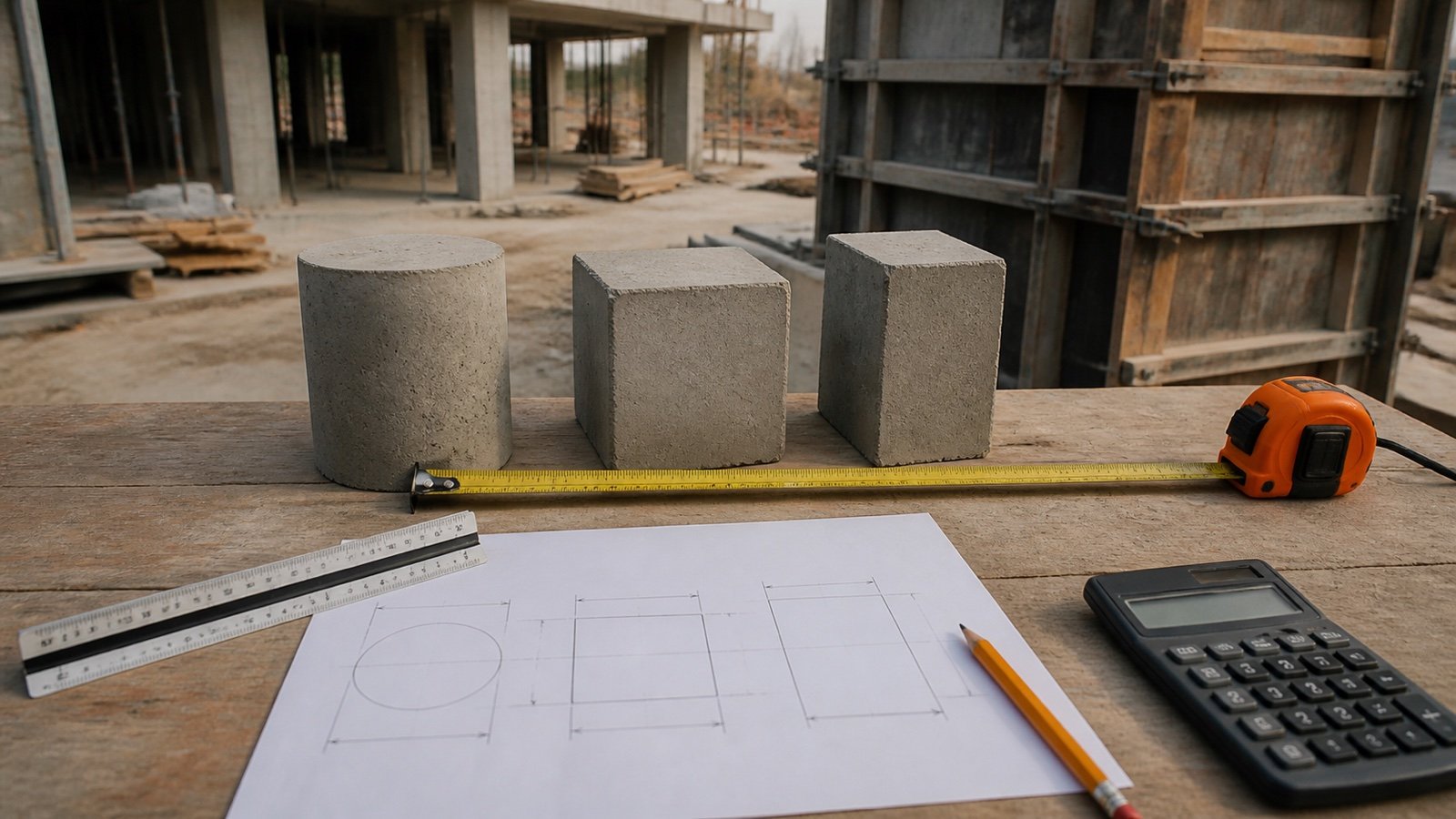
Equal end sections do not prove that the material between them is straight. A curved soffit, offset centreline, twisted face, stepped transition, and straight taper can contain different volumes.
Which method matches the beam geometry?
Choose the method from the actual boundary shown in sections and profiles. A beam name such as haunched or tapered does not define every intermediate section.
| Verified shape | Volume method | Required dimensions |
|---|---|---|
| Constant rectangular segment | Rectangular prism | True length, width and depth |
| Several constant depths or widths | Sum non-overlapping prisms | Start, end and section of every segment |
| Triangular haunch at constant width | Baseline prism plus triangular prism | Haunch length, added depth and width |
| One rectangular dimension changes linearly | Length x constant dimension x average changing dimension | Both end dimensions and true transition length |
| Width and depth both change linearly | Prismoidal formula | Start, midpoint and end areas plus true length |
| Curve, offset, twist or non-linear transition | Approved section integration or audited model | Sections at stated stations, axes and revision |
The FHWA field-formula manual gives prism and prismoidal relationships and warns against mixing units in one formula. It also says interim values should not be rounded. Those geometry rules support the calculations; they do not approve a beam shape or structural design.
Which records define the beam zones?
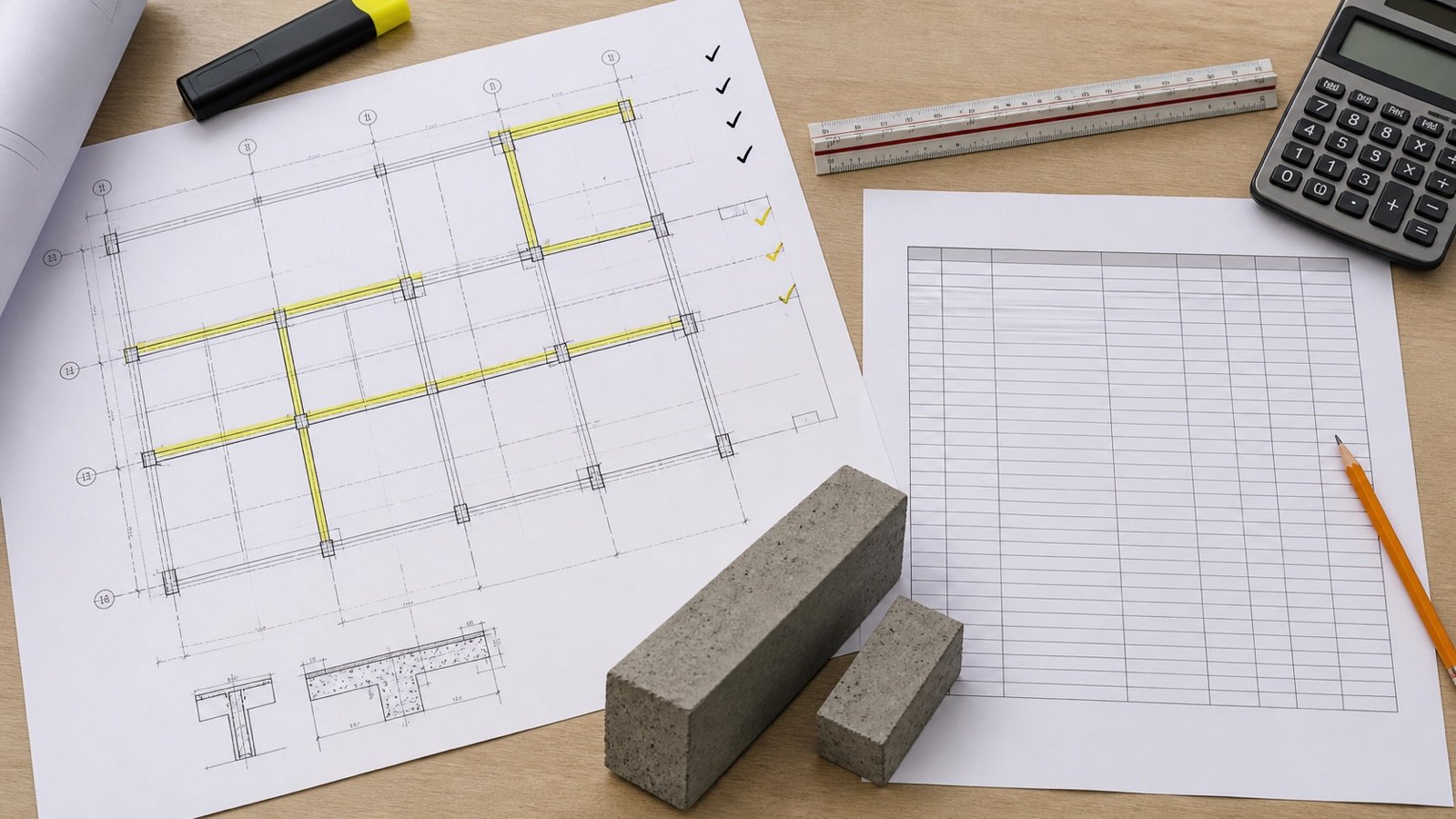
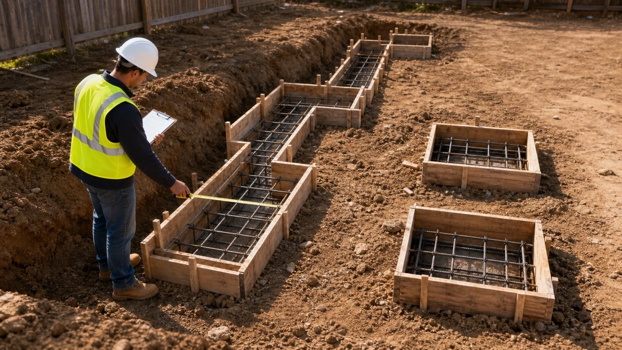
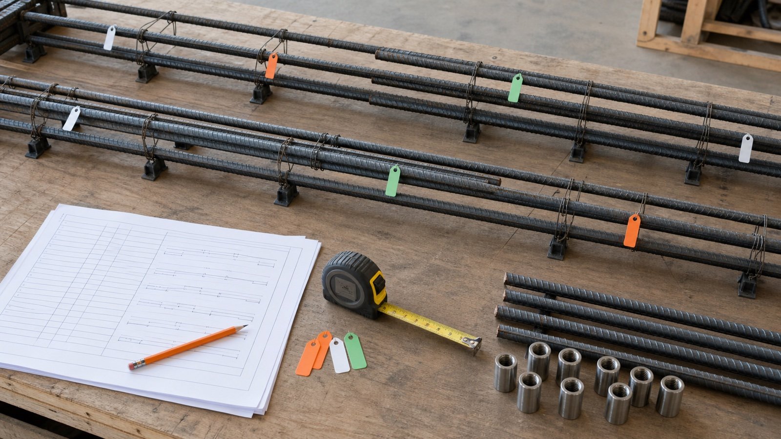
Use the current framing plan, beam schedule, longitudinal profile, cross-sections, support details, slab details, joint drawings, model revision, and adopted measurement rules. Record the beam mark and revision beside every row.
| Record | Check |
|---|---|
| Plan and beam schedule | Mark, count, supports, base width, overall depth and level |
| Longitudinal section | True transition length, step stations, soffit profile and slope |
| Cross-sections | Width, depth, voids, offsets and section orientation |
| Support and slab details | Shared concrete ownership and start or stop planes |
| Model record | Element IDs, joins, cuts, phase, units, revision and extraction date |
| Measurement rule | Net boundary, deductions, inclusions and reporting precision |
HKIS's quantity-information requirements recognize beam types including tapered, sloping, curved and cranked beams and list cross-sectional sizes, cut length and volume among the related data. The document provides a scoped workflow, so the project's own contract and records still control.
Prepare the beam marks, lengths and ownership boundaries with the Concrete Beam Quantity Takeoff before calculating special zones.
How do you calculate a stepped beam?
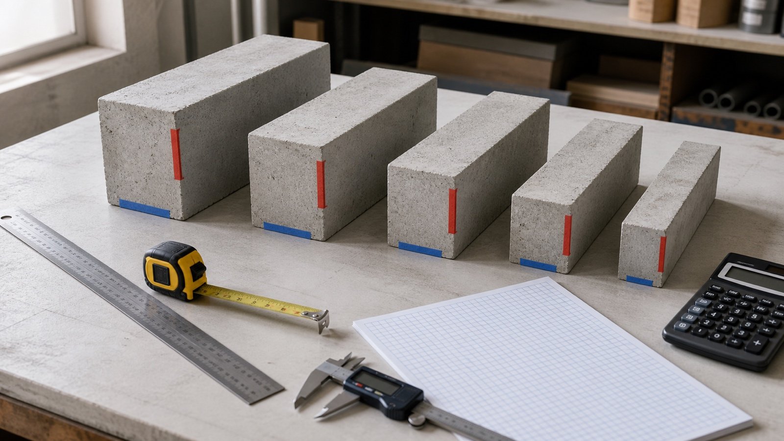
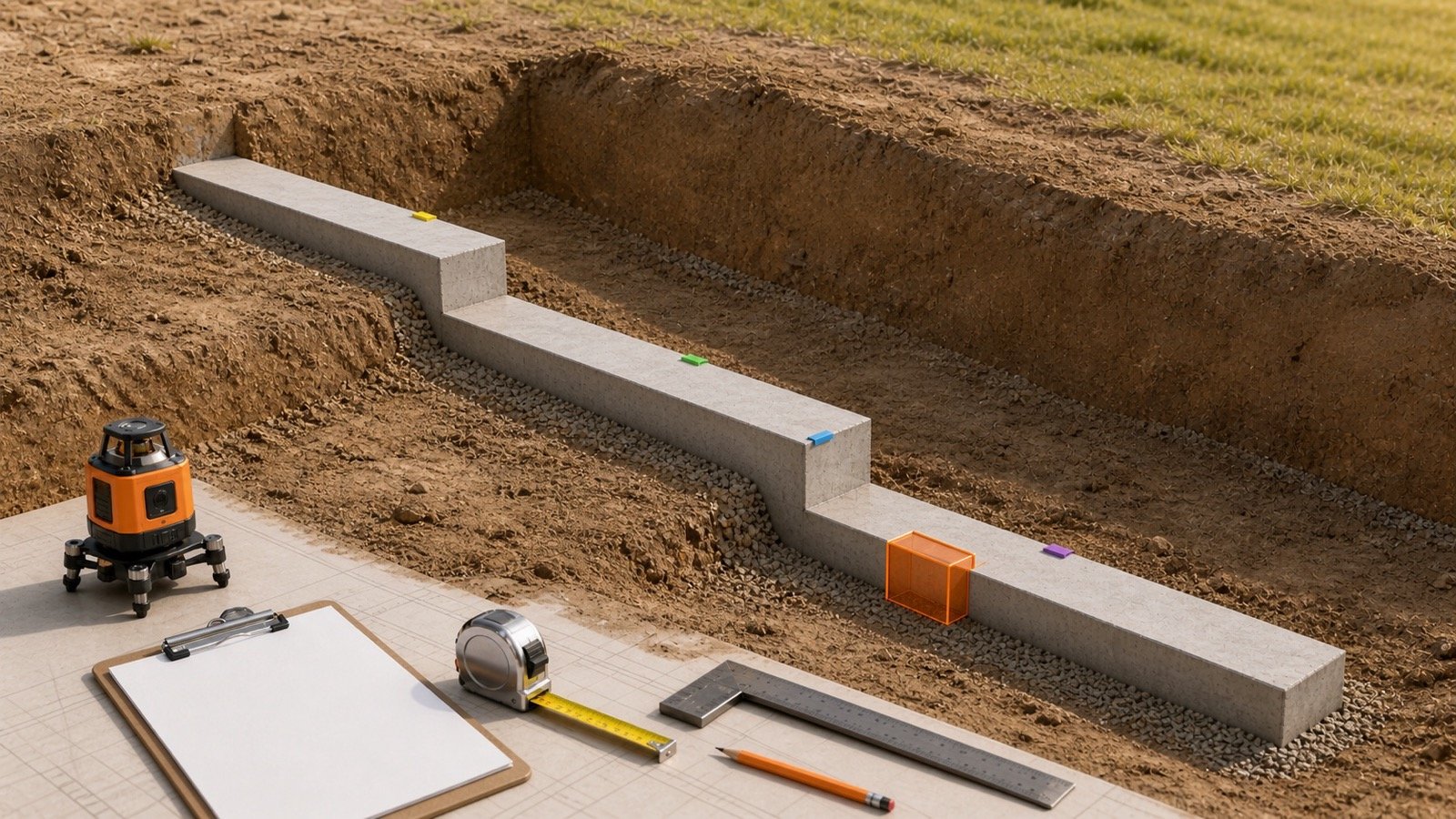
Split the beam at each abrupt section change and calculate every constant segment as length x width x depth. Adjacent segments meet at one plane and do not overlap.
Stepped beam volume = sum of each non-overlapping segment volume
Example: a 0.30 m wide beam is 0.60 m deep for 2.00 m and 0.45 m deep for the next 4.00 m.
| Zone | Calculation | Volume |
|---|---|---|
| Deeper segment | 2.00 x 0.30 x 0.60 | 0.360 m³ |
| Shallower segment | 4.00 x 0.30 x 0.45 | 0.540 m³ |
| Total | 0.360 + 0.540 | 0.900 m³ |
Using the 0.60 m depth over the full 6.00 m gives 1.080 m³. That is 0.180 m³ high because it invents a 0.15 m deep zone along the 4.00 m shallower segment.
How do you calculate a triangular beam haunch?
Calculate the constant baseline beam, then add the triangular haunch once. This method applies when the haunch has constant width, reaches a stated maximum added depth, and changes along a straight line to zero.
Triangular haunch addition = 1/2 x haunch length x maximum added depth x beam width
A 5.00 m beam is 0.30 m wide and 0.45 m deep. At one support, a 1.50 m long haunch adds 0.30 m of depth at the support and tapers linearly to zero.
- Baseline volume: 5.00 x 0.30 x 0.45 = 0.6750 m³.
- Haunch side-profile area: 1/2 x 1.50 x 0.30 = 0.2250 m².
- Haunch addition: 0.2250 x 0.30 = 0.0675 m³.
- Combined volume: 0.6750 + 0.0675 = 0.7425 m³.
A rectangular 0.30 m addition over the whole 1.50 m would add 0.1350 m³, exactly twice this straight triangular haunch. Use a trapezoid when the added depth does not reduce to zero.
How do you calculate a constant-width depth taper?
Average the 2 end depths when width stays constant and depth changes linearly over the true transition length. Cross-section area then changes linearly, so end-area averaging is exact.
V = L x b x (d1 + d2) / 2
Example: length 3.00 m, constant width 0.25 m, start depth 0.60 m and end depth 0.30 m.
V = 3.00 x 0.25 x (0.60 + 0.30) / 2 = 0.3375 m³.
The same relationship works when depth stays constant and width changes linearly. It does not automatically extend to a transition where width and depth both change.
What changes when beam width and depth both taper?
Use the prismoidal formula when both rectangular dimensions change linearly along the same straight axis. Calculate the actual midpoint area instead of averaging only the end areas.
V = L / 6 x (A1 + 4Am + A2)
A 3.00 m transition changes from 0.20 m x 0.30 m to 0.40 m x 0.60 m. Both width and depth vary linearly, so the midpoint is 0.30 m x 0.45 m.
| Section | Calculation | Area |
|---|---|---|
| Start | 0.20 x 0.30 | 0.060 m² |
| Midpoint | 0.30 x 0.45 | 0.135 m² |
| End | 0.40 x 0.60 | 0.240 m² |
Prismoidal volume = 3.00 / 6 x (0.060 + 4 x 0.135 + 0.240) = 0.420 m³.
Why does averaging only the end areas fail here?
End-area averaging gives 3.00 x (0.060 + 0.240) / 2 = 0.450 m³. It is 0.030 m³, or 7.14%, above the verified 0.420 m³ result because multiplying 2 linearly changing dimensions makes section area change quadratically.
| Transition | Endpoint average | Required check |
|---|---|---|
| Width constant, depth linear | Exact | Confirm straight change and true length |
| Depth constant, width linear | Exact | Confirm straight change and true length |
| Width and depth both linear | Can be wrong | Use start, midpoint and end areas |
| Curve, twist or offset | Unsupported | Use approved sections or audited model geometry |
If a measured midpoint differs from the midpoint implied by the end dimensions, the profile is not the assumed straight double taper. Stop and obtain the actual section sequence.
Which length should a sloping or cranked beam use?
Use the true length along the axis that is perpendicular to the recorded cross-sections. A horizontal plan projection can understate a sloping segment.
For a straight segment with horizontal run R and vertical rise H, the true centreline length is the square root of R² + H² when the project records define those legs and the sections remain perpendicular to that axis. A crank needs separate straight segments and transition details. Do not bridge a bend with one chord unless the accepted geometry calls for it.
Keep support intersection ownership consistent. A true sloping length does not authorize extending the beam volume through a column, wall, or slab zone already measured elsewhere.
How should curved, offset or twisted beams be measured?
Use approved cross-sections at stated stations or an audited model when a simple solid does not match the geometry. Record how the volume between sections was interpolated.
- Mark stations at ends, changes in curvature, steps, supports, openings and joints.
- Measure sections perpendicular to the adopted beam axis.
- Record whether the centreline and section centroids move or rotate.
- Calculate between stations with a method valid for the verified profile.
- Refine the station spacing until further refinement changes the result by less than the project's accepted tolerance.
- Retain the section set, formula, model revision and checker record.
A model volume needs category, phase, design option, joins, cuts, voids, units, element IDs and extraction date. Compare one representative model member with a manual fixture. USACE estimating guidance emphasizes traceable assumptions and reproducible quantities; a screenshot of one total does not meet that test.
How do slab, column and wall intersections affect the total?
Assign every shared zone once. A full-depth beam can overlap a continuous slab quantity, while a beam extended through supports can overlap column or wall quantities.
| Shared zone | Possible recorded rule | Required paired action |
|---|---|---|
| Beam within slab thickness | Beam owns full depth | Stop or deduct slab volume at the beam zone |
| Beam within slab thickness | Slab owns overlap | Measure only the beam drop below or above the slab |
| Beam at column or wall | Support owns intersection | Stop beam at the accepted support plane |
| Construction joint or stop end | Quantity follows pour boundary | Start the next zone at the same plane |
RICS NRM 2 provides one UK detailed-measurement framework for net in-situ concrete quantities and beam member information. Other contracts can use different ownership rules. State the adopted method and apply it across the Concrete Slab Calculator, beam schedule, and support quantities.
How do openings, rebates and embedded items change the quantity?
Calculate a verified geometric deduction separately, then apply the project's measurement rule. Do not change the scheduled beam width or depth to hide a local void.
Record the opening mark, shape, clear dimensions, location, intersected beam zone and quantity treatment. Small reinforcement, ducts, inserts and embedded components can have specific inclusion rules under an adopted standard. The component's physical volume alone does not decide the bill treatment.
How should the measured volume move into an order?
Complete and reconcile the net geometry first. Add only compatible beam zones, then apply a documented allowance and supplier rounding as separate steps.
- Total unrounded net volumes by beam mark, concrete mixture, pour and phase.
- Keep disputed geometry and pending revisions outside the approved subtotal.
- Apply the project allowance and record its reason and approval source.
- Use the Ready-Mix Concrete Calculator for delivery planning or the Concrete Bags Calculator with the exact product's current mixed yield.
- Confirm current supplier selling increment, minimum load, access, pump, placement, testing, waiting-time and return terms.
Geometry does not supply a universal allowance, density, bag yield, truck capacity or price. Keep those project and supplier inputs visible outside the measured volume.
Which mistakes change an irregular beam quantity?
- Extending the deepest section through the full beam length.
- Adding a haunch on top of a baseline that already includes the haunch zone.
- Measuring a triangular haunch as a full rectangular addition.
- Averaging only end areas when width and depth both change.
- Assuming straight sides from 2 end sections when the profile is curved.
- Using horizontal projection as the length of a sloping segment.
- Bridging a cranked or curved centreline with one chord.
- Counting slab, column or wall intersections twice.
- Using outside form dimensions instead of clear concrete boundaries.
- Mixing millimetres with metres or inches with feet.
- Rounding each small zone before summing the member.
- Accepting a model total without filters, joins, revision and a manual check.
- Hiding allowance inside the shape dimensions.
- Treating quantity geometry as structural approval.
What design and construction limits apply?
These methods calculate geometric volume. They do not size a haunch, approve a taper, check strength, shear, deflection, cracking, reinforcement, anchorage, concrete properties, form pressure, shores, braces, placement sequence, curing, stripping or construction loading.
Use current structural drawings, specifications, approved shop and formwork drawings, project safety controls, inspection requirements and governing codes. Send missing dimensions, conflicting profiles, uncertain boundaries and model discrepancies to the responsible project team before ordering.
Use the Concrete Beam Formwork Area guide for contact faces. A sloping or tapered concrete volume does not directly provide plywood, panels, ties, shores, braces, reinforcement or labour.
Final irregular-beam quantity check
- Freeze the current drawing and model revisions.
- List each beam mark, count, zone, boundary and unit.
- Match each zone to a valid prism, triangle, linear taper, prismoid or approved section method.
- Calculate additions and deductions once with full precision.
- Compare double tapers with a midpoint section.
- Reconcile beam, slab, column and wall ownership.
- Compare one model element with an independent manual fixture.
- Separate measured volume, allowance, supplier rounding, formwork and reinforcement.
- Record preparer, checker, assumptions, unresolved items and issue date.
Return to the concrete planning hub for related tools. The calculation methodology explains units, precision and rounding, and the corrections route accepts a source or arithmetic issue.
Sources and source scope
- FHWA Field Formulas M 22-24 supports the geometry formulas, unit discipline and final-stage rounding.
- HKIS BIM Measurement Information Requirements supports the stated beam types and quantity-information fields.
- RICS NRM 2 supports the stated UK detailed-measurement context.
- NIST Handbook 44 (2026), Appendix C supports the unit relationships.
- USACE Japan Engineer District Cost Estimating Guidance supports the traceability and reproducibility context.
Source scope: FHWA and NIST support geometry, calculation and units. HKIS and RICS support scoped quantity-information and measurement contexts. USACE supports estimating records. These sources do not select a beam shape, structural design, concrete mixture, boundary rule, allowance, formwork system, reinforcement or supplier order for a project.
Review note: Saleem Sial owns the research and editorial record. Formula fixtures, source checks, build validation and rendered QA form the internal publication gate. Waseem Sial, External Reviewer and Engineer, is listed for ongoing external review; no completed review date is claimed.