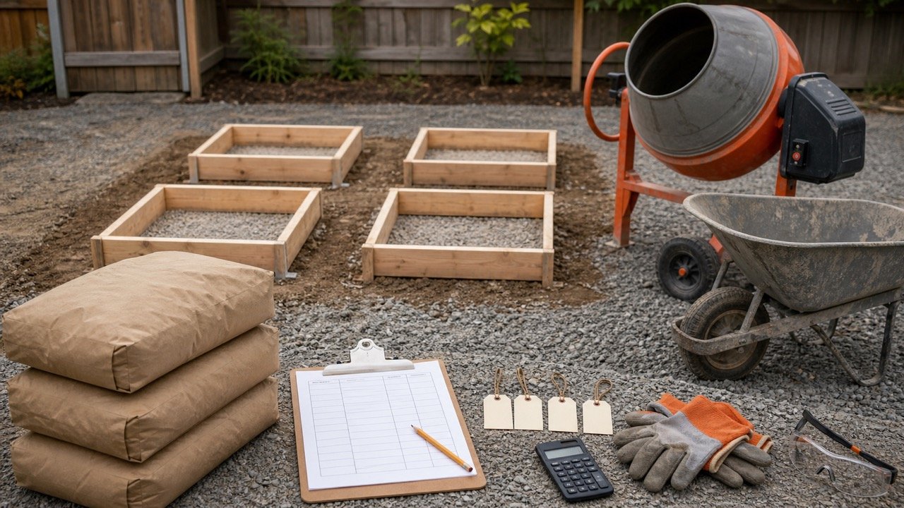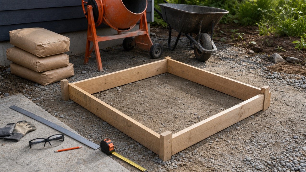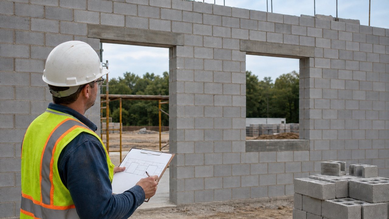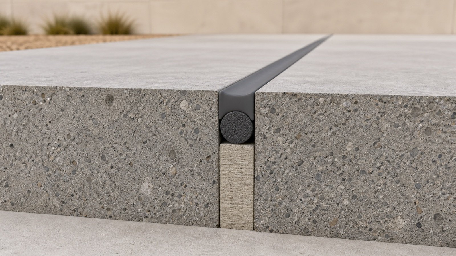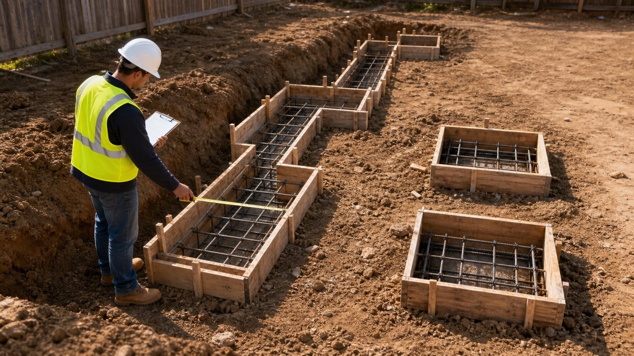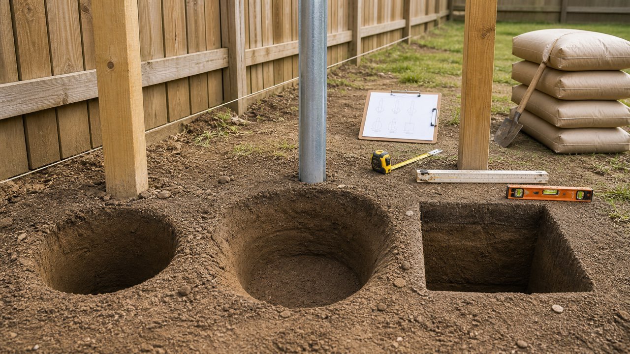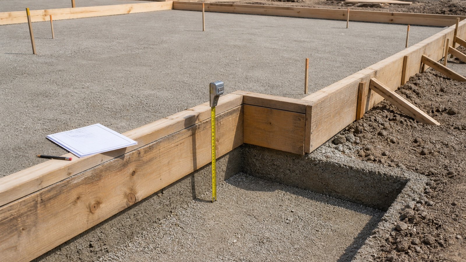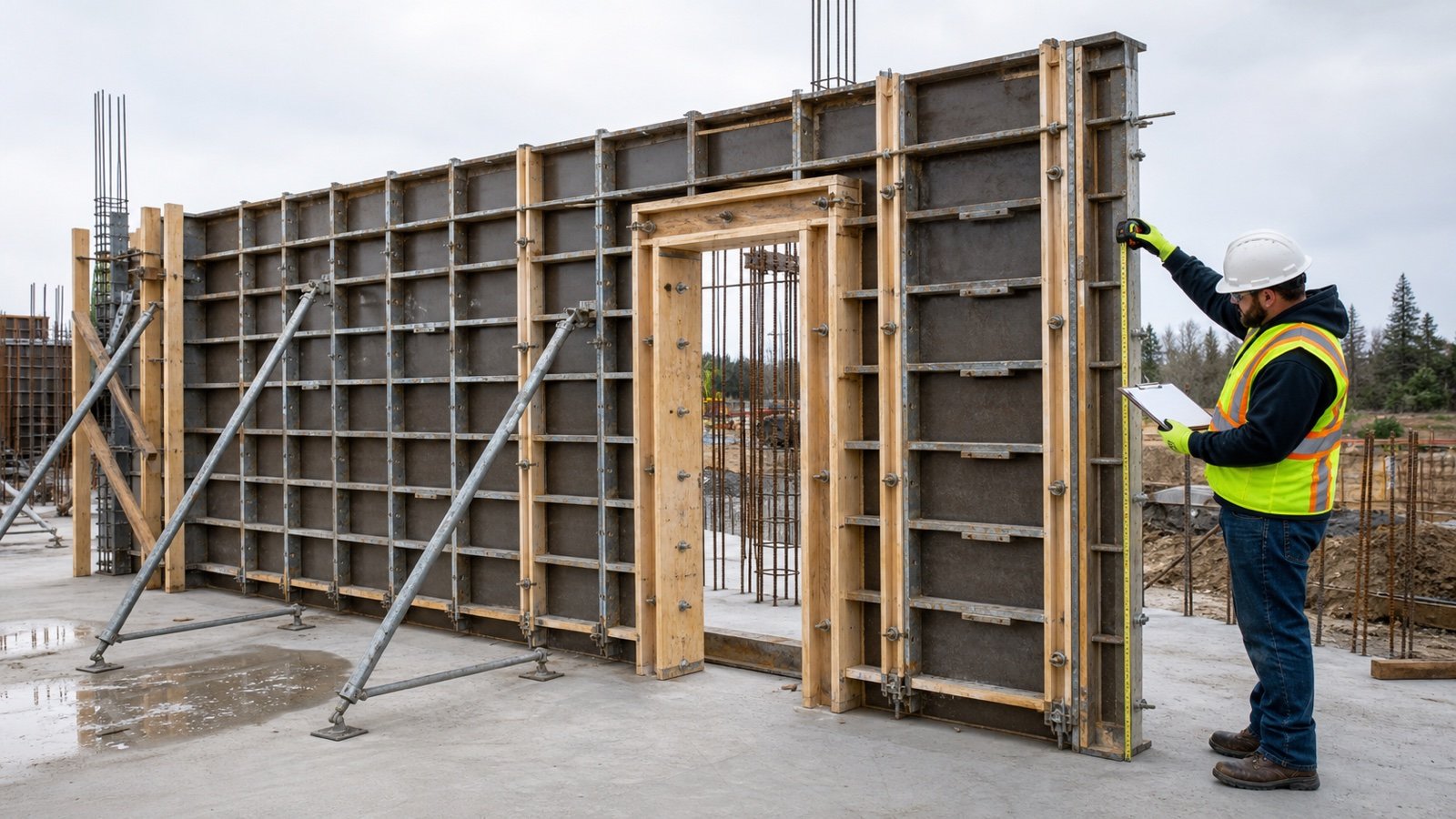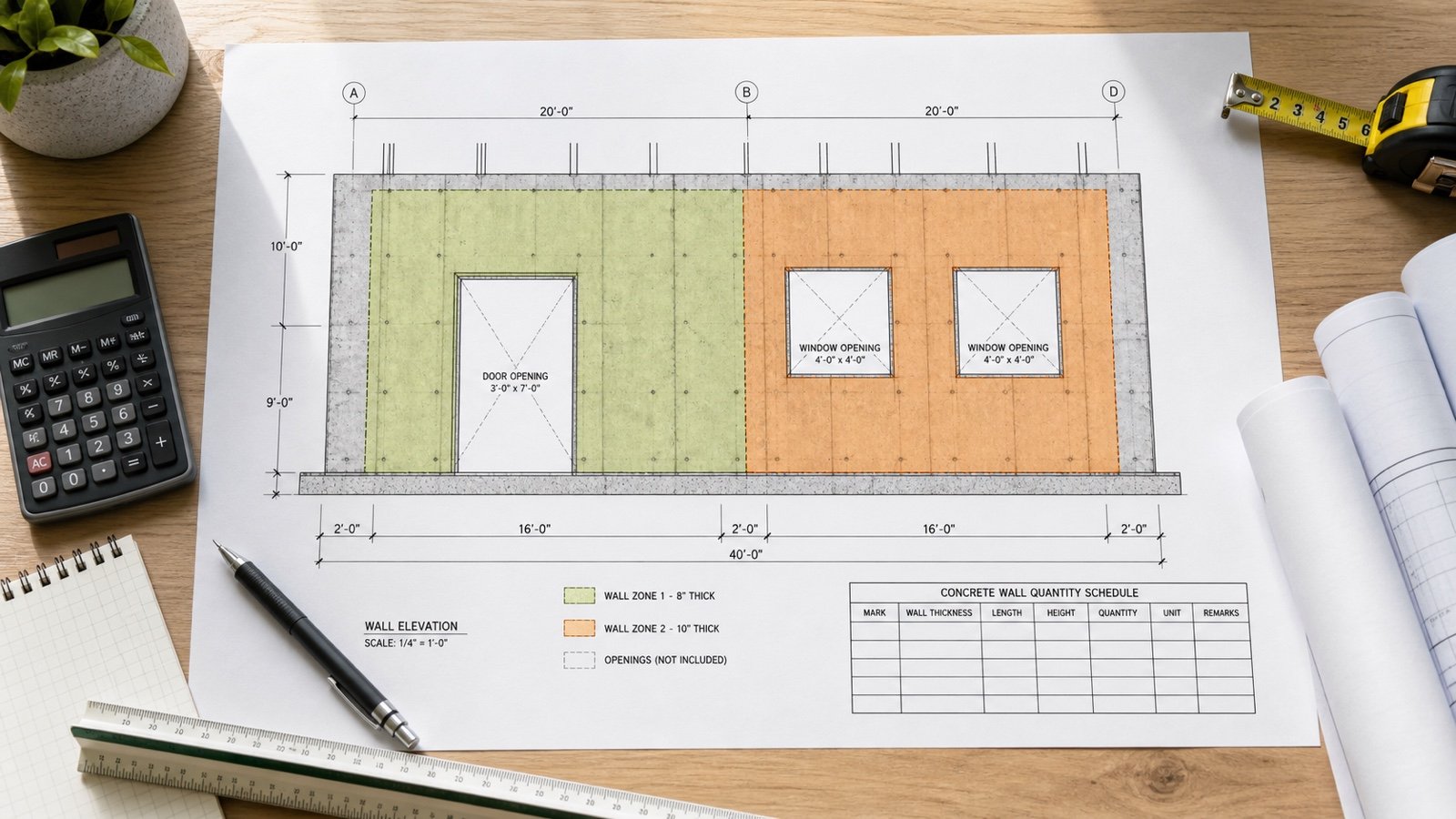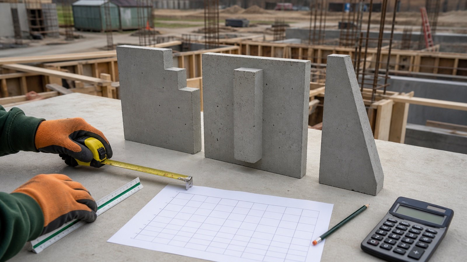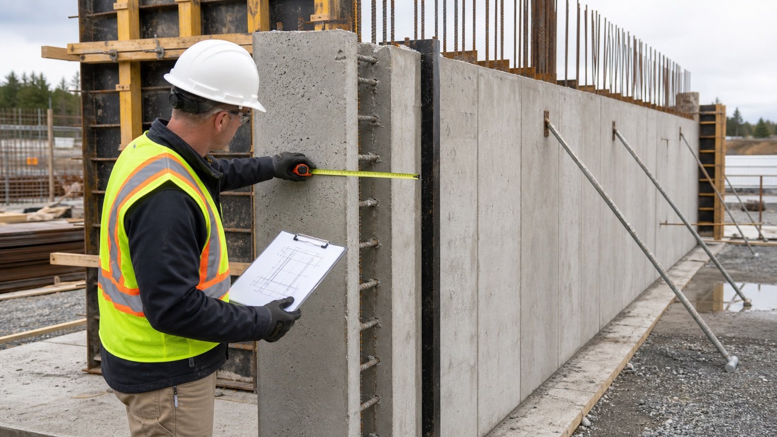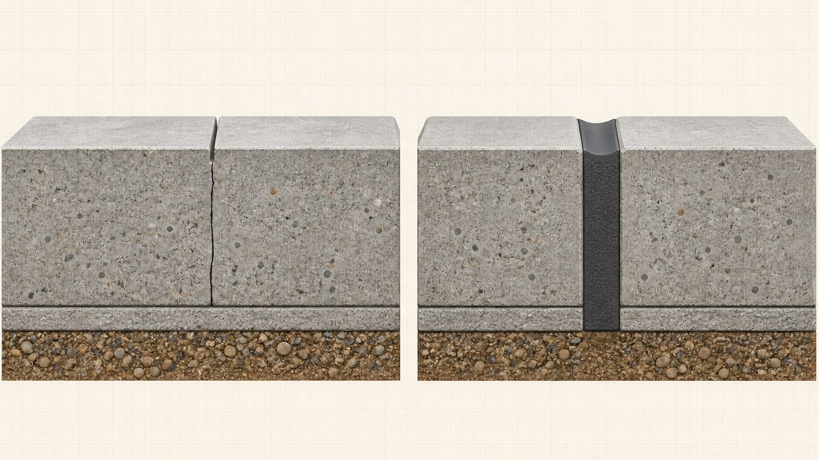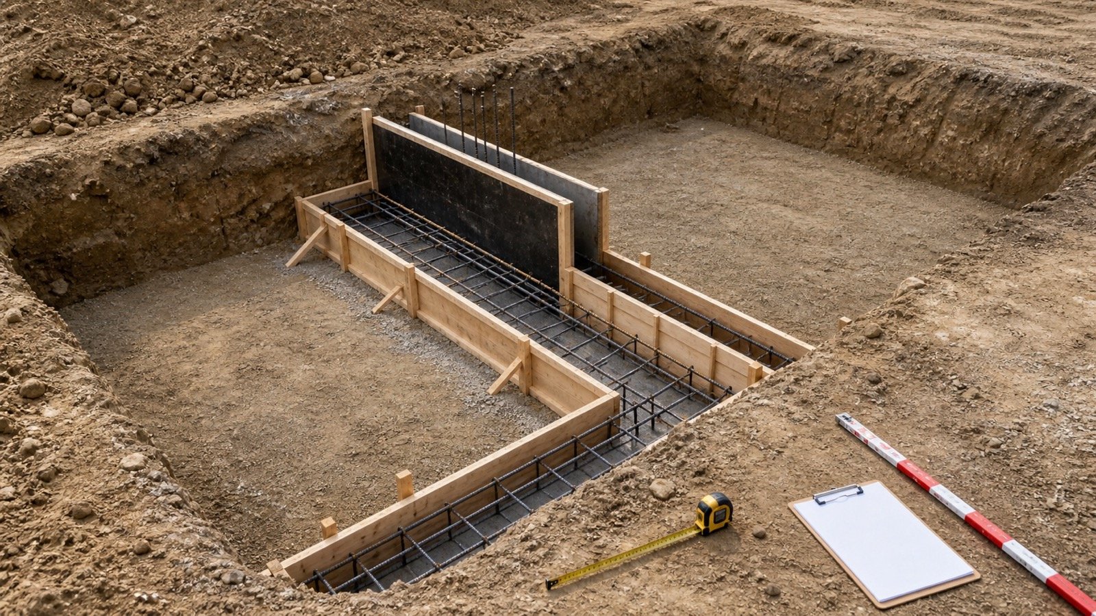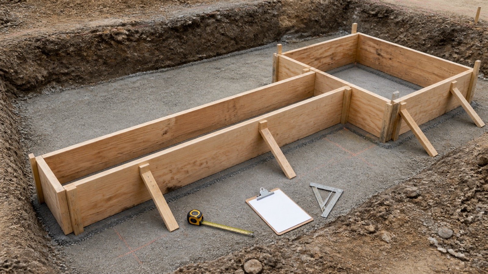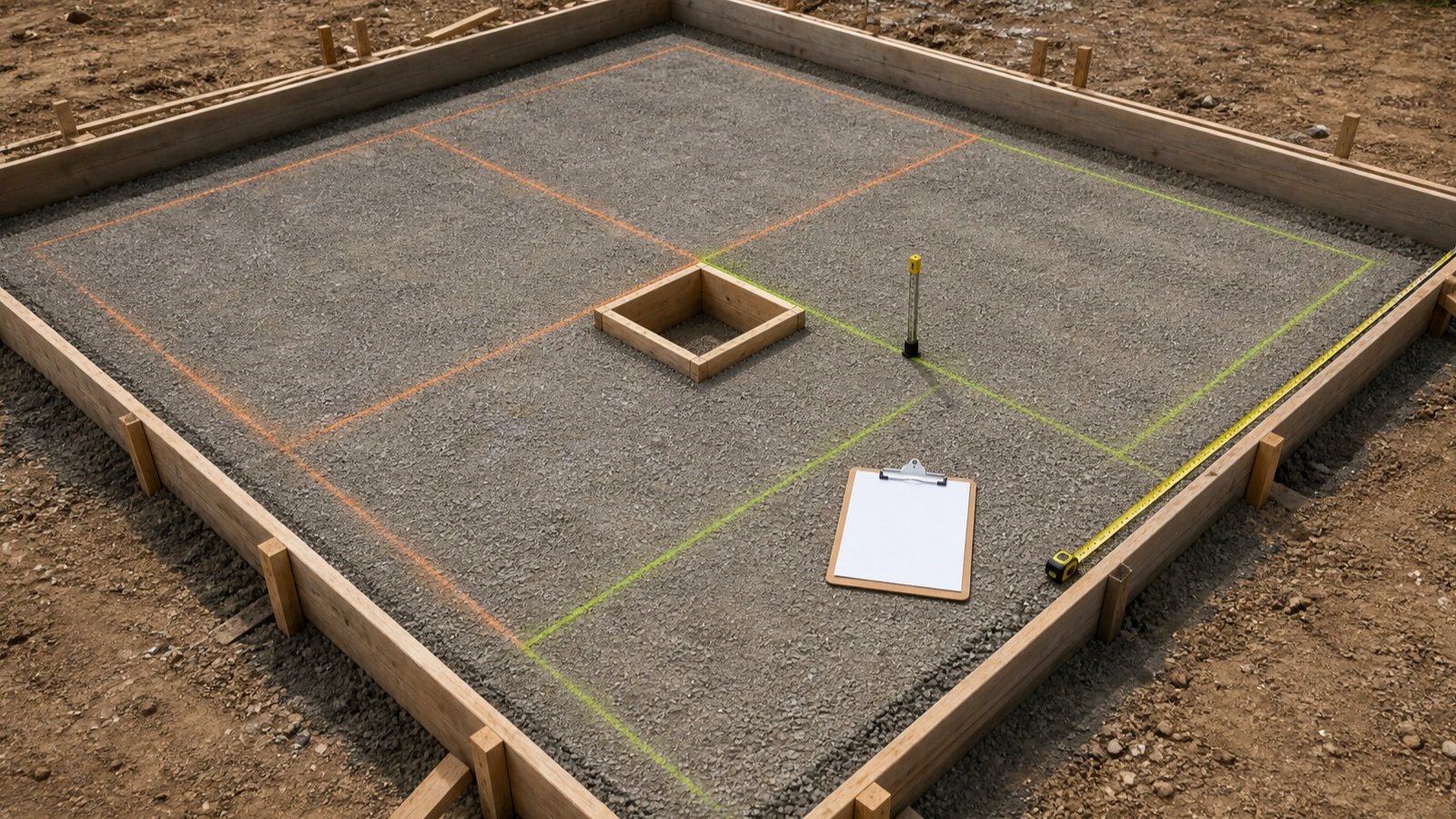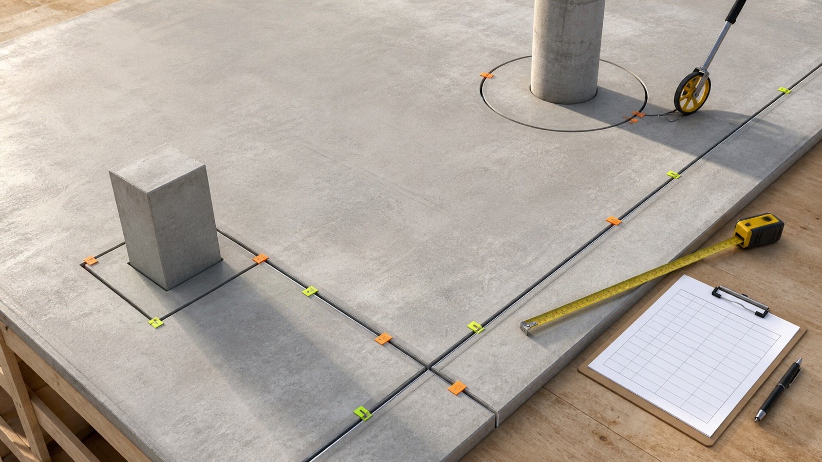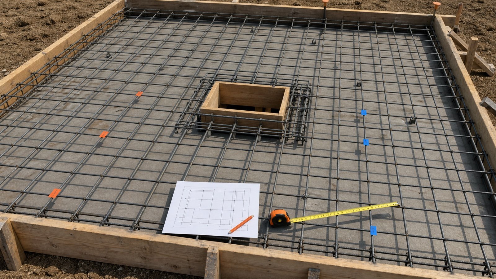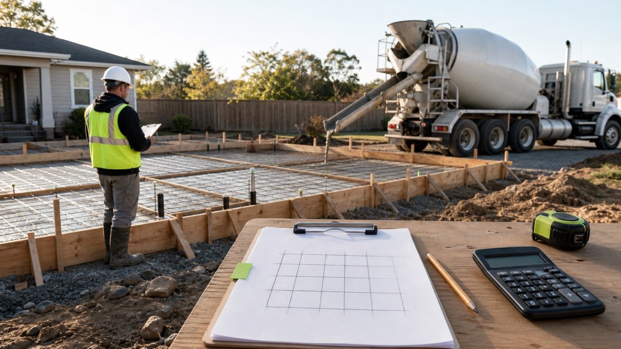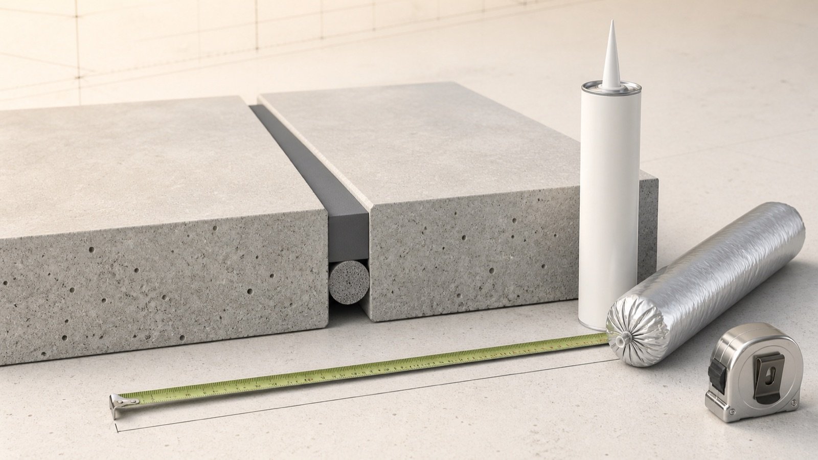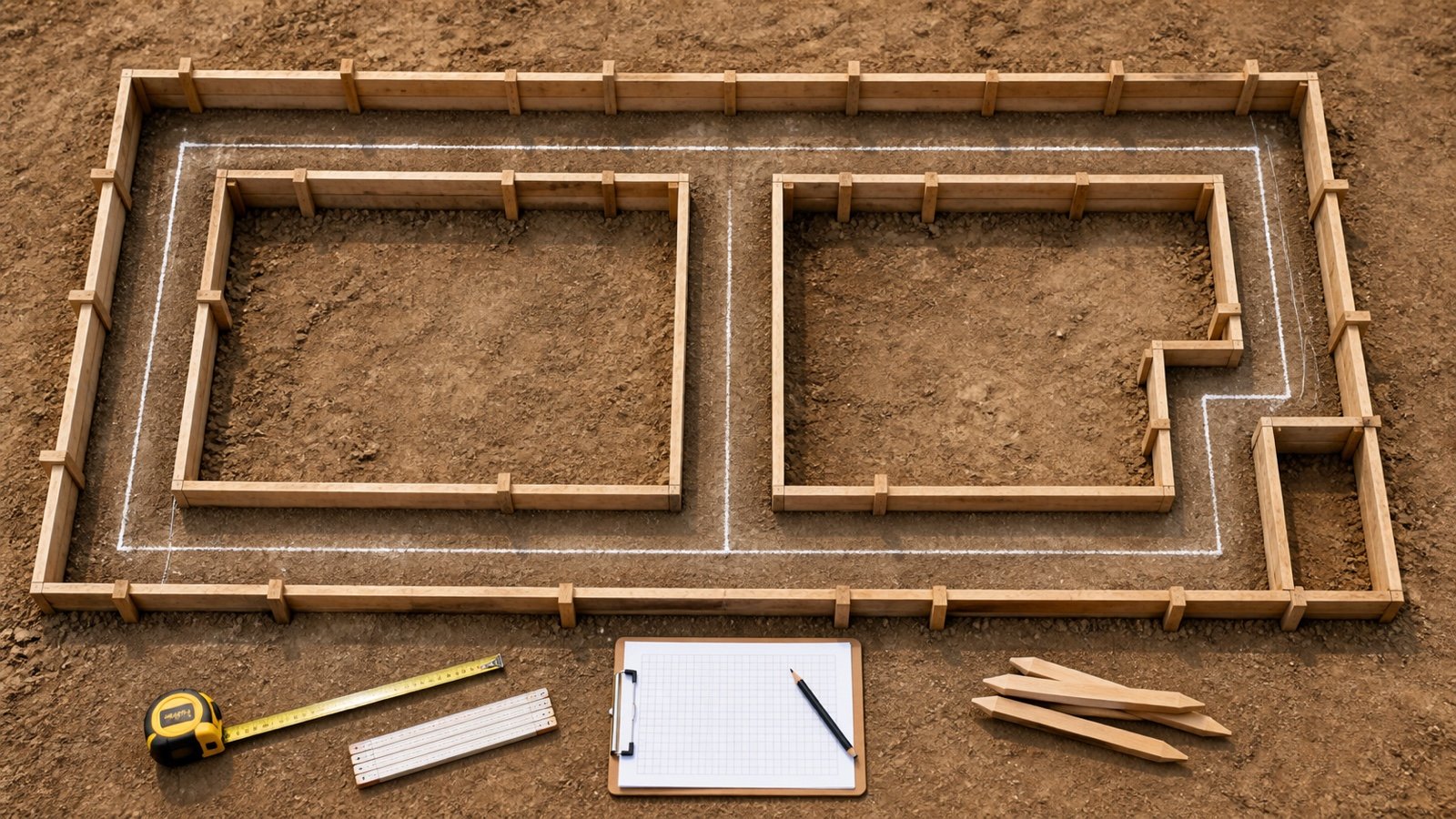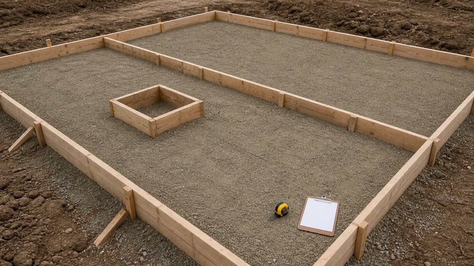
A rectangular 8 m by 5 m slab has a 26 m outside perimeter. If 150 mm of every outside edge touches a form, the outside contact area is 26 × 0.150 = 3.900 m².
That first line covers only the outside edge. Internal blockouts, pour stop ends, changing edge heights and a formed soffit need their own rows when they occur.
How do you calculate concrete slab formwork area?
Measure each concrete-face run that will touch a form, multiply its length by its formed contact height, and add the row areas. Add a slab soffit only when a form or temporary deck supports that underside.
Form-contact area = sum of (formed run × formed height × formed faces) + net formed soffit area
Record linear form run in metres or feet, contact area in square metres or square feet, and concrete volume in cubic metres or cubic yards.
Which slab surfaces count as formwork?
Count a surface when fresh concrete will touch a temporary form at that location. Project drawings, placement phases and the selected construction method identify those surfaces.
| Surface | Typical geometry record | Check before counting |
|---|---|---|
| Outside slab-on-ground edge | Concrete-face perimeter × formed height | The complete edge is retained by a form |
| Internal blockout face | Blockout perimeter × formed depth | The blockout uses temporary forms and remains open during the pour |
| Construction stop end | Stop length × retained concrete height | The row belongs to the correct placement phase |
| Suspended slab soffit | Verified net plan area of the formed underside | The permanent deck, opening and edge rules are recorded |
| Opening side face | Opening perimeter × formed slab depth | The opening passes through the slab and receives a form |
| Thickened edge or local drop | Each temporary contact face from its actual section | Ground, insulation or a permanent component may form another boundary |
| Concrete cast against accepted ground or permanent deck | Recorded outside the temporary form-contact total | Project measurement rules can still require a separate permanent-form or interface quantity |
OSHA defines formwork for covered U.S. work as the complete support system for fresh or partly cured concrete. Its definition includes the contact mold or sheeting and the supporting shores, reshores, hardware and braces. This article measures contact geometry only.
Which measurements belong in the takeoff?
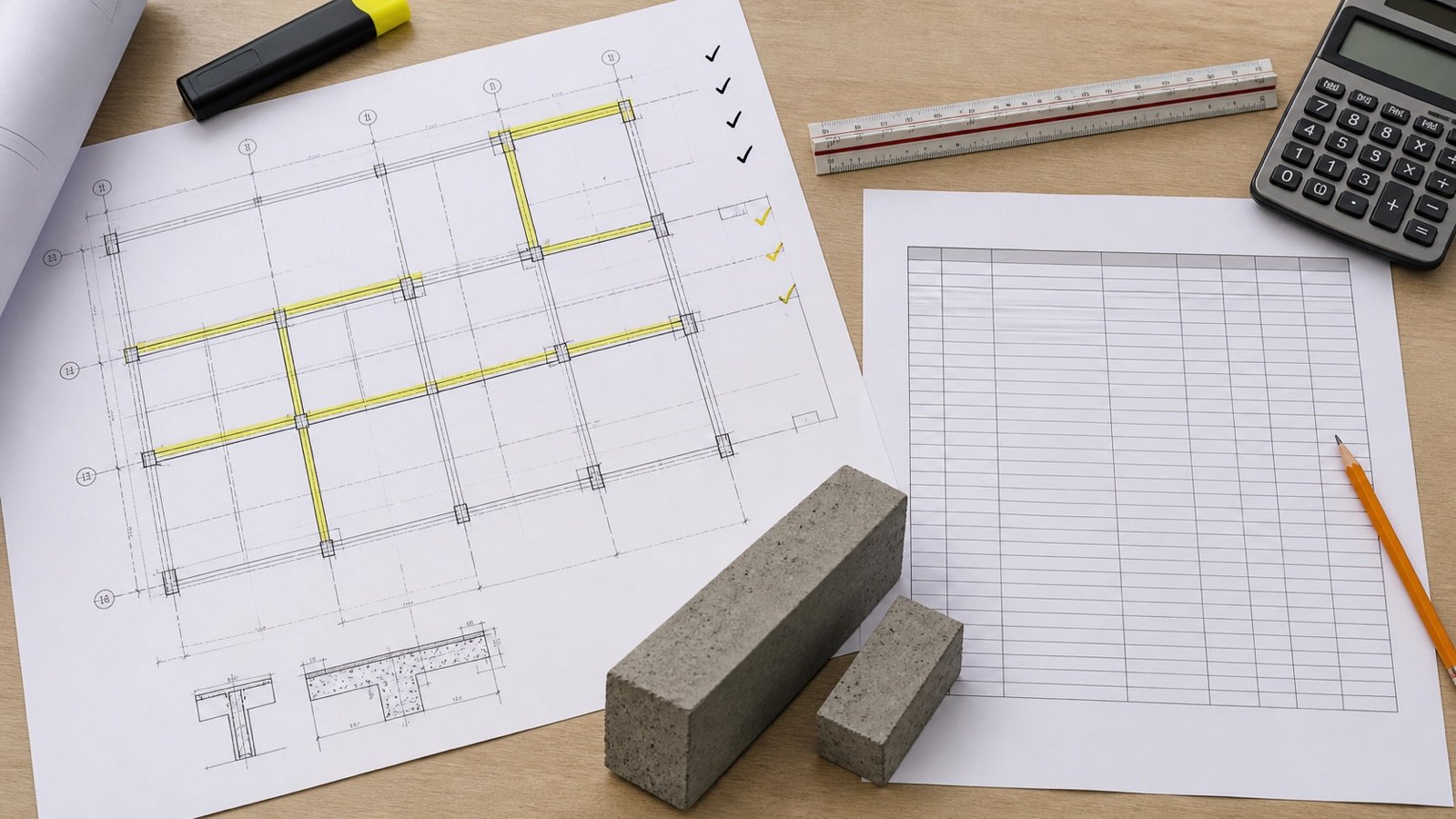
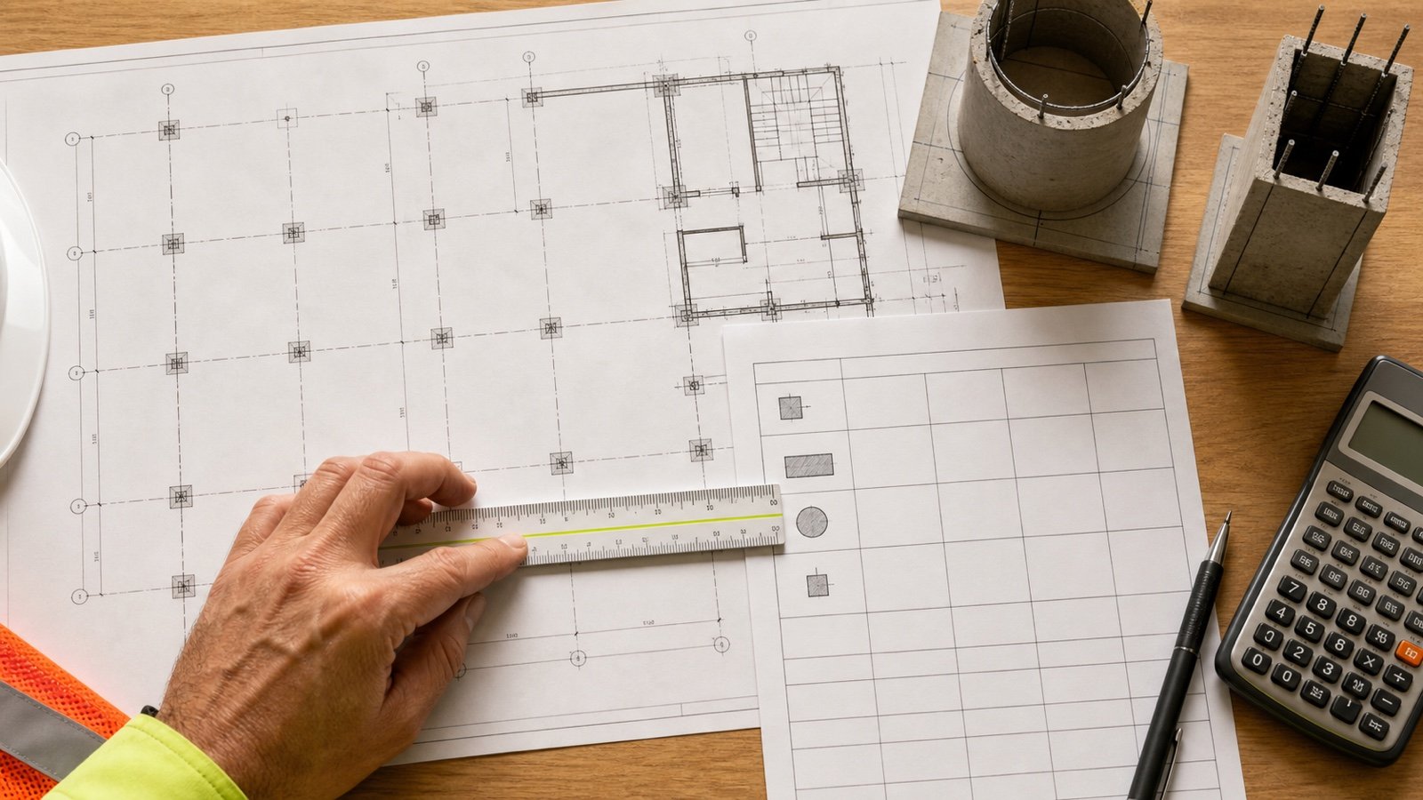
Start from the current concrete boundary, formwork plan and placement sequence. Mark every surface on a plan or section before entering its length and height.
| Field | Record |
|---|---|
| Surface ID | Unique mark tied to the plan, section or model |
| Placement phase | Pour number, strip or sequence where the form is used |
| Contact run | Length measured at the accepted concrete face |
| Contact height | Vertical or sloped form dimension touching concrete |
| Number of faces | One edge face or the verified count for a custom row |
| Surface state | Outside edge, blockout, stop end, soffit or other identified face |
| Source | Drawing, detail, formwork plan and revision |
| Status | Included, excluded, revised or awaiting clarification |
Use the inside concrete face when the board sits outside the finished slab boundary. A board's full height can extend above or below the concrete contact surface, so its product dimension may exceed the formed height used in the area calculation.
What formulas apply to a slab edge?
A constant-height edge uses length multiplied by formed height. Convert both dimensions into compatible units before multiplication.
Constant-height edge area = formed run × formed height
Rectangular outside perimeter = 2 × (length + width)
Rectangular blockout perimeter = 2 × (blockout length + blockout width)
Linear height-transition area = run × (start height + end height) ÷ 2
Use the last formula only when the accepted contact face changes linearly between 2 verified heights. A step needs separate constant-height rows. Curved or irregular faces need their measured surface geometry.
Metric example: outside edges, blockout and stop end
An 8 m by 5 m slab-on-ground has 150 mm formed outside edges. One 1.2 m by 0.8 m full-depth blockout and one 3 m internal stop end use the same 150 mm contact height.
| Row | Calculation | Contact area |
|---|---|---|
| Outside perimeter | 2 × (8 + 5) | 26.000 m run |
| Outside edge faces | 26 × 0.150 | 3.900 m² |
| Blockout perimeter | 2 × (1.2 + 0.8) | 4.000 m run |
| Blockout faces | 4 × 0.150 | 0.600 m² |
| Stop end | 3 × 0.150 | 0.450 m² |
| Total contact area | 3.900 + 0.600 + 0.450 | 4.950 m² |
The listed contact runs total 26 + 4 + 3 = 33 m. The schedule therefore reports 33 linear metres and 4.950 square metres. It does not convert either result into a board count.
Why is linear form run different from contact area?
Linear run describes the path length along the concrete face. Contact area adds the height that touches concrete.
A 12 m edge with a 100 mm formed height has 12 m of run and 1.200 m² of contact area. The same 12 m run at 250 mm has 3.000 m² of contact area.
Board lengths, joints, corner details and cut pieces can depend on the 12 m run. Release-agent coverage or a surface-area payment item can depend on square area. Keep both units visible so one cannot be substituted for the other.
How do blockouts and stop ends change the area?
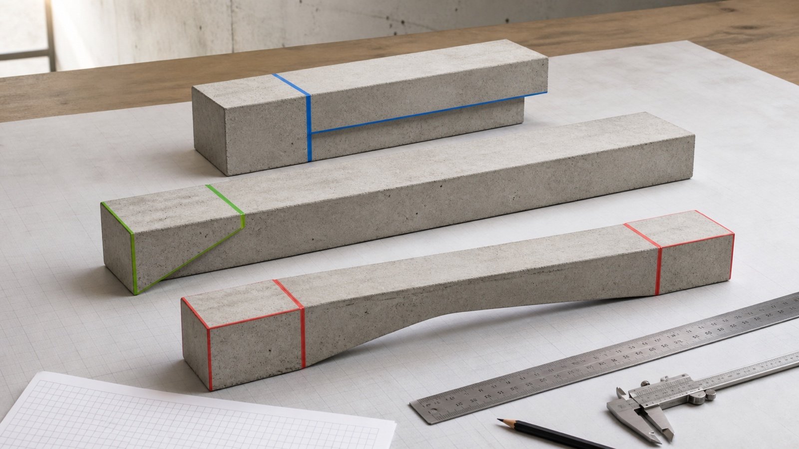
An internal blockout adds vertical contact faces around its perimeter. A stop end adds the face that retains concrete at the boundary of one placement.
Assign each stop end to a placement phase. A board can retain the first pour, move, and retain another pour later. The geometric surface schedule can contain both uses, while a simultaneous material schedule needs the sequence and planned reuse.
| Condition | Area treatment |
|---|---|
| Full-depth rectangular blockout | Blockout perimeter × formed depth |
| Partial-depth recess formed from the top | Verified recess side faces; the retained slab remains below |
| Stop end across uniform slab depth | Stop length × retained depth |
| Stop end crossing a thickened strip | Separate the uniform and deeper contact sections |
| Permanent sleeve or leave-in component | Record under the project's permanent-form or embed rule |
| Shared boundary between placement phases | Record the physical use by phase and prevent simultaneous material duplication |
How is a suspended slab measured?
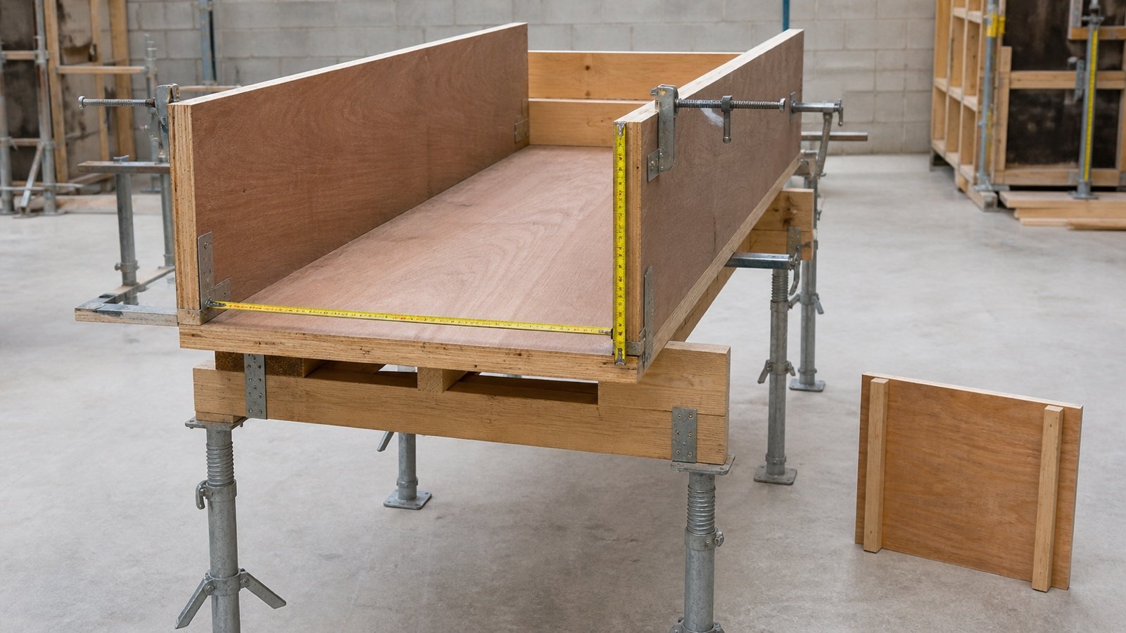
A suspended slab can include a formed soffit, outside edge faces and opening side faces. Deduct a full opening from the soffit geometry, then add its formed vertical sides when those surfaces touch forms.
A 6 m by 4 m slab has one 1.0 m by 0.8 m full opening and a 200 mm slab depth:
- Gross soffit: 6 × 4 = 24.000 m².
- Opening removed from soffit: 1.0 × 0.8 = 0.800 m².
- Net soffit: 23.200 m².
- Outside edge: 2 × (6 + 4) × 0.200 = 4.000 m².
- Opening sides: 2 × (1.0 + 0.8) × 0.200 = 0.720 m².
- Geometric contact total: 23.200 + 4.000 + 0.720 = 27.920 m².
This fixture checks geometric contact. Contract measurement rules can use opening thresholds or other payment conventions. Record that rule beside the bid or payment quantity instead of changing the geometry without a note.
How do changing edge heights affect the result?
Create a row whenever the formed height or face geometry changes. A verified straight transition between 2 heights can use its average contact height.
| Row | Calculation | Area |
|---|---|---|
| Run A | 18 ft × 5 in ÷ 12 | 7.500000 ft² |
| Run B | 12 ft × 8 in ÷ 12 | 8.000000 ft² |
| Run C, linear 5 to 11 in | 10 ft × ((5 + 11) ÷ 2) ÷ 12 | 6.666667 ft² |
| Stop end | 6 ft × 5 in ÷ 12 | 2.500000 ft² |
| Total | Sum of unrounded rows | 24.666667 ft² |
The 4 listed runs total 46 ft. Run C can use the average because the fixture defines a planar transition. Field waves, bowed boards, stepped details and unknown excavation faces need a different record.
Does a thickened slab edge use the full depth?
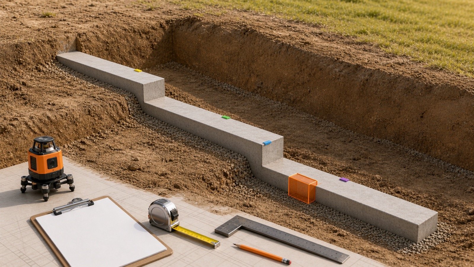
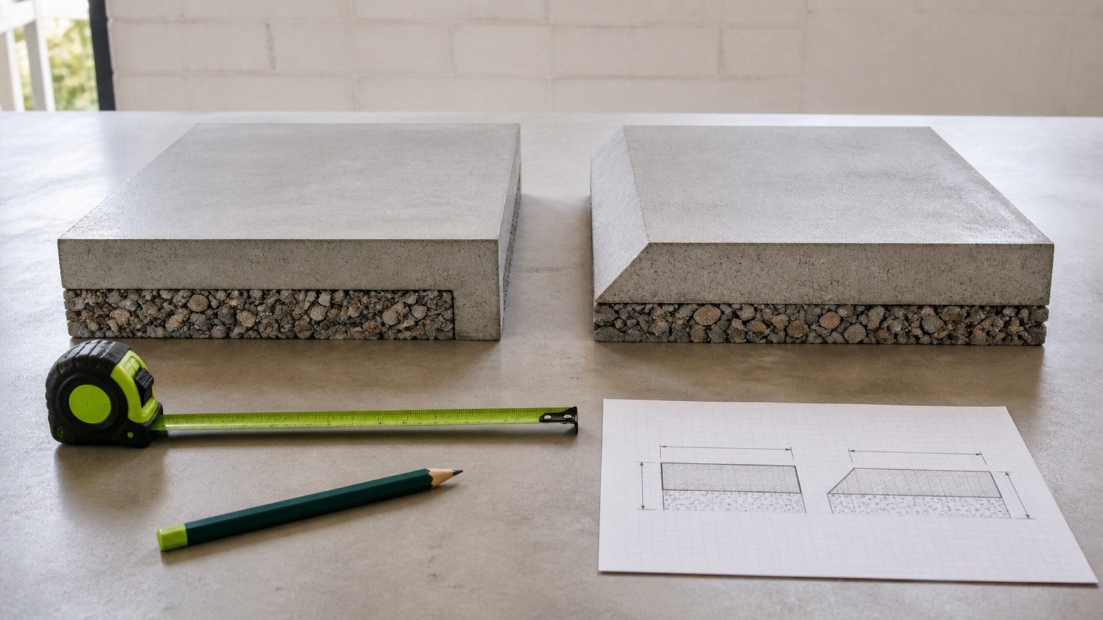
Use the actual height of each temporary contact face. A turned-down edge can have one formed outside face while its underside and inner slope bear against prepared ground, insulation or another permanent boundary.
Read the section and construction method together. If a 400 mm total edge depth has 250 mm of temporary form contact above the accepted base or excavation interface, that row uses 250 mm. Another project can form the complete 400 mm face.
The Concrete Slab Thickness guide explains how to identify the accepted top and bottom boundaries. The Concrete Slab Volume guide handles the concrete inside thickened edges and internal strips.
Can contact area be converted into boards or panels?
Convert geometry into materials after the form system and stock are confirmed. You need usable board or panel dimensions, joint layout, corners, cuts, support spacing, braces, ties, damage allowance, reuse cycles and the placement sequence.
| Record | Why it affects materials |
|---|---|
| Linear run by height | Controls board courses, panel orientation and joints |
| Contact area | Supports surface coverage and system-area checks |
| Stock dimensions | Sets the available length and face size before cuts |
| Corner and stop details | Changes joints, closures and cut pieces |
| Placement sequence | Controls which components can be reused |
| Approved support design | Sets stakes, braces, ties, shores and connections |
| Supplier and project rules | Set package, rental, return and measurement conditions |
Use the Concrete Slab Calculator to check the concrete footprint and volume before reconciling the form schedule. The Footing Formwork Area guide covers strip and pad footing faces where ground contact, ends and reuse create a different schedule.
Which mistakes change the formwork takeoff?
- Multiplying the slab plan area by its thickness for edge formwork.
- Reporting perimeter length as square contact area.
- Using the board's nominal size as the concrete contact height.
- Counting the slab-on-ground underside as temporary formwork without a formed surface.
- Missing internal blockout and stop-end faces.
- Deducting an opening from the soffit while omitting its formed side faces.
- Using one height for stepped or changing edge sections.
- Counting a shared stop end as simultaneous material in 2 placement phases.
- Adding surfaces cast against permanent deck, insulation or accepted ground to a temporary-form total.
- Rounding every row before adding the schedule.
- Turning square area into board, panel or support counts without stock and system data.
- Using a quantity schedule as approval for formwork design or removal.
What design and safety limits apply?
Formwork must carry fresh-concrete, construction and other anticipated loads within the rules that apply to the project. OSHA 1926.703 requires covered U.S. formwork to be designed, fabricated, erected, supported, braced and maintained for those loads. It also addresses jobsite drawings, shoring, reshoring, inspection and form removal.
ACI 347R-14 covers contract information, design, loads, shores, bracing, construction, inspection, removal and special form systems. ACI's committee listing identifies the guide as reapproved in 2021.
This geometry guide does not select lumber, panels, stakes, ties, braces, shores, release agents, working platforms, tolerances, placement rate or removal time. Follow the current formwork plan, project documents, manufacturer instructions, local requirements and qualified design.
Return to the Concrete Planning hub for related slab, footing, reinforcement and supply resources.
Sources and source scope
- ACI 347R-14 public preview, Guide to Formwork for Concrete: document scope, contract-information, design, load, bracing, construction, inspection and removal topics.
- ACI Committee 347 page: current public listing of PRC-347-14(21) as reapproved in 2021.
- OSHA 29 CFR 1926.700: the cited formwork definition and U.S. scope.
- OSHA 29 CFR 1926.703: covered U.S. formwork, drawings, shoring, inspection and removal requirements.
- NIST Handbook 133 (2026), Appendix E: unit relationships used to check the metric and imperial fixtures.
Source scope: ACI and OSHA support the formwork-system, design, construction and safety boundaries. NIST supports the unit relationships. The contact-area formulas and examples use independently checked geometry. These sources do not approve a project surface list, payment rule, material count, reuse cycle, support layout, form removal decision or cost.
The calculation methodology explains unit conversion, precision, assumptions and corrections.
Review note: Saleem Sial owns the research and editorial record. Arithmetic fixtures, source checks, build validation and rendered QA form the internal publication gate. Waseem Sial, External Reviewer and Engineer, is listed for ongoing external review; no completed review date is claimed.