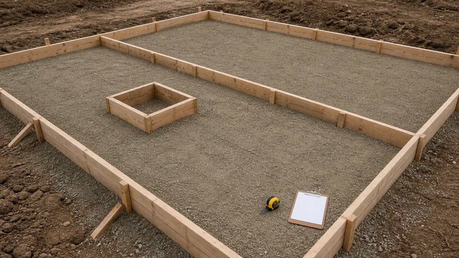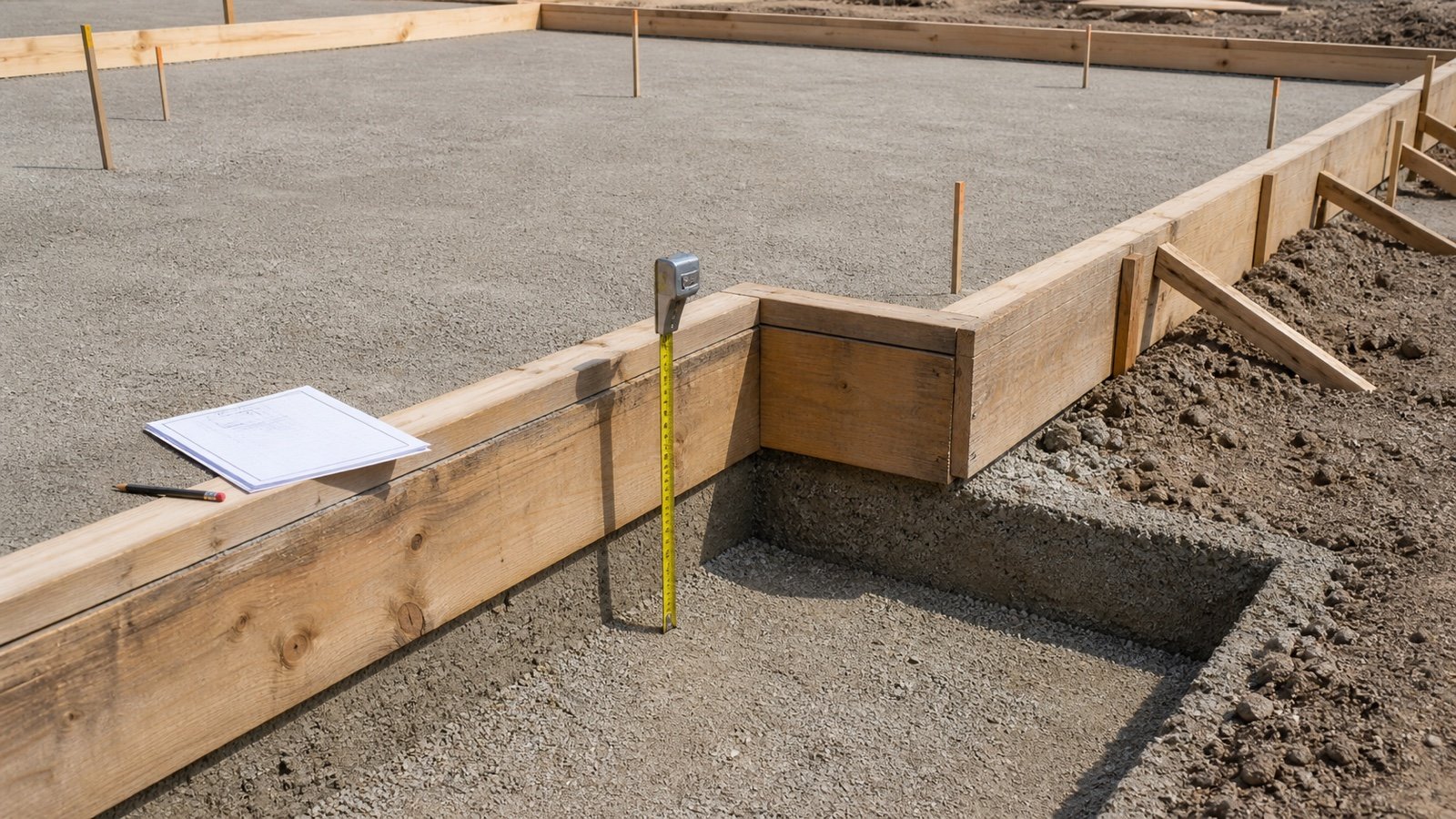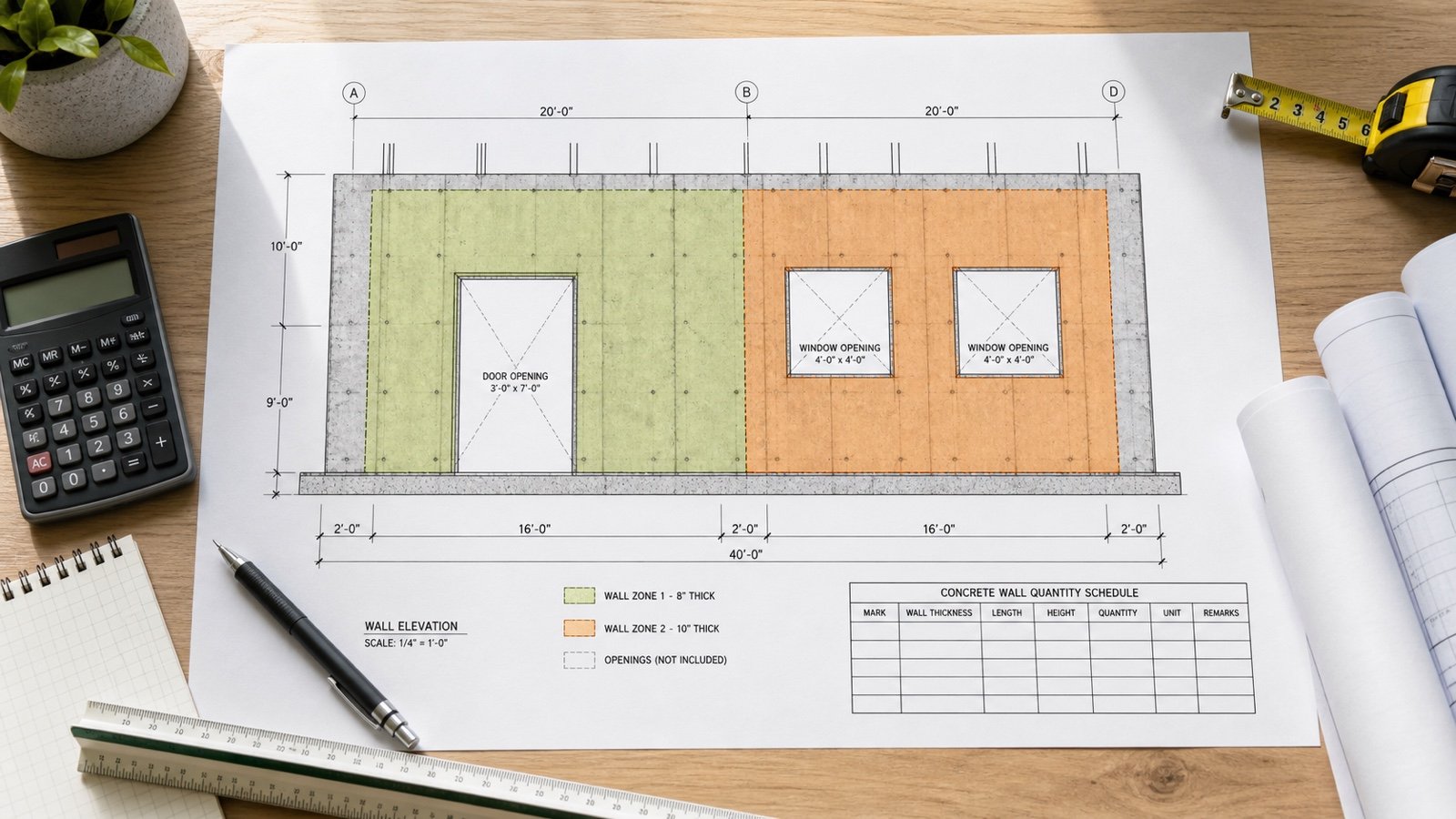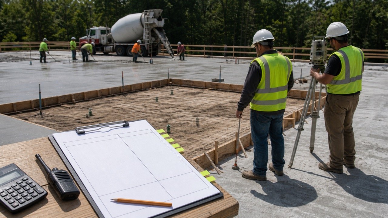
Strip-footing volume depends on length, but drawings can dimension that length to an outside face, inside face, wall centreline, footing centreline, or clear gap. Mixing those references can count a corner twice or leave part of a junction out.
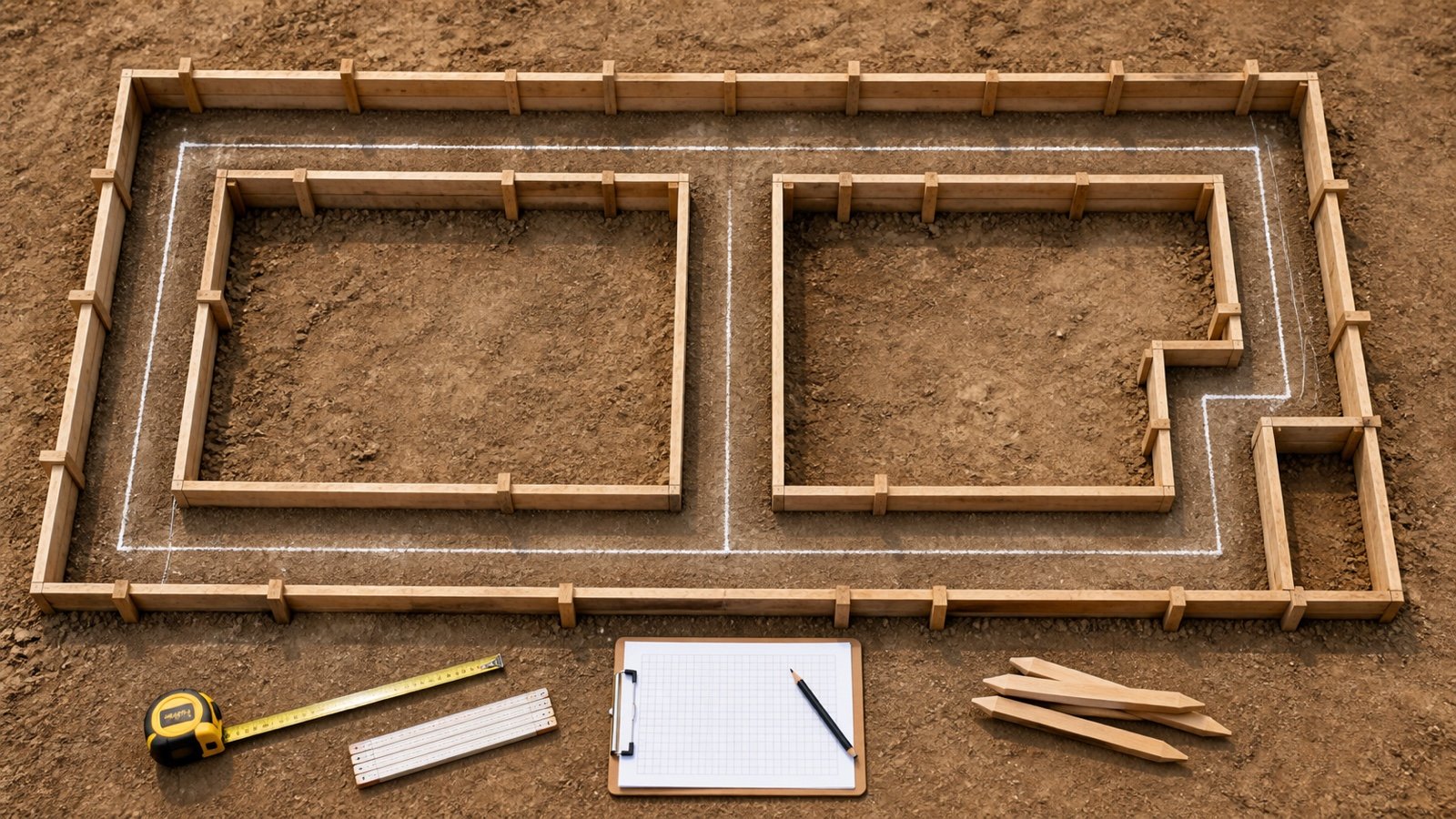
Mark the measurement boundary before adding dimensions. Use one stated convention for each connected footing group, and keep internal runs, width changes, steps, pads, and revisions on identified takeoff lines.
Which length should you use for a strip footing?
Use the length along the centre of the concrete strip when the footing has a constant cross-section and the plan provides or supports that centreline. If the drawing gives outside, inside, or clear dimensions, convert them with the actual geometry or schedule non-overlapping rectangular solids.
A final length without a reference line cannot show whether corners and junctions are already included. Record the drawing, revision, footing mark, dimension endpoints, width, depth, and intersection treatment beside the number.
An outside wall dimension, an outside footing dimension, and an excavation dimension can have different offsets. The adjustment uses the width of the object behind the dimension, not a universal footing-width deduction.
What do centreline, outside and clear-run lengths mean?
| Convention | Endpoints | Main check |
|---|---|---|
| Footing centreline | Along the middle of the concrete strip | Connected lines meet once at each centreline node |
| Outside footing dimension | Outside concrete face to outside concrete face | Convert the perimeter or deduct overlapping corner solids |
| Inside footing dimension | Inside concrete face to inside concrete face | Add the correct offsets to reach the centreline |
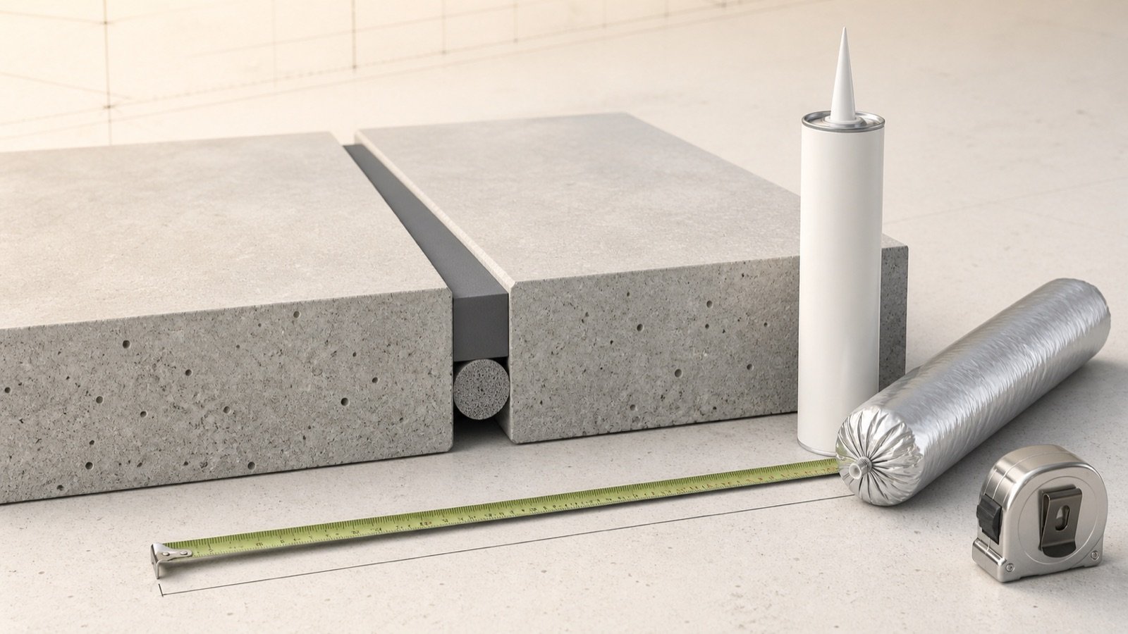
| Clear run | Face of one concrete section to the face of another | The adjoining section usually supplies the junction volume |
| Outside wall dimension | Outside face of the wall above | Use the wall-to-footing alignment shown by the detail |
| Excavation length | As-dug or design excavation boundary | Keep excavation and concrete quantities separate |
The BC Carpenter Apprenticeship Program defines centreline perimeter as the distance around a foundation measured at the centreline and describes it as the average of the inside and outside perimeters. Its rectangular example reduces the outside building perimeter by 4 wall thicknesses because the stated dimensions refer to the outside of the foundation wall.
How do you calculate the centreline of a rectangular footing?
When the known dimensions are the outside faces of a uniform rectangular concrete strip, subtract one strip width from each outside plan dimension, then calculate the perimeter.
Centreline perimeter = 2 × [(outside length − strip width) + (outside width − strip width)]
Equivalent form = outside perimeter − 4 × strip width
A rectangular footing has outside concrete dimensions of 12 m by 8 m and a uniform width of 0.50 m:
- Outside perimeter: 2 × (12 + 8) = 40 m.
- Centreline length dimension: 12 − 0.50 = 11.50 m.
- Centreline width dimension: 8 − 0.50 = 7.50 m.
- Centreline perimeter: 2 × (11.50 + 7.50) = 38.00 m.
- At 0.50 m wide and 0.25 m deep, concrete volume is 38 × 0.50 × 0.25 = 4.750 m³.
Multiplying the 40 m outside perimeter by the footing cross-section would give 5.000 m³. It overstates this fixture by 0.250 m³ because the 4 corner squares are counted through the outside-length convention.
How can the inside and outside perimeters check the result?
For the same uniform rectangle, the centreline perimeter equals the average of the inside and outside concrete perimeters. This provides an independent check.
The inside dimensions are 12 − 2(0.50) = 11 m and 8 − 2(0.50) = 7 m. The inside perimeter is 2 × (11 + 7) = 36 m. The check is (40 + 36) ÷ 2 = 38 m.
This shortcut applies to a closed, uniform-width rectangular ring. It does not resolve unequal widths, open ends, curved runs, offset walls, pads, or an irregular plan without section-by-section geometry.
Does an outside wall dimension use the footing width?
Use the width of the dimensioned wall when the plan dimension runs to the outside wall faces and the wall centreline aligns with the footing centreline. The footing may project beyond the wall, but that projection does not move the shared centreline.
For a 12 m by 8 m outside wall rectangle with a uniform 0.20 m wall, the wall centreline perimeter is 2 × [(12 − 0.20) + (8 − 0.20)] = 39.20 m. A centred 0.60 m footing below follows the same 39.20 m line.
Using 0.60 m in the outside-wall formula would calculate 37.60 m and understate the centreline by 1.60 m. Check whether the dimension belongs to the wall, footing, grid, property line, excavation, or another reference before applying an offset.
How should an L-corner be measured?
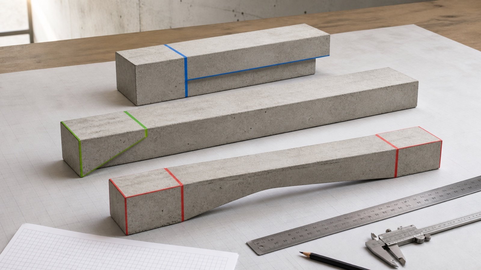
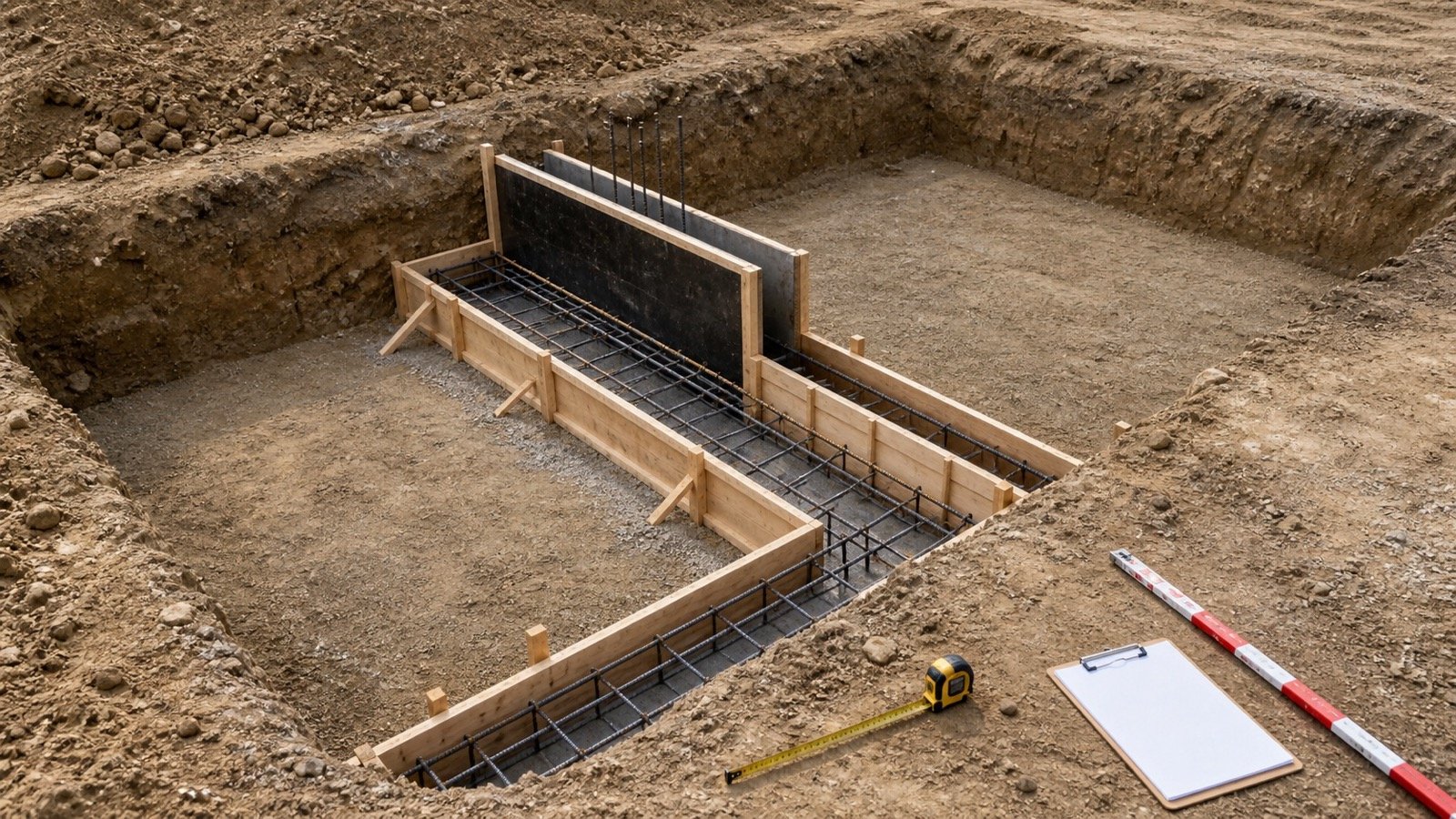
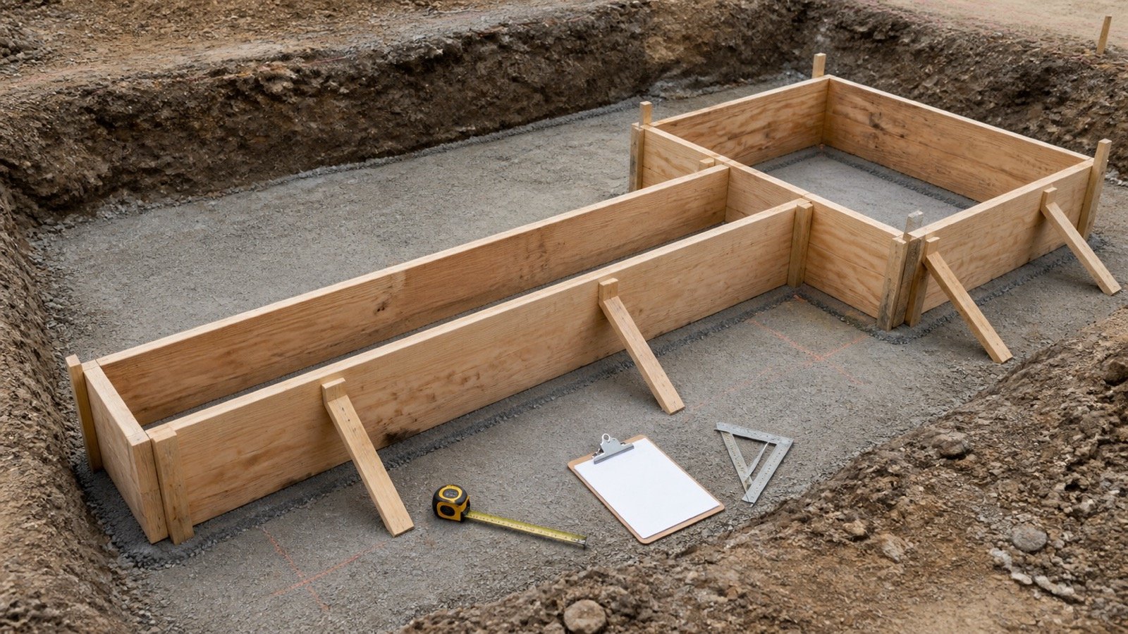
Trace the centreline through the corner as one continuous path, or calculate the union of 2 rectangular solids. Both methods can produce the same quantity when the endpoints are defined consistently.
For equal-width strips, outside-to-outside leg dimensions include a shared corner square. Converting each leg to its centreline endpoint, or subtracting the duplicated square from gross rectangles, removes one copy of that overlap.
| Method | Corner treatment | Record needed |
|---|---|---|
| Continuous centreline | Turn once at the common centreline node | Polyline or dimension chain showing endpoints |
| Non-overlapping clear rectangles | Stop one leg at the face of the other | Which leg supplies the corner |
| Gross outside rectangles | Subtract the exact shared corner prism once | Overlap length, width, vertical overlap, and level |
How should a T-junction be measured?
Use a clear-run branch that stops at the near face of the main strip when the main strip already supplies the full junction. This creates 2 non-overlapping rectangles and needs no deduction.
If the branch length continues from its remote end to the main-strip centreline, half of the junction lies inside both rectangular lines for equal aligned widths. Deduct the shared half-junction prism, or shorten the branch by half the main-strip width before multiplying.
Equal-depth T overlap = branch width × (main width ÷ 2) × common vertical depth
Example: a 0.40 m branch meets the side of a 0.60 m main strip, and both occupy the same 0.25 m depth. A branch measured to the main centreline overlaps 0.40 × 0.30 × 0.25 = 0.030 m³. A branch measured only to the main strip's near face has no geometric overlap.
The competing methods are both valid when their endpoints and deductions match. Applying a half-width deduction to a branch that already stops at the concrete face would omit material.
How should a cross-junction be measured?
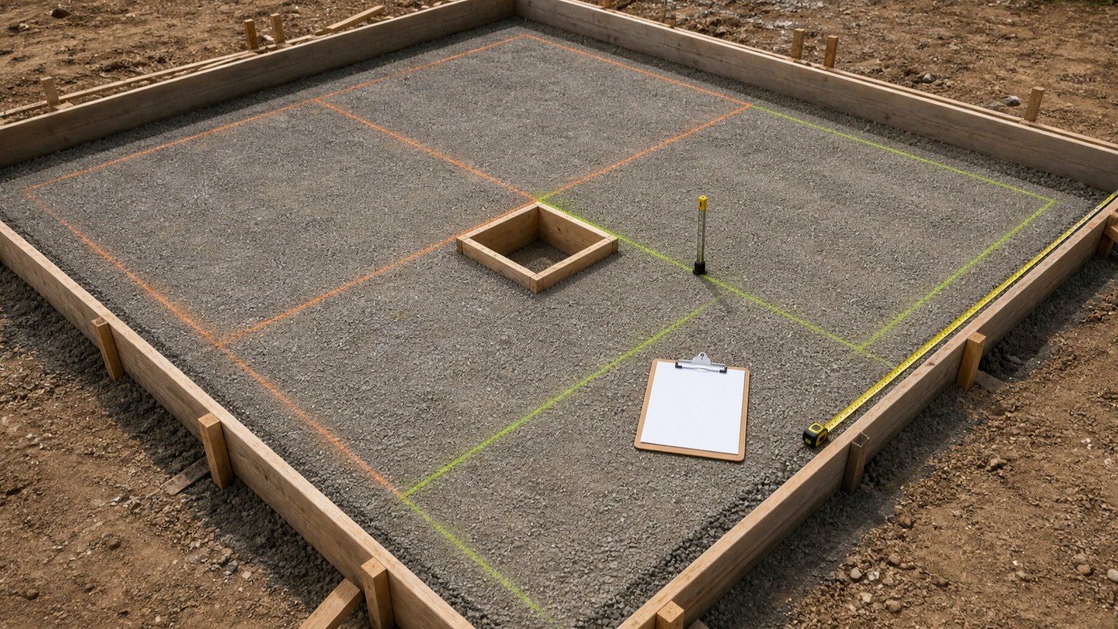
When 2 full strip rectangles cross, subtract the shared intersection prism once. If the secondary strip is split into 2 clear runs that stop at the main strip faces, the rectangles do not overlap.
Aligned cross overlap = first strip width × second strip width × common vertical depth
For a 0.60 m main strip crossing a 0.40 m strip at the same 0.25 m depth, the duplicated volume is 0.60 × 0.40 × 0.25 = 0.060 m³.
A centreline total produced by software can already resolve the node. Do not add another junction deduction until the software's measurement convention, geometry, and exported quantities are checked.
What changes when strip widths or depths differ?
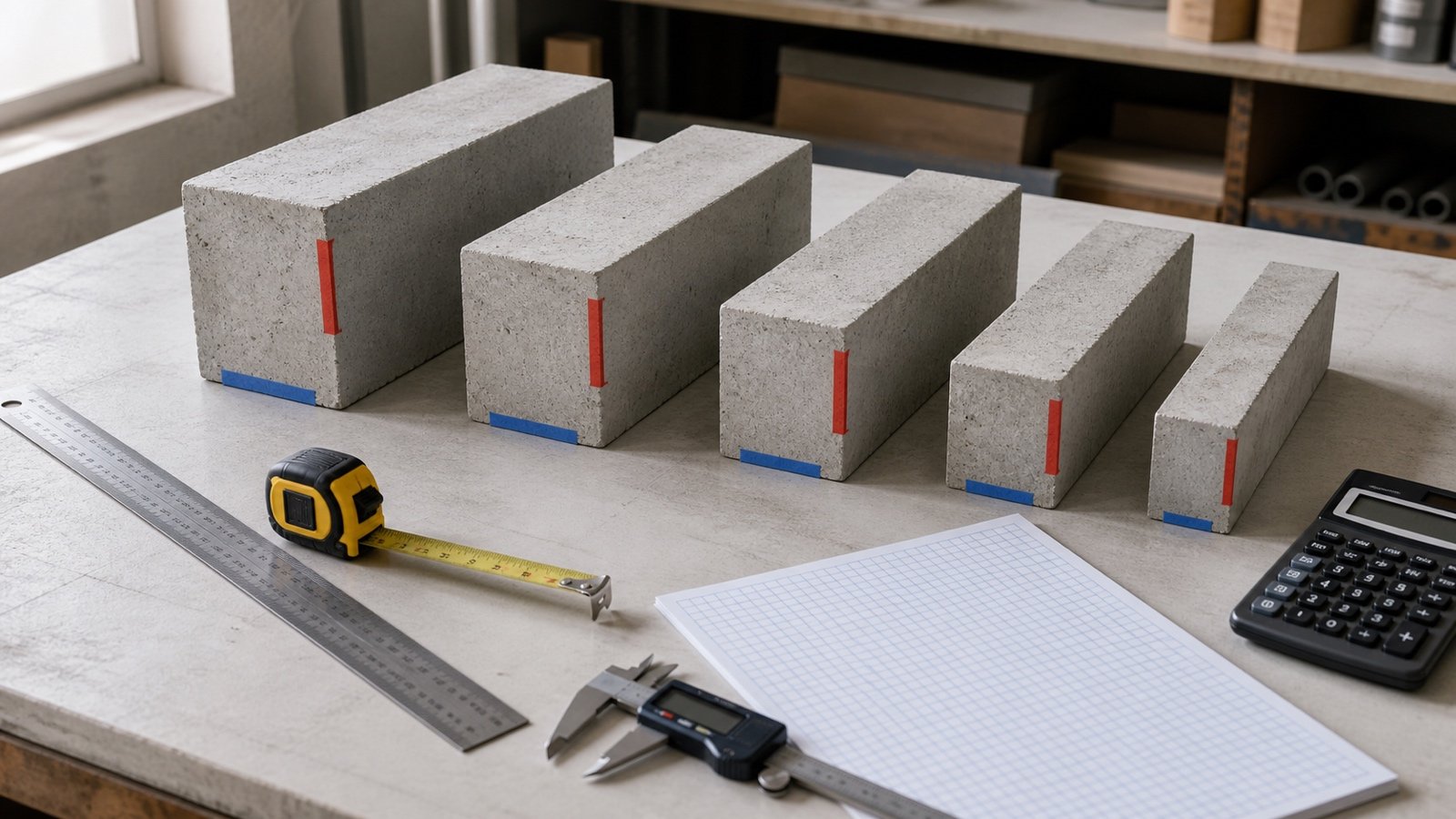
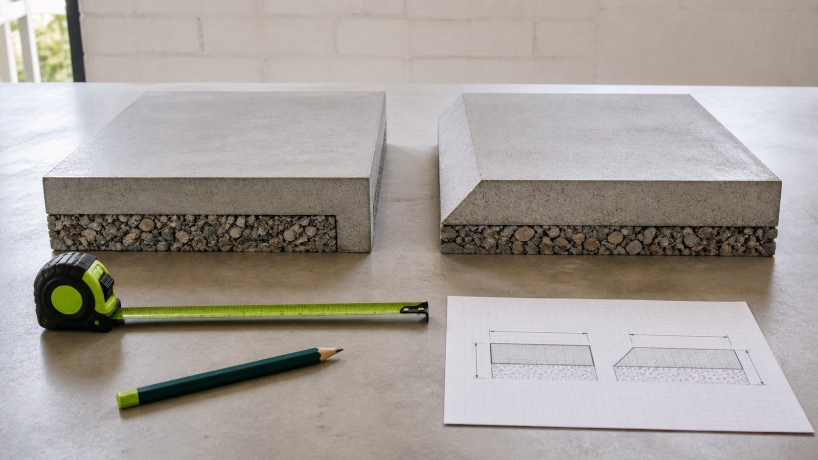
Use the actual shared plan area and vertical overlap. A generic half-width or full-width rule can fail when the strips have unequal widths, offset centrelines, different top or bottom levels, steps, slopes, keys, or thickened junctions.
For aligned rectangular strips, shared plan area is the product of their widths. The vertical overlap is the height occupied by both solids, based on their actual top and bottom levels. It is not automatically the smaller listed depth when the sections sit at different elevations.
Split the work at every width, depth, or level change. Preserve footing marks and detail references so the checker can reconstruct the overlap instead of trusting one adjustment number.
How should jogs and re-entrant corners be handled?
Trace every change of direction on the chosen reference line. A rectangular bump-out adds its outward and return legs. A re-entrant notch changes the inside and outside perimeters but can leave the centreline total unchanged only under a specific balanced geometry.
Do not use the claim that every jog cancels. Sketch the centreline or build non-overlapping rectangles. Check that the traced path closes and that horizontal and vertical coordinate changes balance around a closed footprint.
When is the centreline method unsuitable?
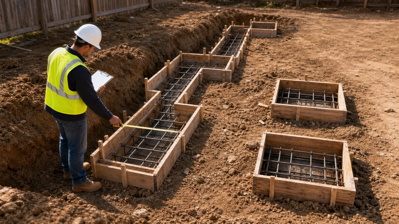
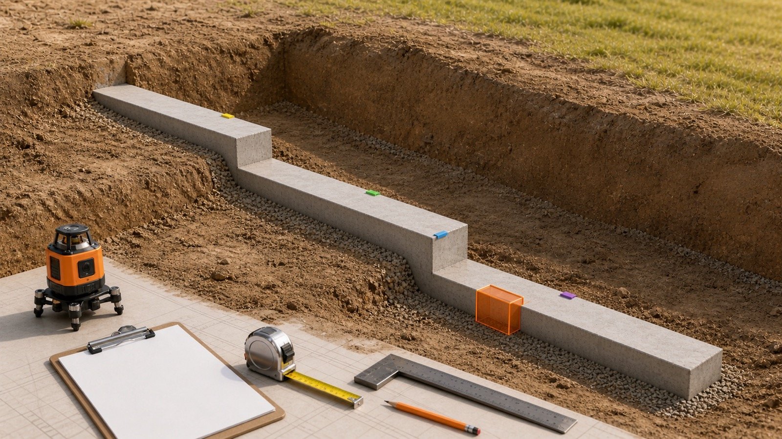
Use a section or solid schedule when the connected footing does not have one constant cross-section. Centreline length alone cannot preserve a width change, step, isolated pad, thickened junction, curved segment, sloped face, pile cap, pedestal, grade beam, or combined footing.
- Separate each constant-width and constant-depth strip.
- Calculate pads and other solids on their own lines.
- Use valid arc geometry for curved centrelines.
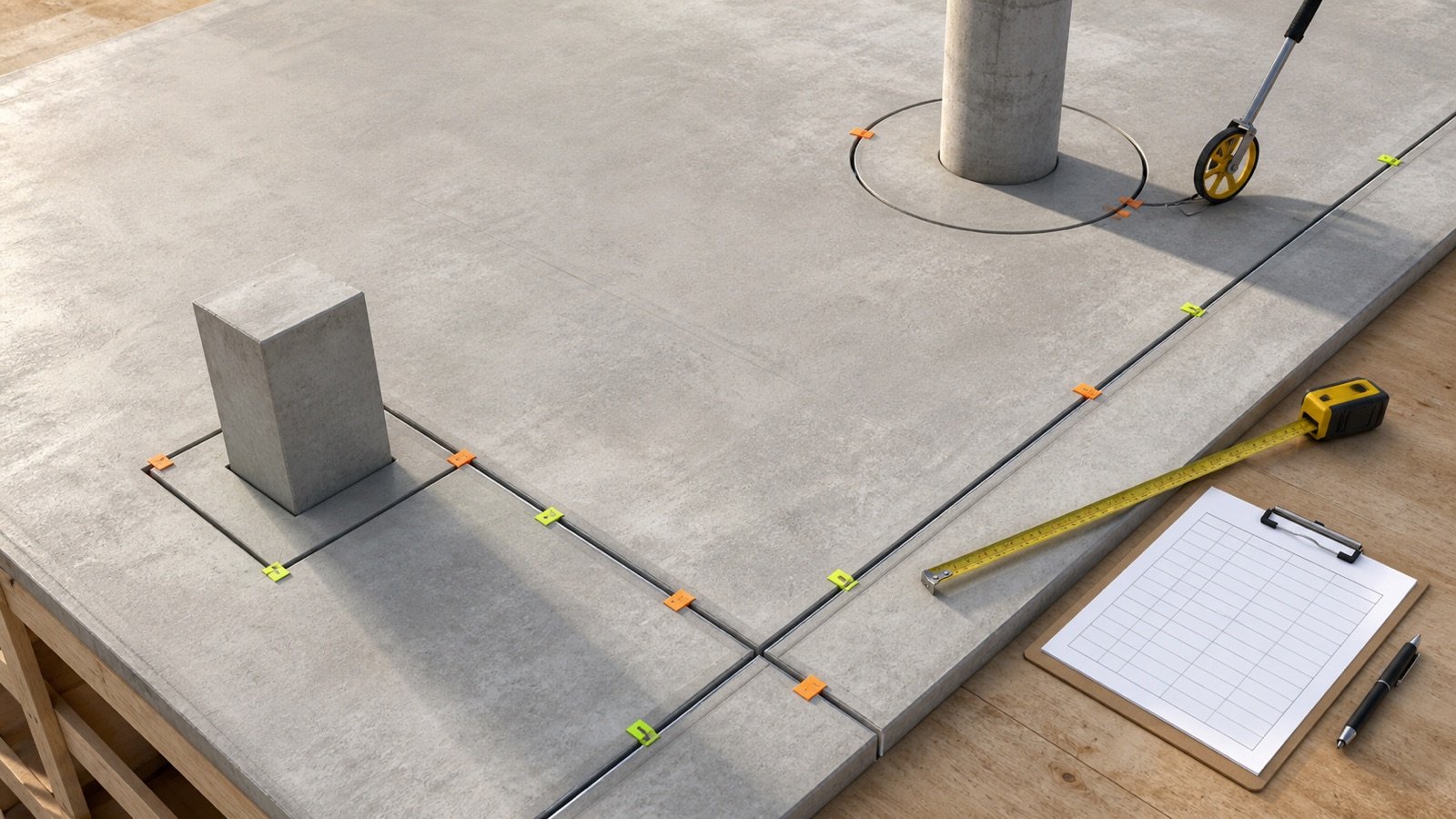
- Record openings or blockouts only when the approved concrete boundary excludes them.
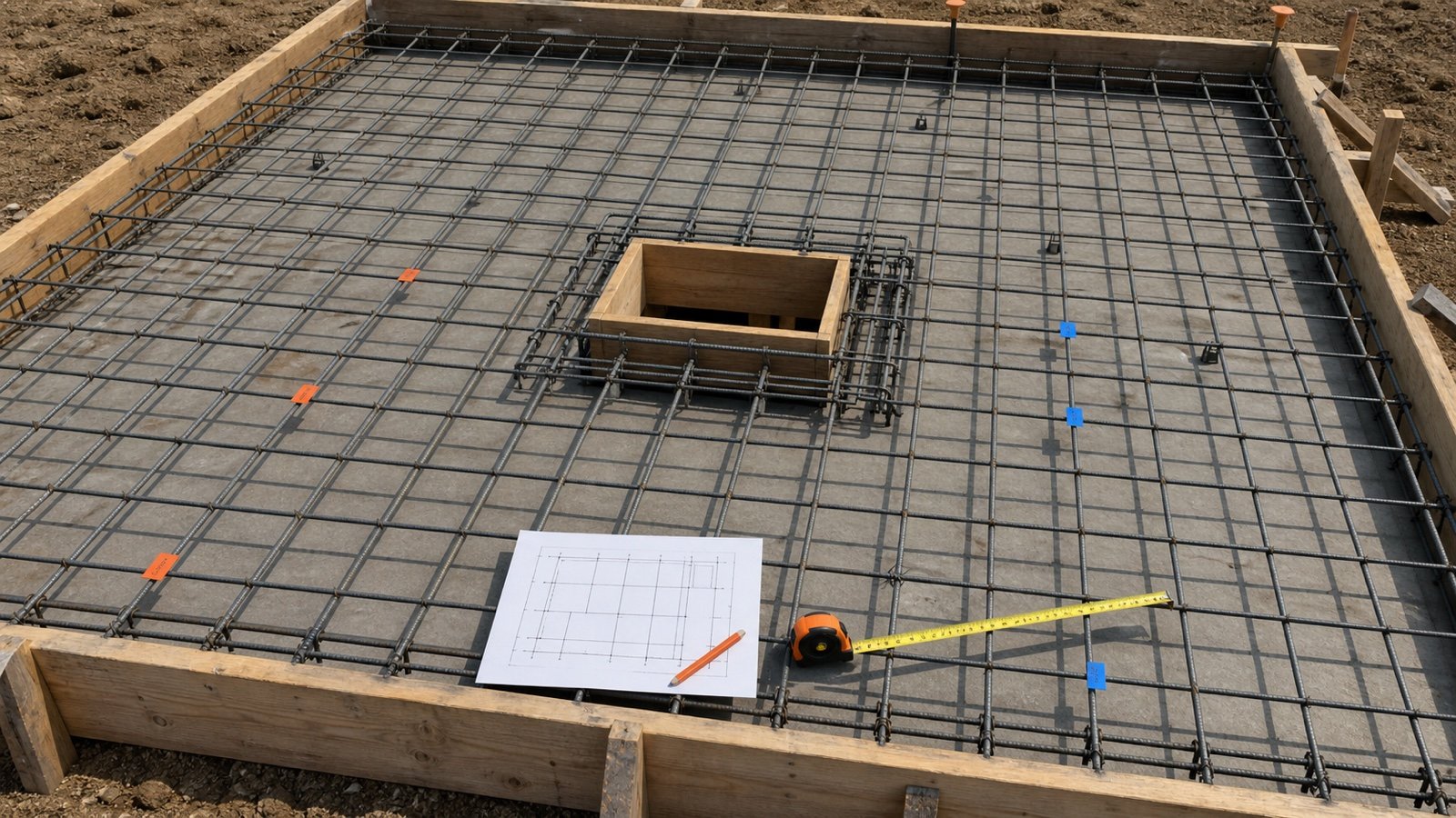
- Keep reinforcement, forms, excavation, blinding, walls, and backfill in their own quantity records.
How do you transfer the checked length into concrete volume?
Multiply each verified length by the matching concrete width and depth in compatible units. Add unrounded section volumes, then apply any verified overlap correction that remains.
Strip volume = checked length × concrete width × concrete depth
Enter the sections in the Concrete Footing Calculator. Use its intersection-deduction field only when the entered section rectangles still duplicate a verified solid. The Concrete Footing Volume guide covers pads, steps, field changes, and supply handoff.
What should you check before accepting a takeoff length?
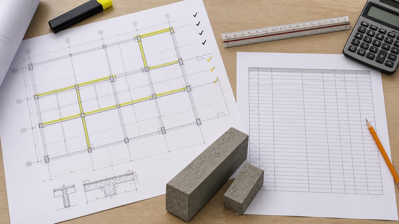
- Confirm the current drawing, scale, units, footing marks, sections, and revisions.
- Highlight only the concrete strips in scope.
- Label every dimension as centreline, outside, inside, grid, or clear.
- Trace perimeter and internal runs separately.
- Record the endpoint treatment at L, T, and cross junctions.
- Separate width, depth, and level changes.
- Reconcile a centreline calculation with an area-union or gross-minus-overlap check.
- Keep the unrounded length and volume schedule.
- Have another person check the marked plan and arithmetic where the project process requires it.
Common strip-footing length mistakes
- Subtracting footing width from dimensions that refer to the wall above.
- Adding outside-face lengths and multiplying by width without correcting corners.
- Applying a junction deduction to a clear run that already stops at the adjoining face.
- Counting one centreline node twice.
- Using one cross-section across changed widths or steps.
- Treating excavation length as footing-concrete length.
- Assuming a software polyline uses the intended face or centreline.
- Scaling a dimension that the current drawing already states.
- Missing a jog, internal strip, or revised footing mark.
- Rounding each leg before the schedule is added.
Return to the Concrete Planning hub for footing, packaged-concrete, ready-mix, reinforcement, block, and joint resources.
Sources and source scope
- BC Carpenter Apprenticeship Program, Level 4, Competency G-8: centreline-perimeter definition, average of inside and outside perimeters, rectangular outside-perimeter adjustment, corner-overlap explanation, jog example, and rectangular concrete-volume formula.
- NIST Handbook 133 (2026), Appendix E: unit relationships used for metric and U.S. customary checks.
Source scope: The BC training module supports the stated uniform rectangular foundation examples and volume method. NIST supports unit relationships. L-, T-, and cross-junction fixtures on this page are independently derived rectangular-solid checks. These sources do not select footing size, structural layout, length convention, excavation boundary, design, allowance, concrete mixture, supplier order, or field change for a project.
Review note: Saleem Sial owns the research and editorial record. Formula fixtures, source checks, build validation, and rendered QA form the internal publication gate. Waseem Sial, External Reviewer and Engineer, is listed for ongoing external review; no completed review date is claimed.