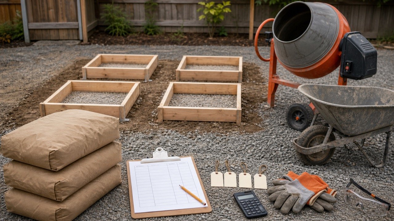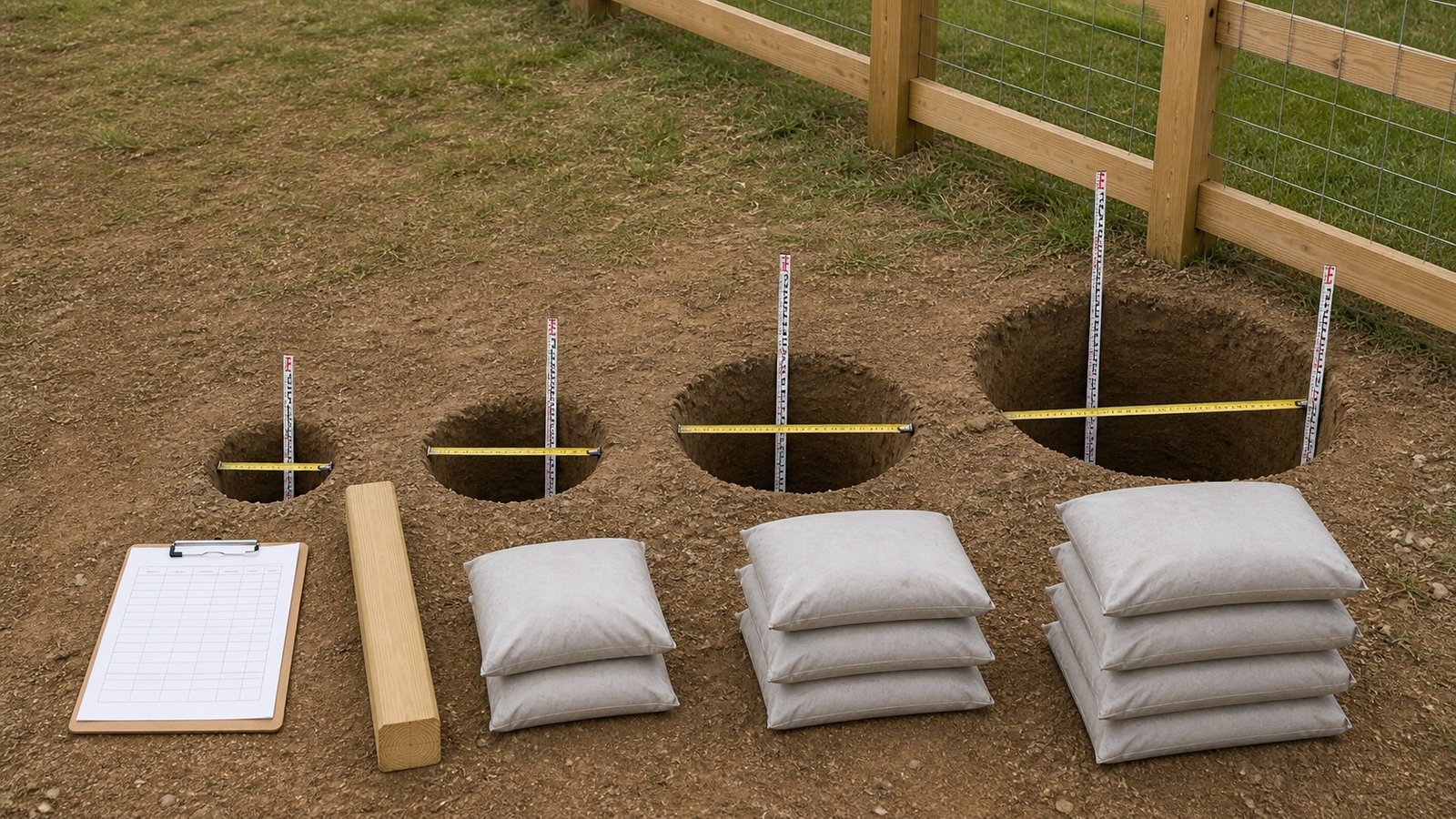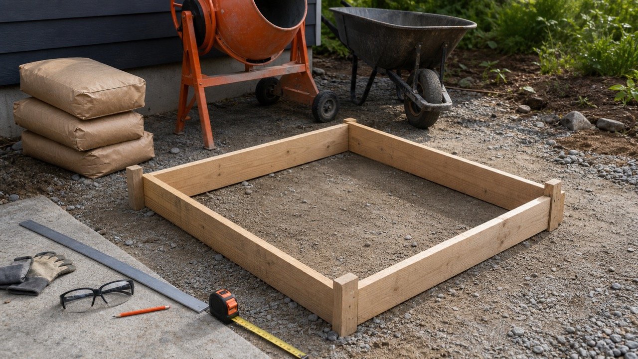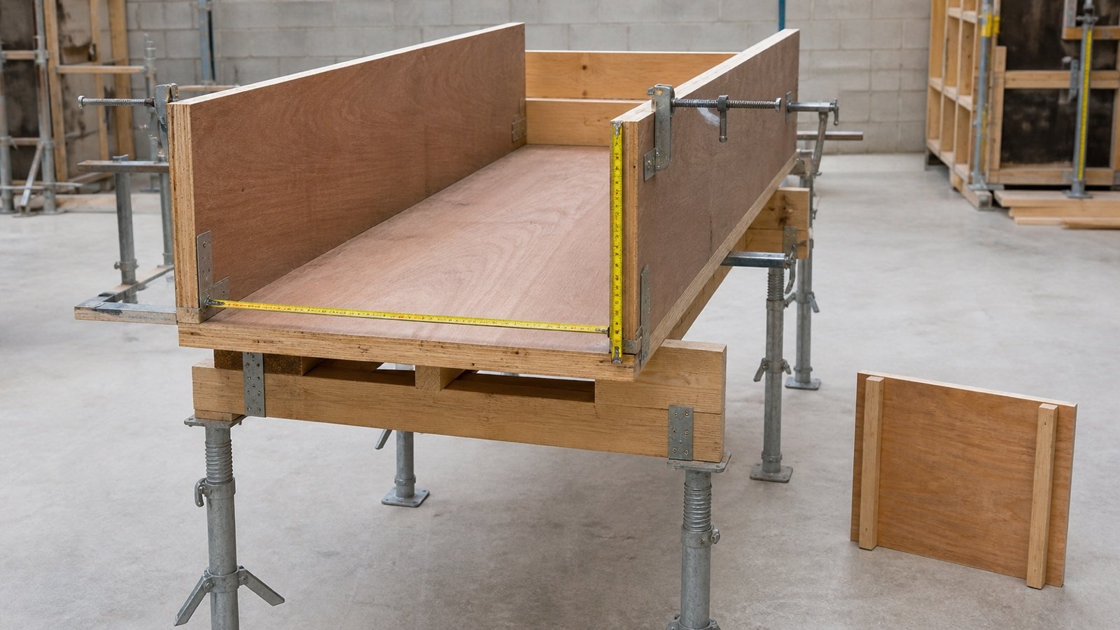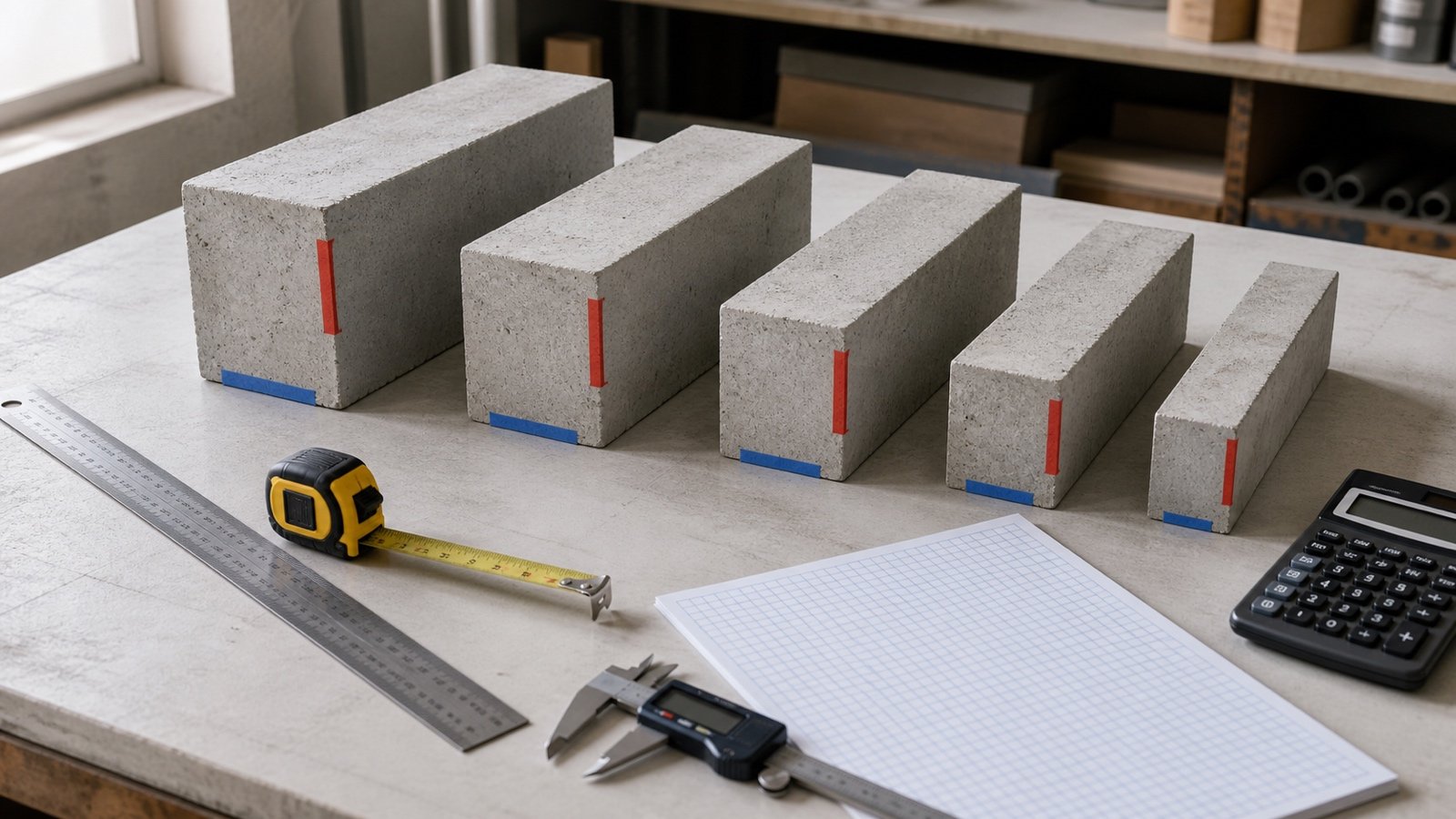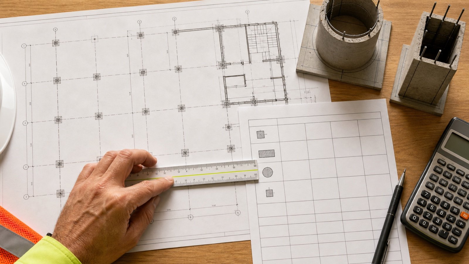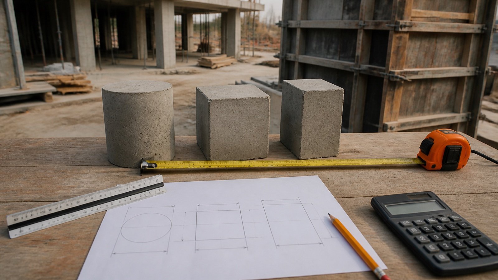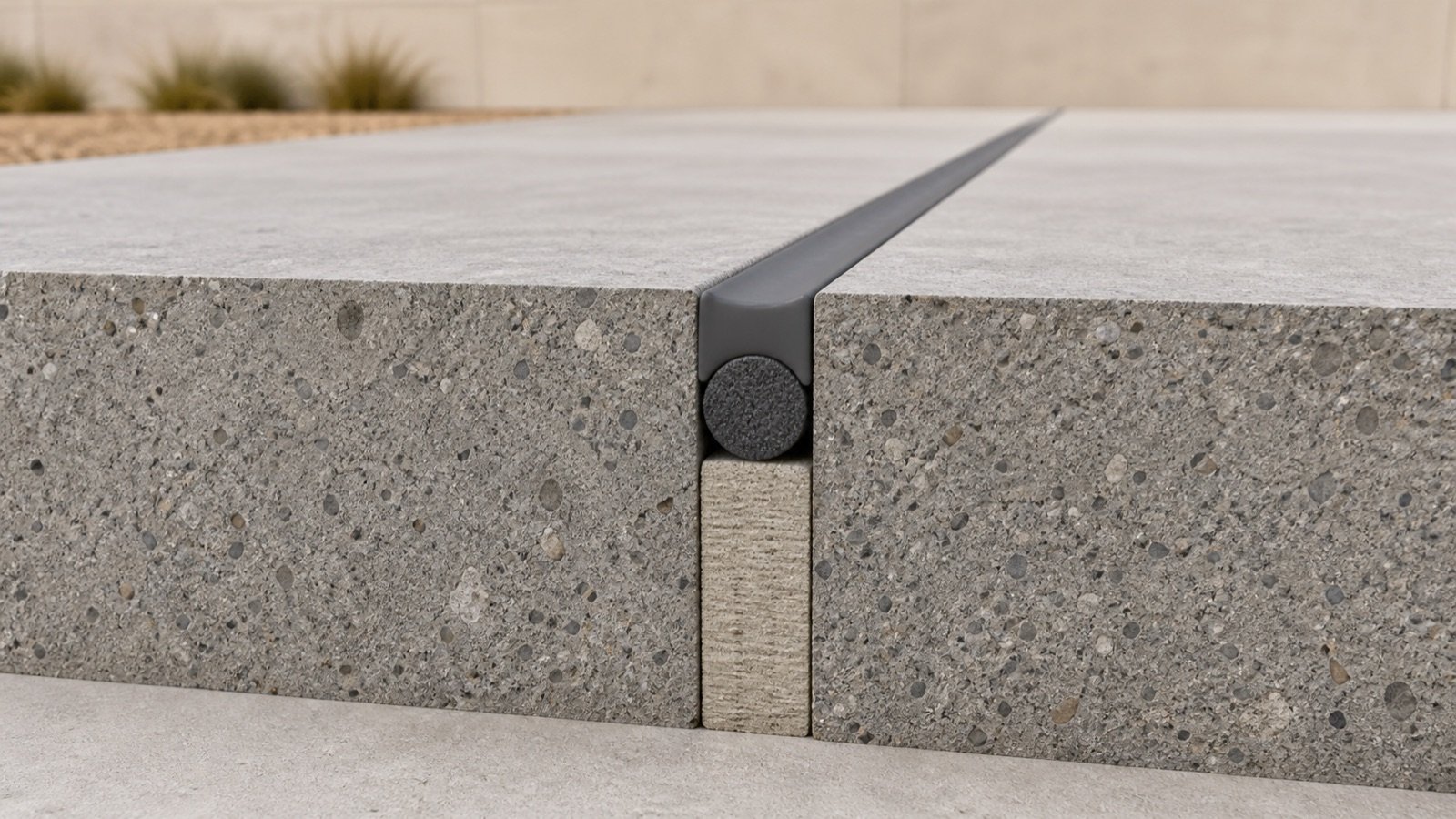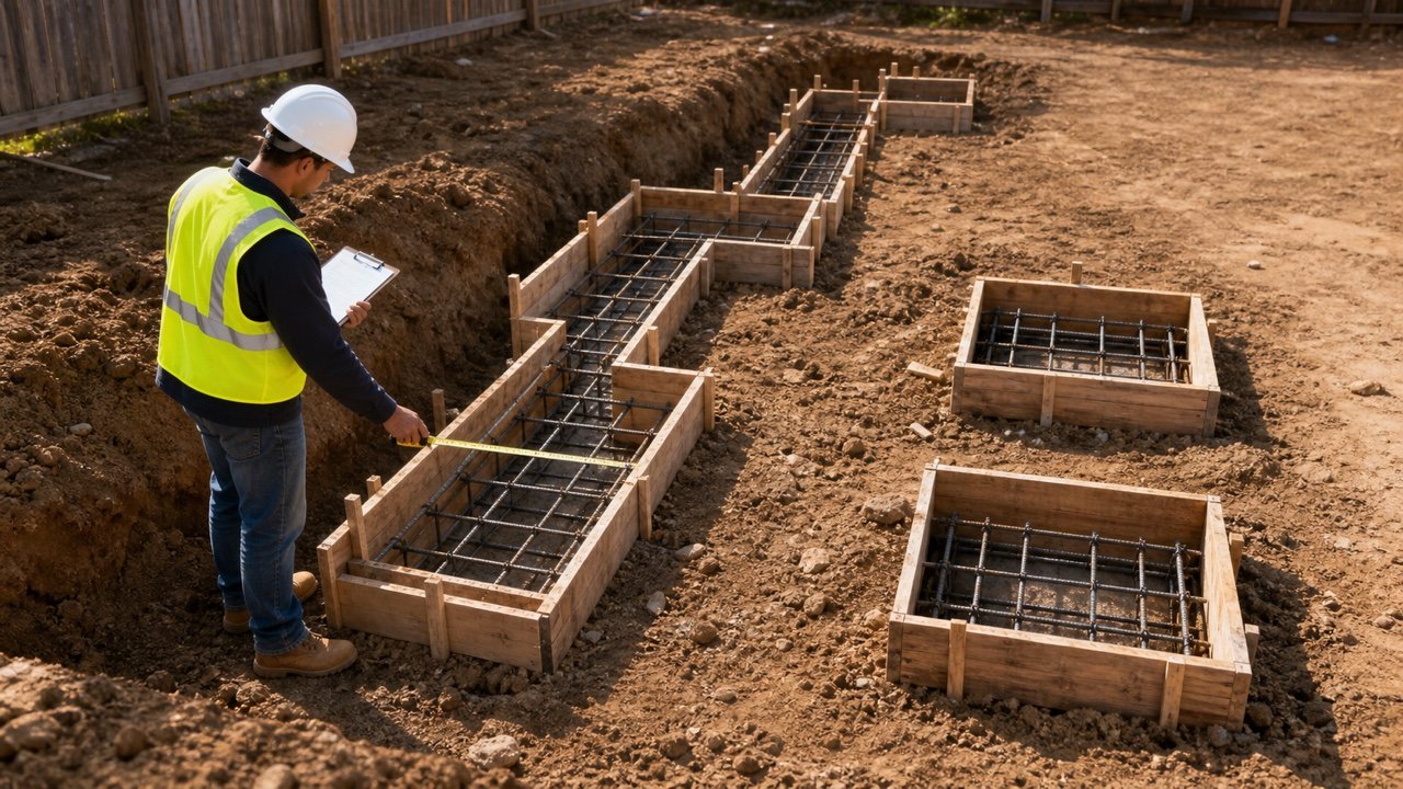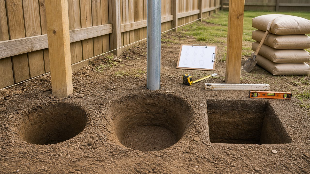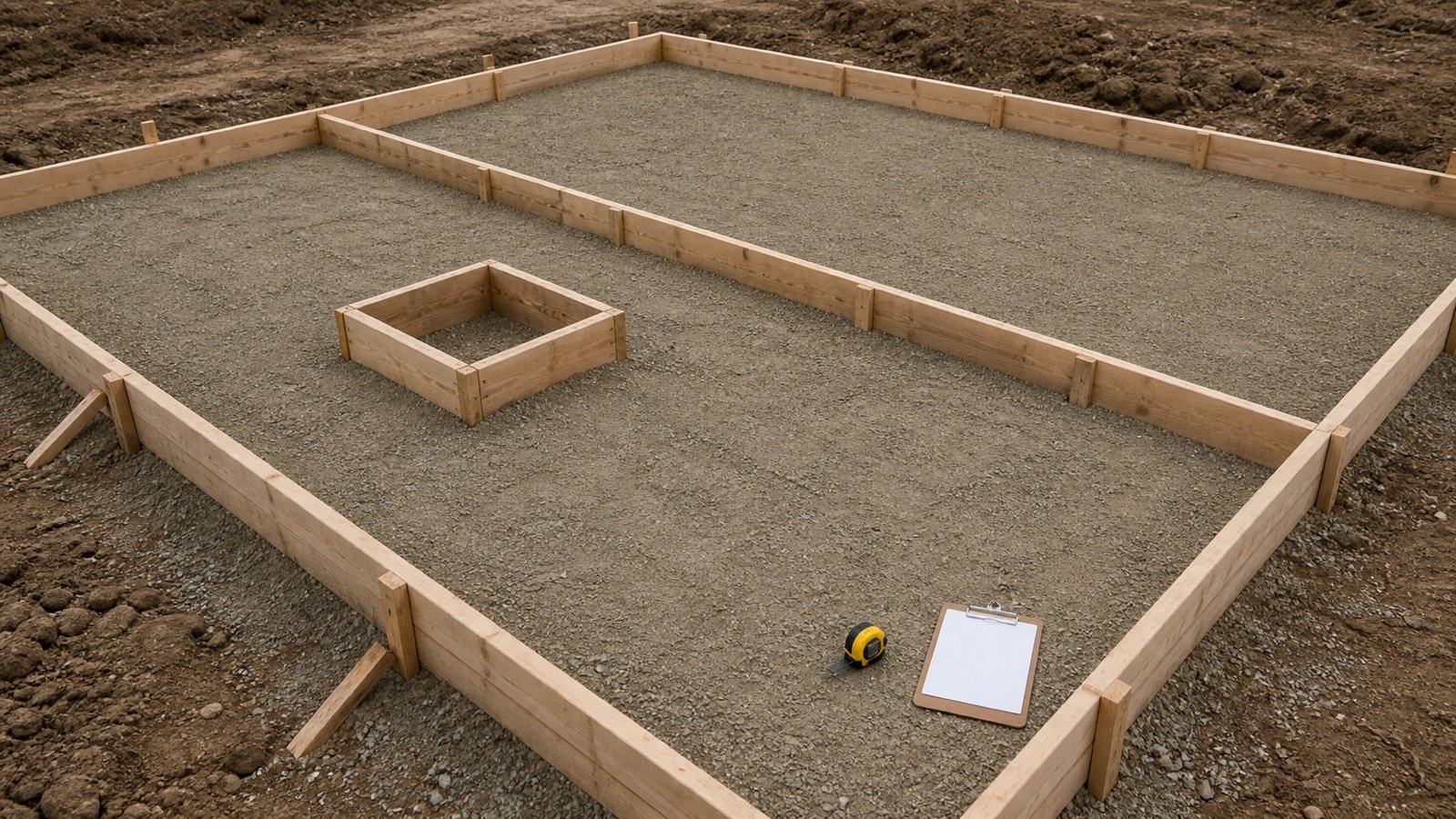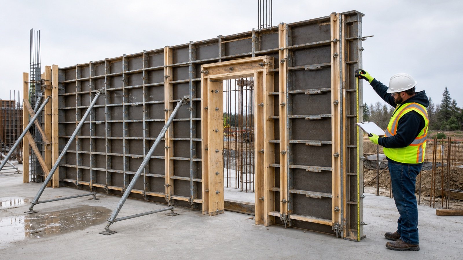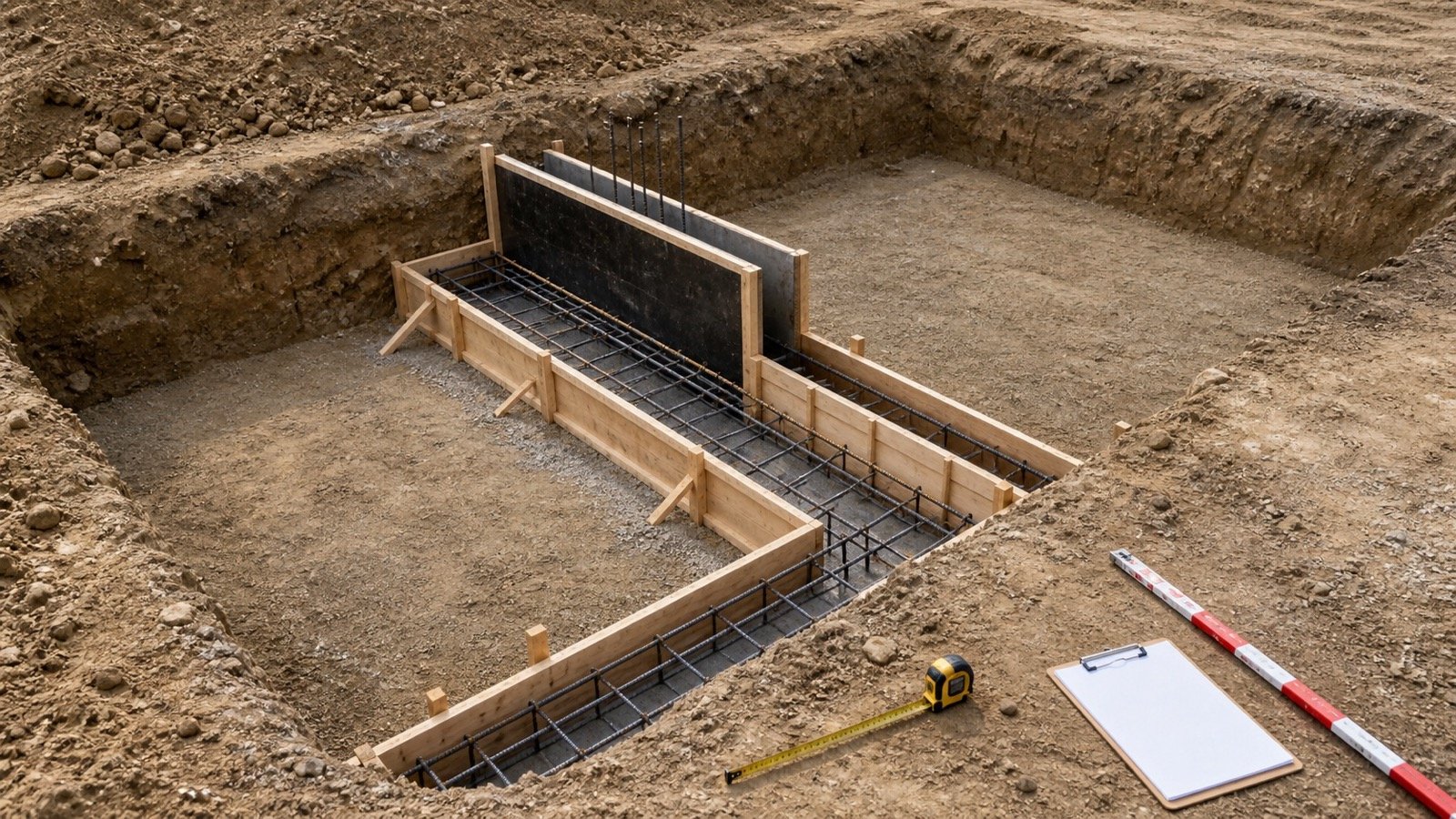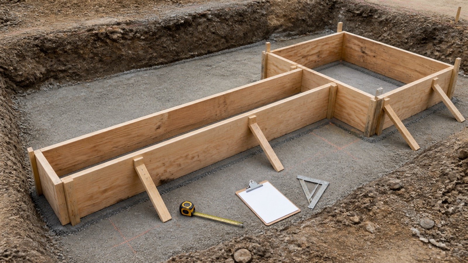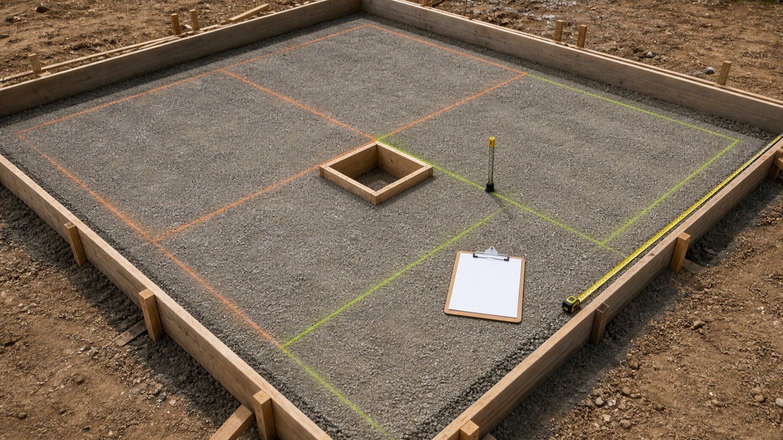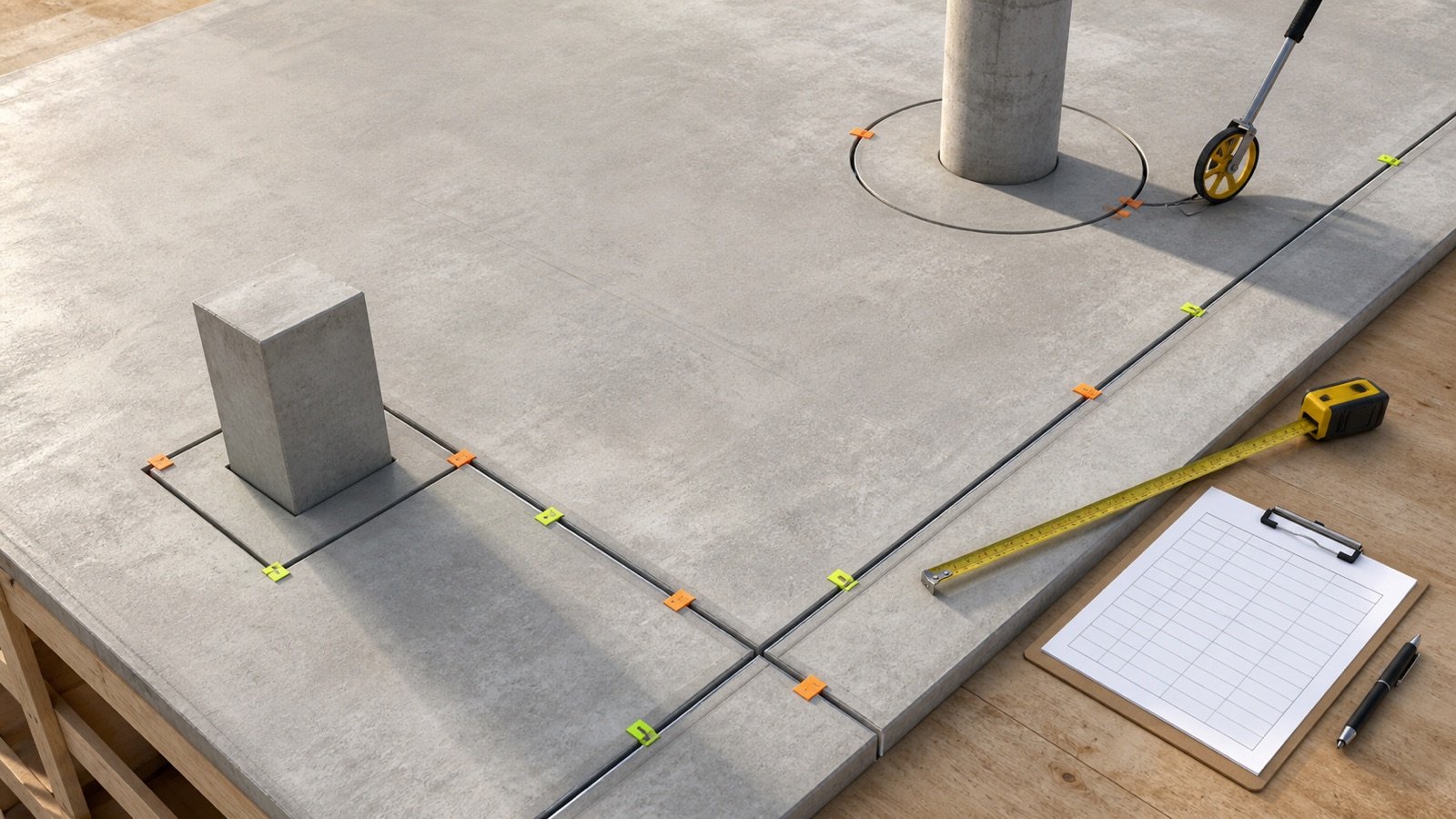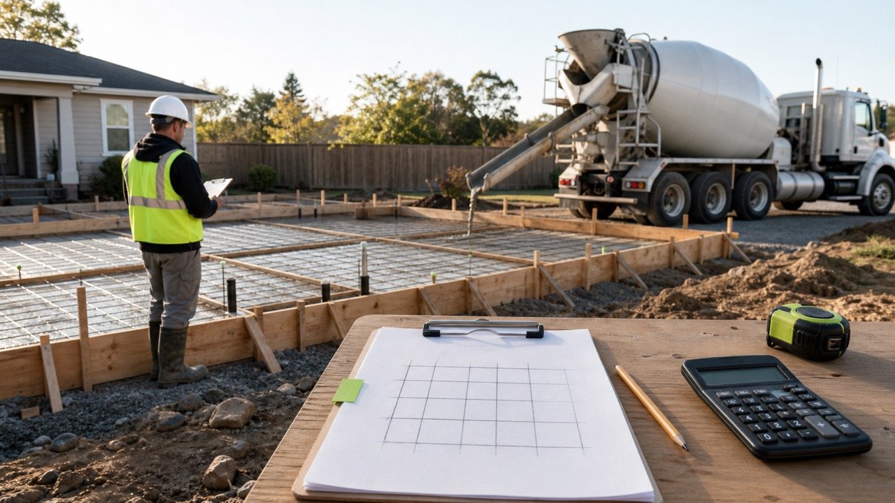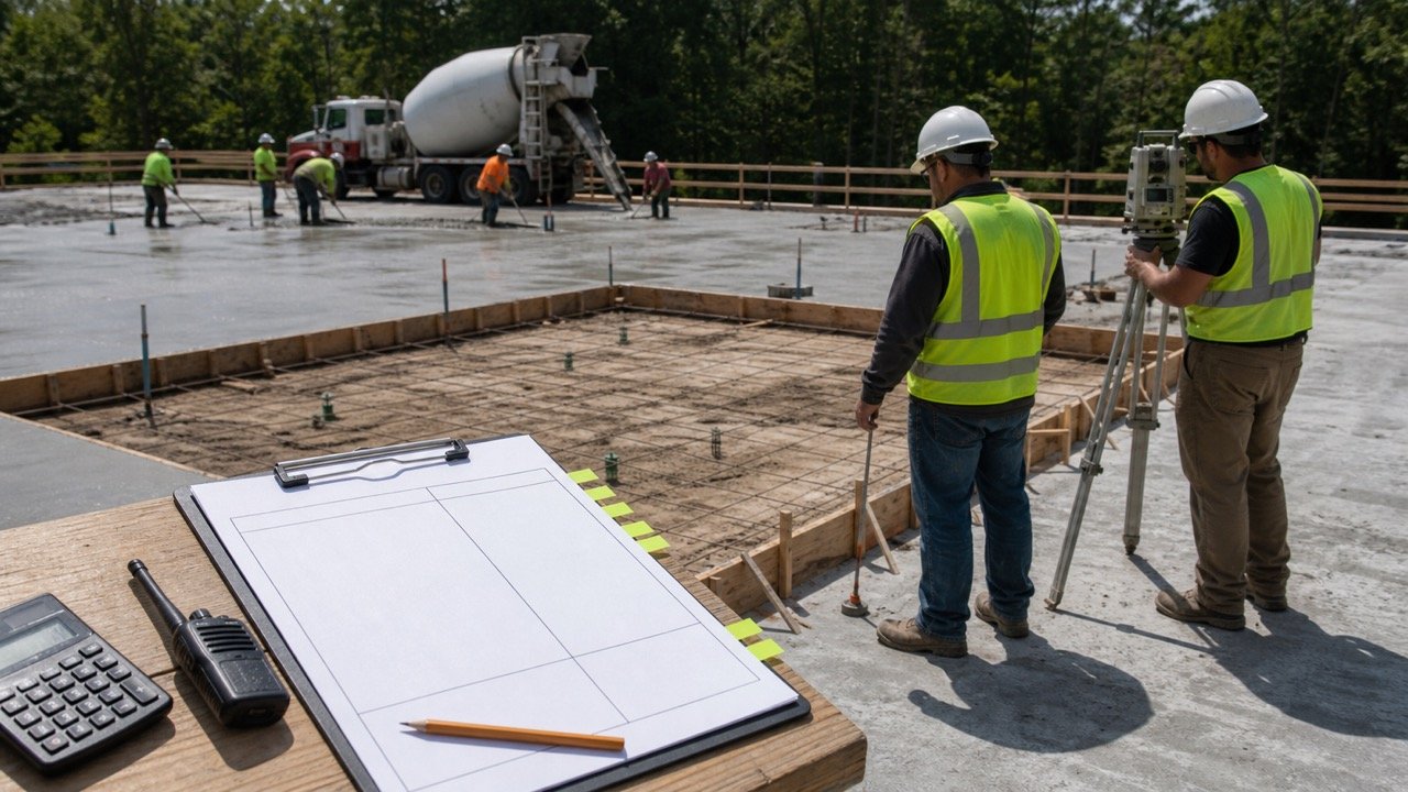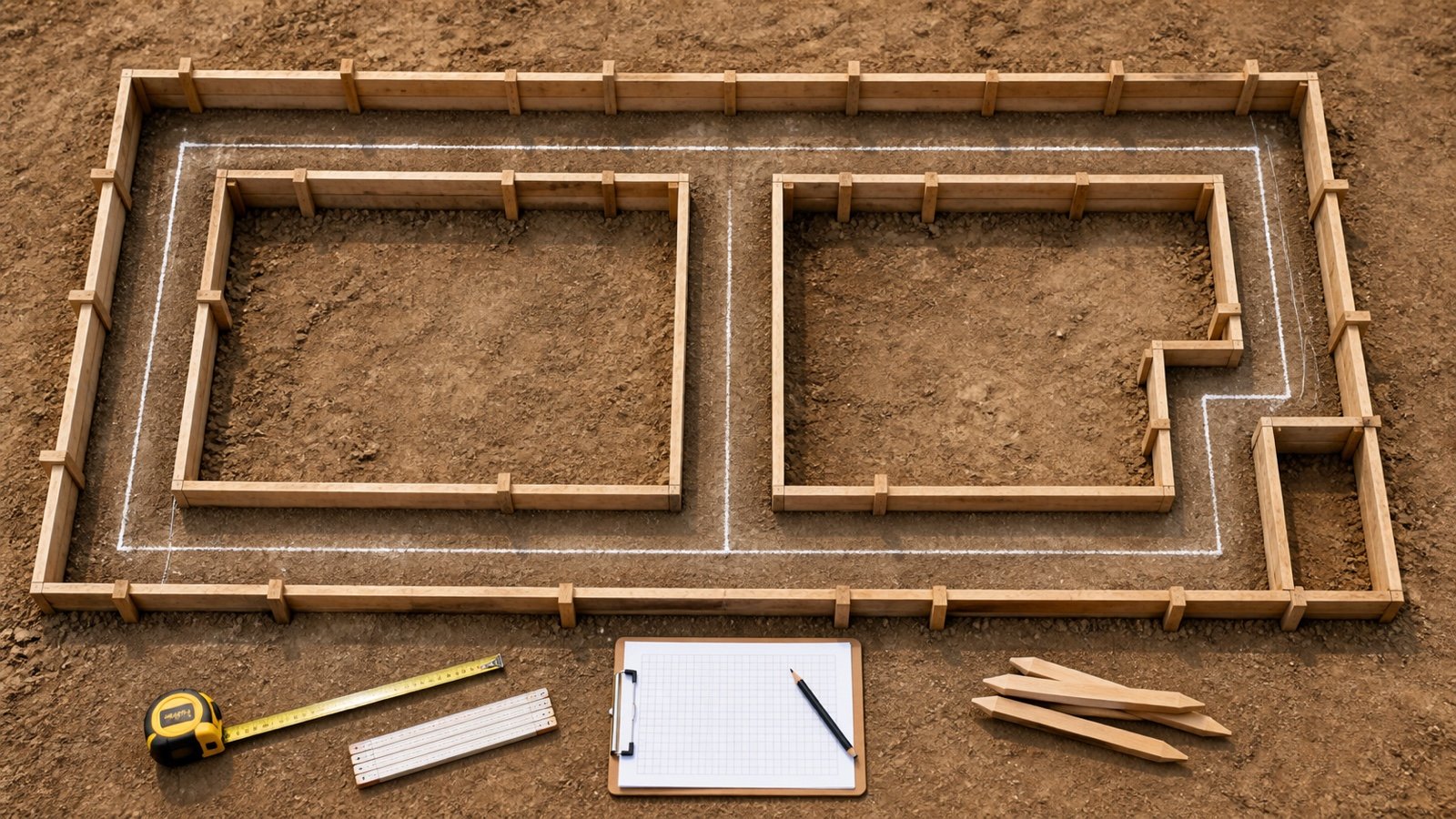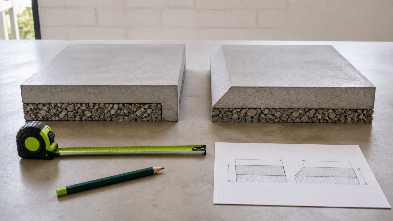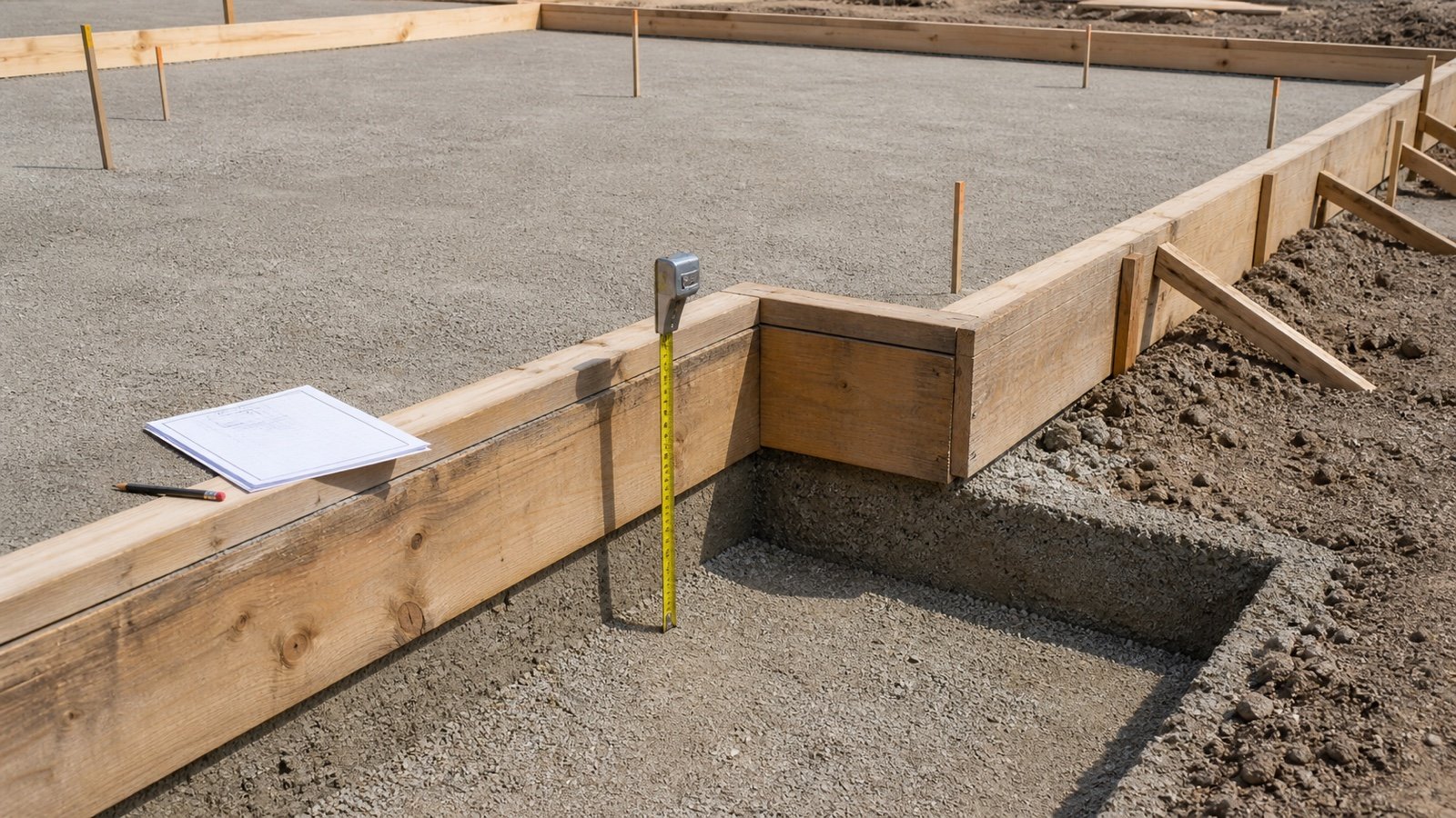
Slab thickness has a direct quantity effect. On a 20 ft by 20 ft plan, each 1 in of added uniform thickness changes the measured volume by 1.234568 yd³.
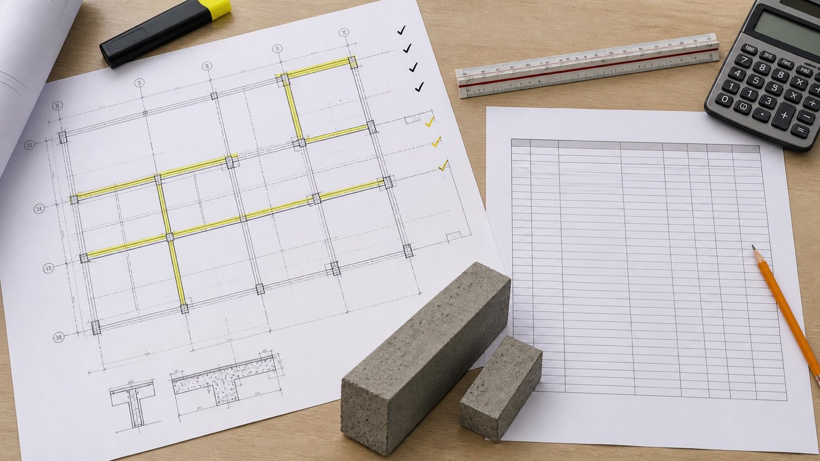
Choose the thickness from the source that governs the work, then identify the exact plan area it covers. One slab outline can contain a uniform field, deeper edges, local pads, ramps and pits.
How thick should a concrete slab be?
Use the thickness stated in the current approved drawings, sections, schedules, notes and specifications for the project. The responsible design, adopted local requirements, loads, soil support, slab type and site conditions determine that value.
ACI 360R-10 addresses several slab-on-ground types, soil-support systems and load categories, including vehicle, concentrated, distributed, line and construction loads. Its scope shows why one patio, driveway or garage table cannot establish a project thickness.
Write the drawing, detail, revision, zone and units beside each thickness used in the quantity takeoff.
Which source should set the slab thickness?
Start with the current accepted project documents. Move to a clarification or investigation when those documents conflict, omit the condition or no longer match the field.
| Source | Use | Check |
|---|---|---|
| Approved drawings and sections | Slab field, edge, beam, pad, pit, ramp and transition depths | Current revision and exact plan extent |
| Schedules, notes and specifications | Element identity, slab type and project requirements | References agree with the plan and details |
| Adopted code and approved design | Requirements within a stated jurisdiction and scope | Edition, amendments and authority having jurisdiction |
| Proprietary-system documents | Requirements for the selected approved system | Exact product, system and current instructions |
| Accepted clarification or revision | Resolves a conflict or changed condition | Issuer, date and affected zone |
| Pre-pour field record | Checks the formed top and prepared bottom boundaries | Method, locations, results and disposition |
| Existing-slab investigation | Checks an unknown built condition | Qualified plan, method limits and safe test locations |
An online thickness chart can help you list questions for the designer, building official or supplier. Keep its number out of the takeoff until an accepted source applies it to the project.
Does the slab type change the design path?
The slab's structural function changes which design information applies. ACI's current technical answer directs a slab-on-ground that transfers vertical or lateral forces from other parts of a building to the soil to ACI 318-19. It directs other slabs-on-ground to ACI 360R-10.
Suspended slabs, post-tensioned slabs, structural mats, pavements, ribbed systems and proprietary assemblies have other geometry and design requirements. Confirm the element before using a thickness in a quantity calculation.
| Question | Why it changes the record |
|---|---|
| Is the slab supported by the ground? | Suspended and ground-supported slabs use different design and construction information |
| Does it transfer building loads to the soil? | The structural design authority can change |
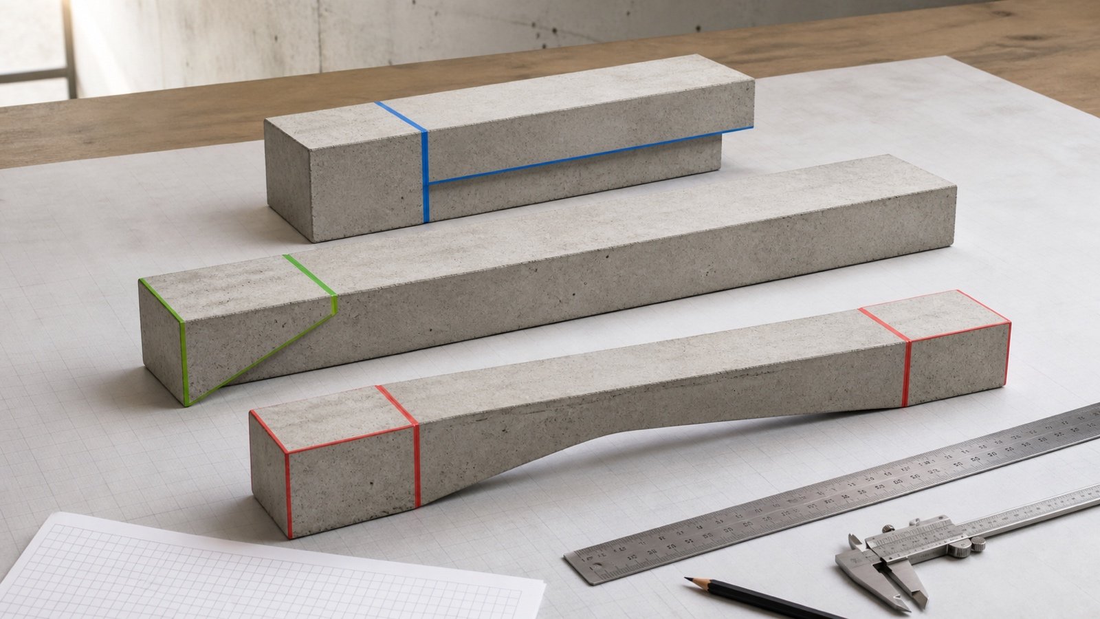
| Is the thickness uniform or variable? | Variable zones need separate boundaries or a verified solid |
| Are edges, beams or ribs integral? | The field thickness does not contain their complete volume |
| Is the slab part of a proprietary system? | The approved system documents can control dimensions and details |
Which top and bottom boundaries define thickness?
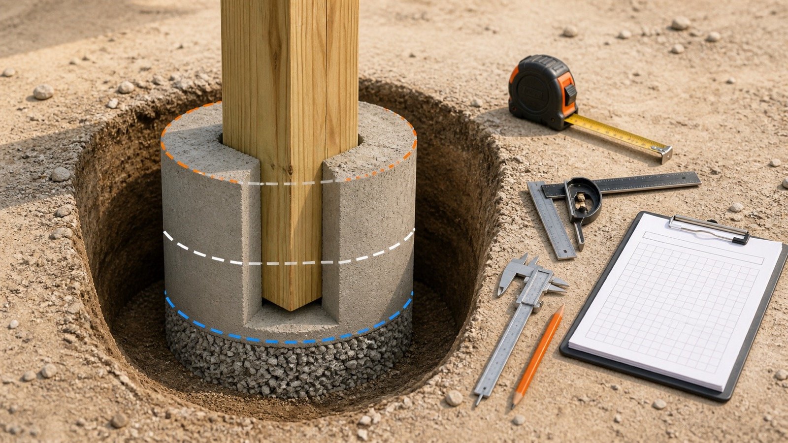
Thickness is the vertical distance between the accepted concrete top and bottom surfaces at the location being measured. Record both boundaries because either one can change.
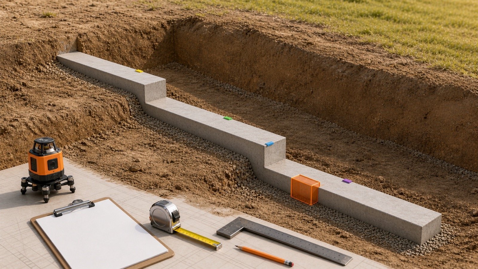
A sloped finished surface over a level base creates changing thickness. A level finished surface over a varying base does the same. A ramp, drain, recess, thickened edge or local pad can change one surface within a small plan area.
After the concrete boundaries are accepted, use the Concrete Slab Formwork Area guide to measure the temporary contact surfaces at edges, blockouts and pour stop ends.
| Field | Record |
|---|---|
| Zone ID | Mark tied to the plan or model |
| Top boundary | Finished elevation, slope, step or accepted reference |
| Bottom boundary | Prepared base, form soffit, void form or accepted reference |
| Thickness | Specified or accepted vertical distance with units |
| Plan extent | Length, width, area, station range or coordinates |
| Source | Drawing, detail, instruction, field record and revision |
| Status | Accepted, changed, pending or excluded with reason |
How should thickness be checked before the pour?
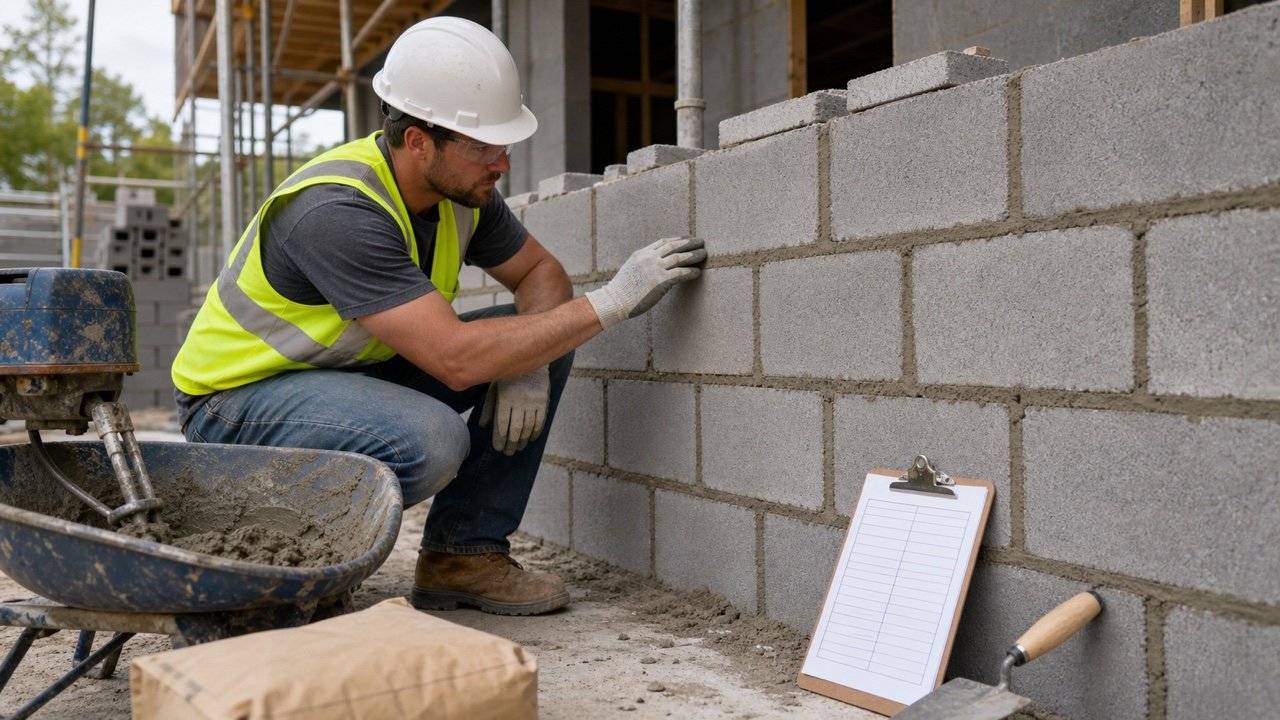
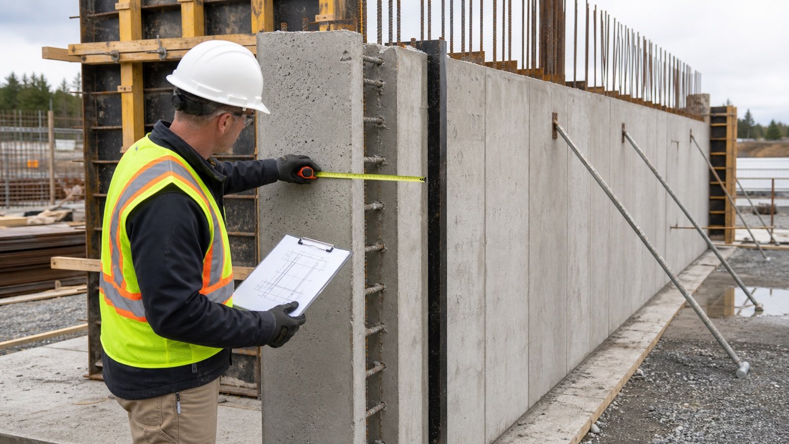
Use the project's inspection and quality process. The check should compare the prepared concrete boundaries with the accepted documents before concrete hides the base and embedded work.
- Confirm the current drawing and detail revisions.
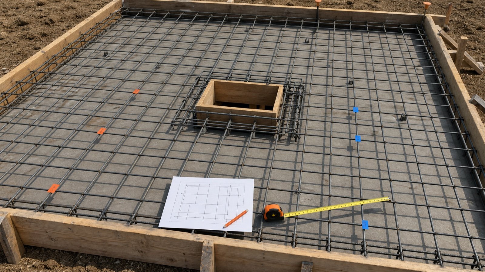
- Mark every uniform field, edge, beam, pad, recess and transition zone on the plan.
- Establish the accepted top references, including slopes and steps.
- Check the prepared bottom boundary, form position and local depth changes at the locations required by the project plan.
- Record the measurement method, point or grid location, result, date and checker.
- Send conflicts and out-of-scope conditions to the responsible party before revising the measured quantity.
- Update the takeoff only from the accepted disposition.
ACI 302.1R-15 lists floor thickness, base and form tolerances, slab-thickness tolerances, and how and when thickness is measured among preconstruction coordination items. It does not supply one tolerance for every project.
Does a form board prove the slab thickness?
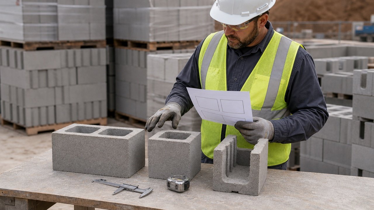
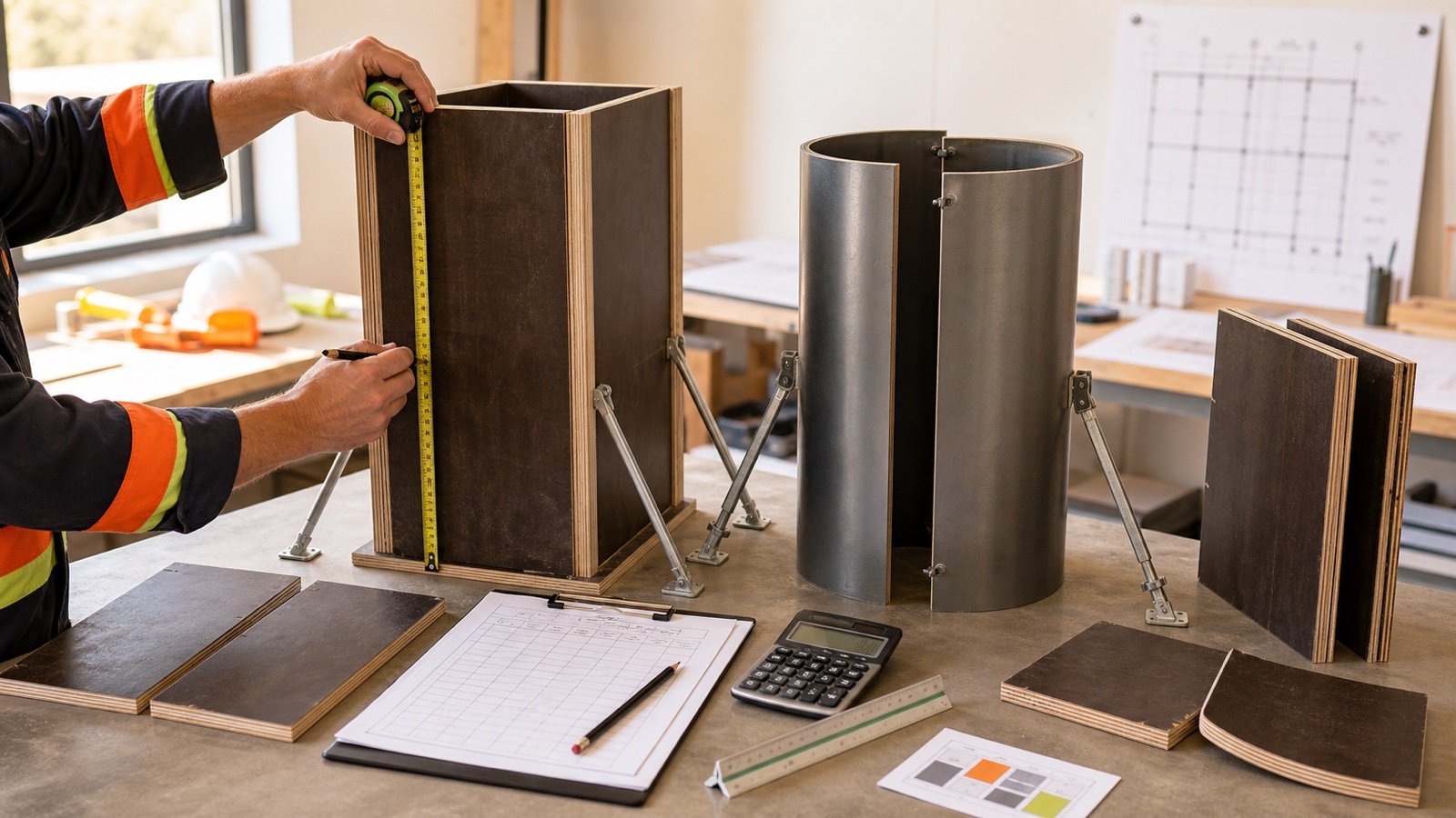
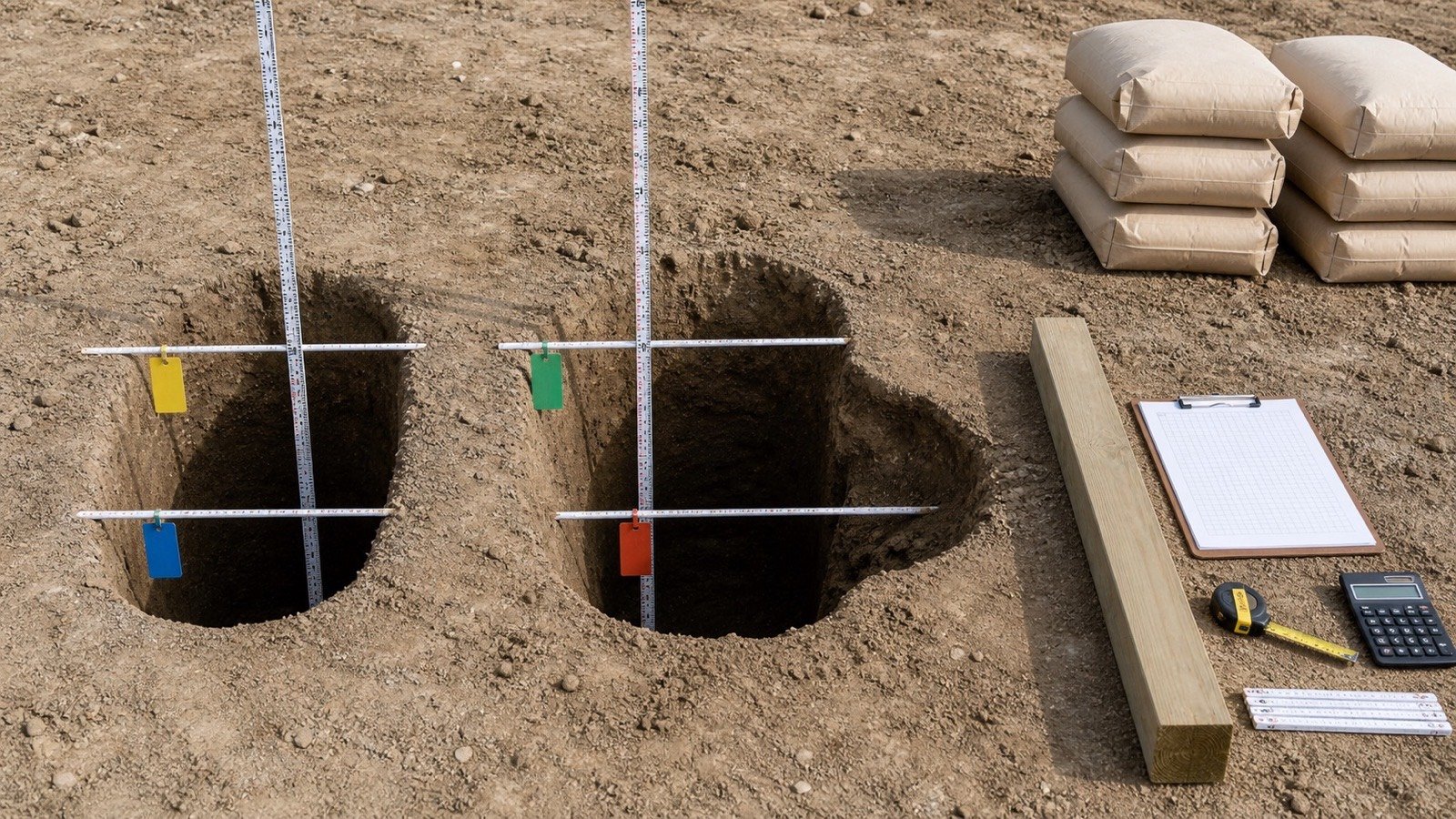
Measure the concrete boundaries. A nominal board name gives a product category, and its physical size can differ from the label. PennDOT LTAP's quantity example notes that its nominal 2-by-4 form is 3.5 in high and tells readers to measure the lumber used for forms.
Board height can still describe only one location. A board may extend below the prepared base, project above a screed reference, sit beside a deeper edge or stop at a slope. Record the accepted top and bottom surfaces instead of copying the board label into every slab zone.
How much does thickness change concrete volume?
Multiply the accepted plan area by the thickness. Use compatible dimensions before multiplication.
Metric volume in m³ = area in m² × thickness in mm ÷ 1,000
Metric volume in litres = area in m² × thickness in mm
Imperial volume in ft³ = area in ft² × thickness in in ÷ 12
Imperial volume in yd³ = area in ft² × thickness in in ÷ 324
Use the Concrete Slab Calculator after the accepted plan dimensions and thickness are known. Keep local thickenings and deductions visible as separate quantity lines.
Imperial thickness comparison for a 20 ft by 20 ft slab
The plan area is 400 ft². The table changes only the uniform thickness and shows measured geometric volume with no allowance.
| Thickness | Cubic feet | Cubic yards | Change from prior row |
|---|---|---|---|
| 4 in | 133.333333 ft³ | 4.938272 yd³ | Starting case |
| 5 in | 166.666667 ft³ | 6.172840 yd³ | +1.234568 yd³ |
| 6 in | 200.000000 ft³ | 7.407407 yd³ | +1.234568 yd³ |
Moving from 4 in to 6 in adds 2.469136 yd³ to this 400 ft² measured slab. The volume rises by 50% because the thickness rises from 4 to 6 in while the plan area stays fixed.
Metric thickness comparison for a 6 m by 4 m slab
This plan has 24 m². Each 10 mm thickness change adds 24 × 10 = 240 L, or 0.240 m³.
| Thickness | Cubic metres | Litres |
|---|---|---|
| 100 mm | 2.400 m³ | 2,400 L |
| 125 mm | 3.000 m³ | 3,000 L |
| 150 mm | 3.600 m³ | 3,600 L |
These rows compare quantity scenarios. They do not recommend a thickness for a 6 m by 4 m slab.
What percentage does 1 extra inch add?
Divide the added thickness by the starting thickness when the plan area stays unchanged. One inch adds 25% to a 4 in section, 20% to a 5 in section and 10% to a 10 in section.
Percentage volume change = thickness change ÷ starting thickness × 100
The cubic-yard change still depends on plan area. For a 400 ft² slab, 0.5 in changes the measured volume by 16.666667 ft³, or 0.617284 yd³.
How should several thickness zones be combined?
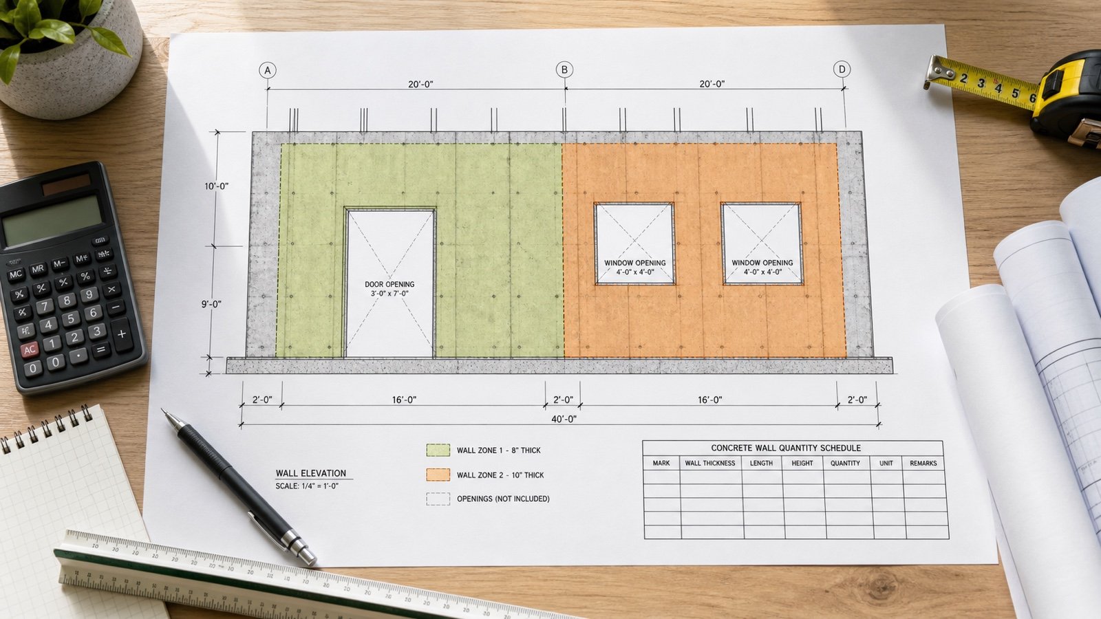
Calculate each non-overlapping zone at its accepted thickness, then add the unrounded zone volumes. Keep the zone IDs and source details beside the total.
Example: one slab plan contains 300 ft² at 4 in and 100 ft² at 5 in.
- Zone A: 300 × 4 ÷ 12 = 100.000000 ft³.
- Zone B: 100 × 5 ÷ 12 = 41.666667 ft³.
- Total: 141.666667 ft³ ÷ 27 = 5.246914 yd³.
The area-weighted summary thickness is (300 × 4 + 100 × 5) ÷ 400 = 4.25 in. It reproduces the total quantity because the 2 verified zones cover the complete plan without overlap. The summary does not replace the 4 in and 5 in requirements on their separate zones.
The Concrete Slab Volume guide shows how to schedule deeper edges, internal thickenings, ramps, openings and partial-depth recesses without counting a solid twice.
How can an existing slab thickness be verified?
Start with records and define why the thickness is needed. A quantity check, anchor assessment, equipment installation, change of use and structural evaluation can need different evidence.
| Evidence or method | Useful for | Main limit |
|---|---|---|
| Approved drawings and as-built records | Initial thickness map and element identity | Records can be missing, superseded or different from the built condition |
| Accessible edge or existing opening | Local screening at one visible point | The point may be a thickened, tapered, worn or repaired zone |
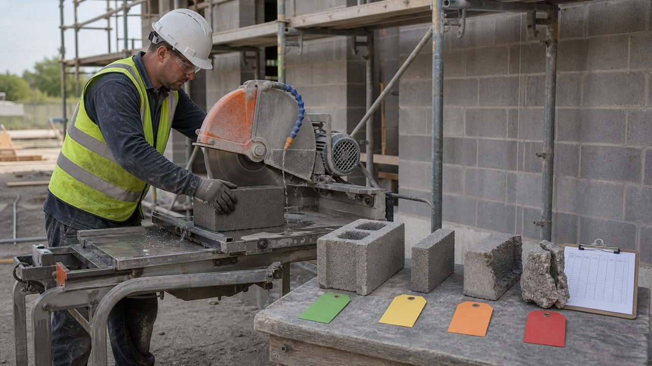
| Concrete core | Direct specimen length at an approved location | Destructive work, location safety, repair and sampling scope require a qualified plan |
| Impact-echo or ground-penetrating radar | Nondestructive investigation under a suitable procedure | Equipment, calibration, material conditions, access and interpretation affect results |
| Laser or elevation survey method | Thickness study where the required surfaces and reference data are available | Surface access and method design control what can be established |
ACI's 2022 slab-on-ground study compared core, impact-echo, laser-scanning and ground-penetrating-radar thickness data. ASTM C1542/C1542M-19 gives public scope for measuring drilled core length and excludes adhered particles that are not part of the concrete mixture.
A qualified investigation plan should select test locations, check for post-tensioning, reinforcement, embedded services and structural risks, set the required precision, and define how results will be interpreted. Do not drill or cut an unknown slab to answer a quantity question.
When does a visible edge give the wrong impression?
An edge reading describes that location. The slab can have a thickened perimeter, turned-down edge, local taper, overlay, worn surface, buried base, repair or different interior depth.
Record the edge location and visible layers. Use it as one item of evidence, then compare it with the plan, sections and any approved investigation results before applying it to the full area.
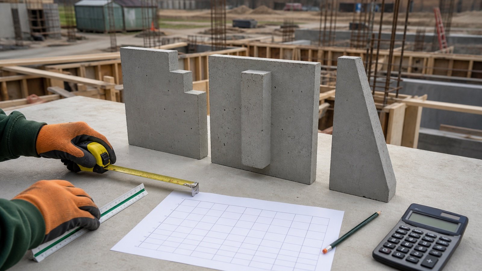
Which conditions need a separate thickness zone?
| Condition | Quantity treatment |
|---|---|
| Uniform field with a sharp depth step | Separate non-overlapping constant-thickness zones |
| Square-edged perimeter thickening | Base slab plus the verified extra edge depth |
| Sloped surface with verified planar faces | Accepted wedge or average-depth solid for that boundary |
| Integral beam, rib or strip | Separate cross-section and length record |
| Pad above the slab | Add only the volume above the base slab already counted |
| Pit, recess or opening | Record the concrete retained and removed at each depth |
| Unknown or irregular bottom surface | Field measurement or accepted adjustment method before final quantity |
Which thickness mistakes change the takeoff?
- Choosing a value from a generic project-type table without an accepted project source.
- Using one thickness for every zone on a slab with edges, beams, pads, pits or ramps.
- Reading a nominal board name as its physical dimension.
- Using form height when the accepted concrete boundaries differ.
- Applying one exposed-edge reading to the complete existing slab.
- Combining a structural slab, suspended slab and slab-on-ground under one rule.
- Averaging unlocated field readings without an accepted sampling method.
- Turning a measured thickness difference into an automatic waste allowance.
- Rounding thickness or zone volume before the final total.
- Using added concrete quantity as proof that the revised section is structurally adequate.
What should the thickness record contain?
- Project, slab mark, location, purpose, date and preparer.
- Slab type and structural function.
- Drawing, section, detail, note, specification and revision.
- Zone ID, plan extent, top boundary, bottom boundary, thickness and units.
- Form, base, screed, elevation and local-thickening checks required by the project.
- Field measurement point, method, result, checker and disposition.
- Unresolved conflicts and the responsible party asked to resolve them.
- Measured volume, thickness sensitivity and any later accepted quantity revision.
Keep reinforcement decisions in their own record. The slab rebar measurement guide covers approved bar zones, layers, spacing, openings and laps.
What design and safety limits apply?
This guide does not design a slab or set its thickness, loads, soil support, reinforcement, joints, concrete properties, drainage, frost protection, vapour control, insulation, formwork, tolerances or test plan. Current project documents, adopted requirements, field evidence and qualified professionals control those decisions.
Existing-slab drilling, cutting and scanning need permission, utility and embed checks, equipment controls, access planning and a repair method. Wet portland cement can cause cement burns and dermatitis. Follow applicable safety requirements, product information and the project's controls.
After thickness and plan zones are accepted, use the Concrete Slab Calculator for measured volume. Use the Ready-Mix Concrete Calculator only after the geometry is checked and the order assumptions are documented. Return to the Concrete Planning hub for related tools and guides.
Sources and source scope
- ACI 360R-10 preview, Guide to Design of Slabs-on-Ground: slab types, soil-support systems, loads, joints and design-method scope.
- ACI technical answer on slab-on-ground design: the ACI 318 and ACI 360R design-path distinction stated above.
- ACI 302.1R-15 preview, Guide to Concrete Floor and Slab Construction: preconstruction coordination of floor thickness, base and form tolerances, slab-thickness tolerances, and measurement timing and method.
- ACI, Slab-on-Ground Thickness Measurement: the named core and nondestructive methods studied under its stated scope.
- ASTM C1542/C1542M-19 public scope: drilled concrete-core length measurement.
- PennDOT LTAP, Estimating Concrete Amounts: compatible dimensions, area × thickness volume, cubic-yard conversion and actual form measurement.
- NIST Handbook 133 (2026), Appendix E: unit relationships used in the metric and imperial fixtures.
- OSHA concrete-products hazard guidance: concrete-construction and wet-cement skin-hazard context for covered U.S. work.
Source scope: ACI supports the design and coordination boundaries and identifies studied thickness-measurement methods. ASTM supports the stated core-length scope. PennDOT and NIST support the quantity arithmetic and units. OSHA supports the cited U.S. hazard context. These sources do not approve a project thickness, field change, tolerance, test plan, structural capacity, allowance or supplier order.
The calculation methodology explains unit conversion, precision, assumptions and corrections.
Review note: Saleem Sial owns the research and editorial record. Arithmetic fixtures, source checks, build validation and rendered QA form the internal publication gate. Waseem Sial, External Reviewer and Engineer, is listed for ongoing external review; no completed review date is claimed.