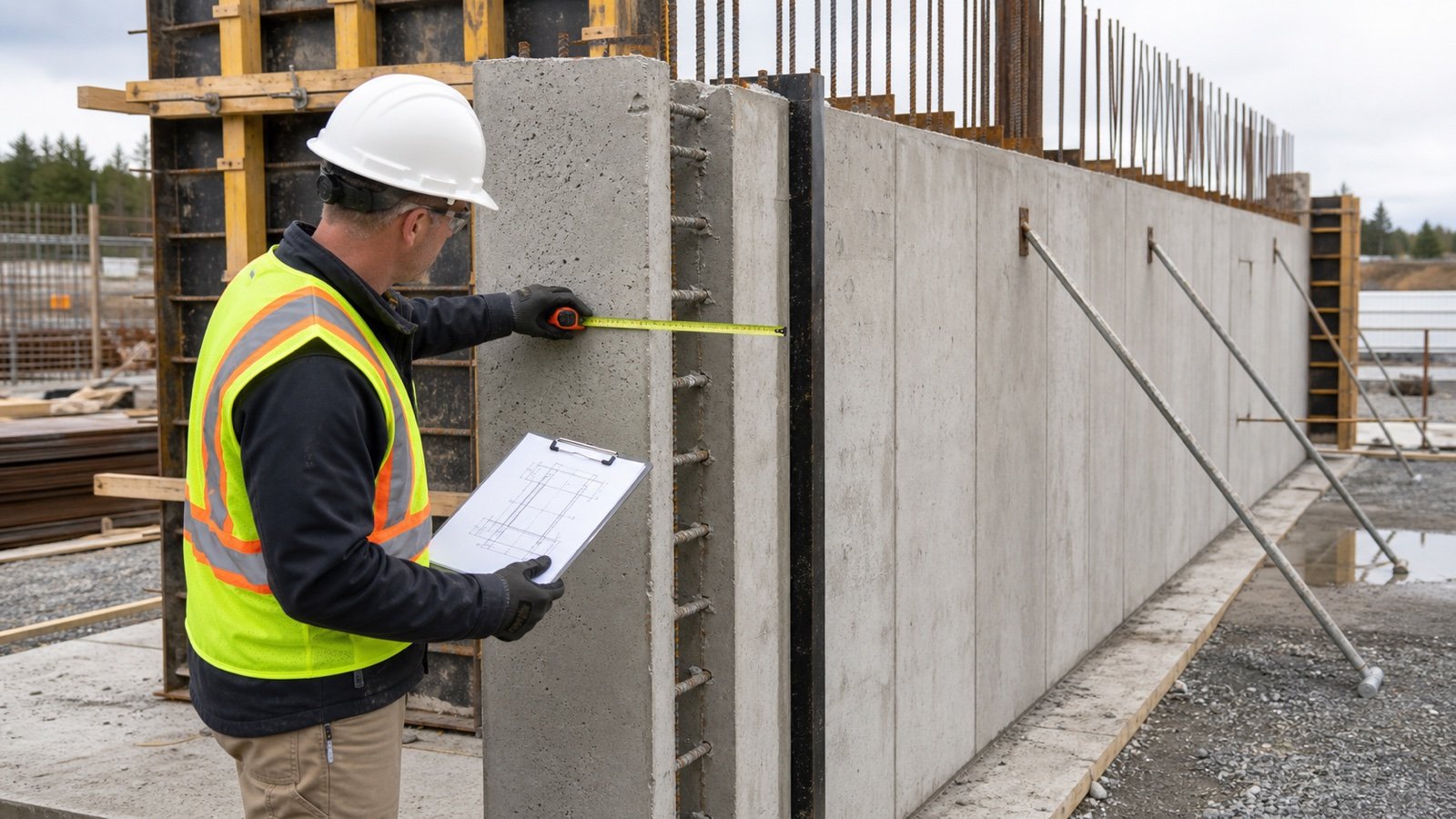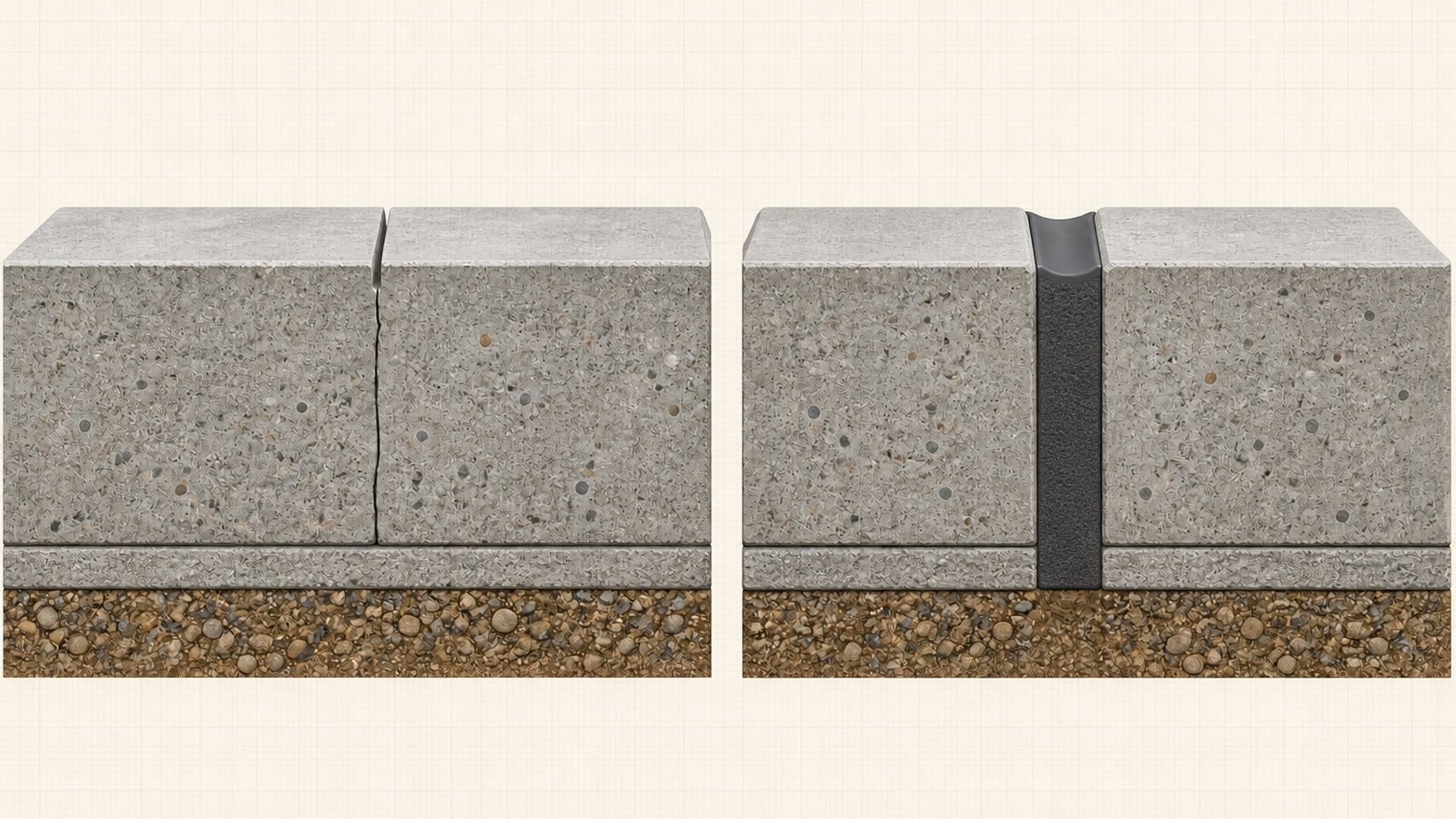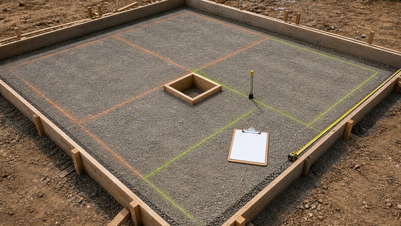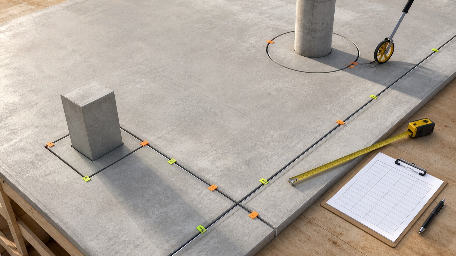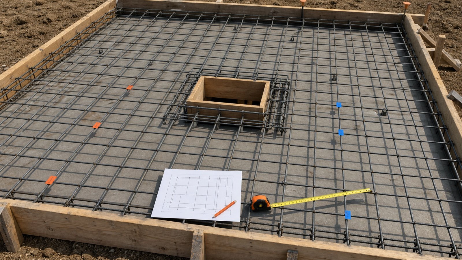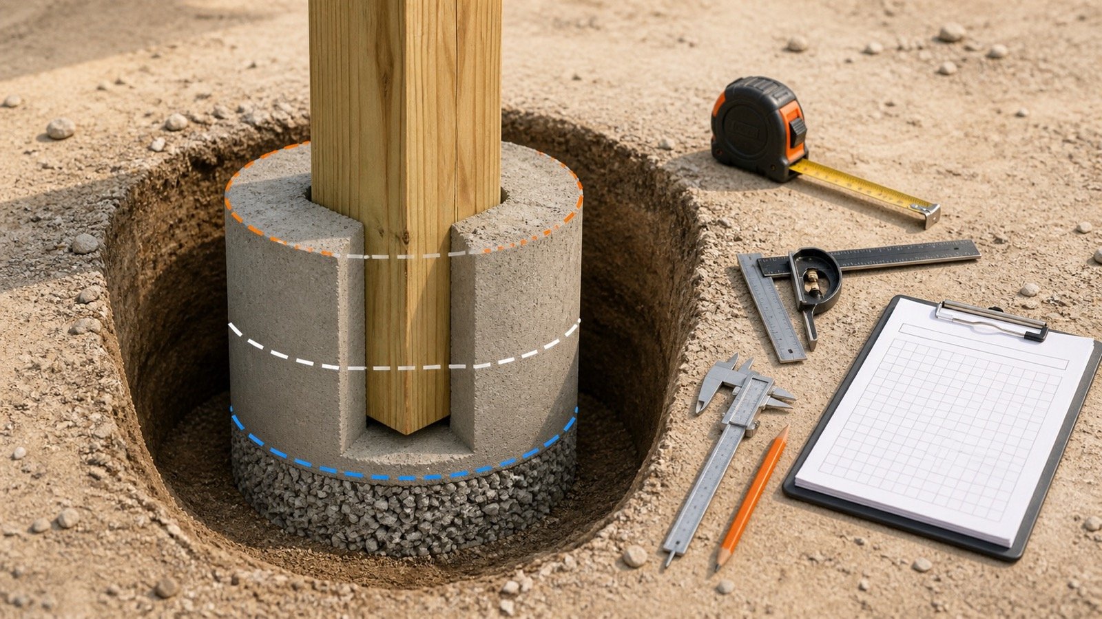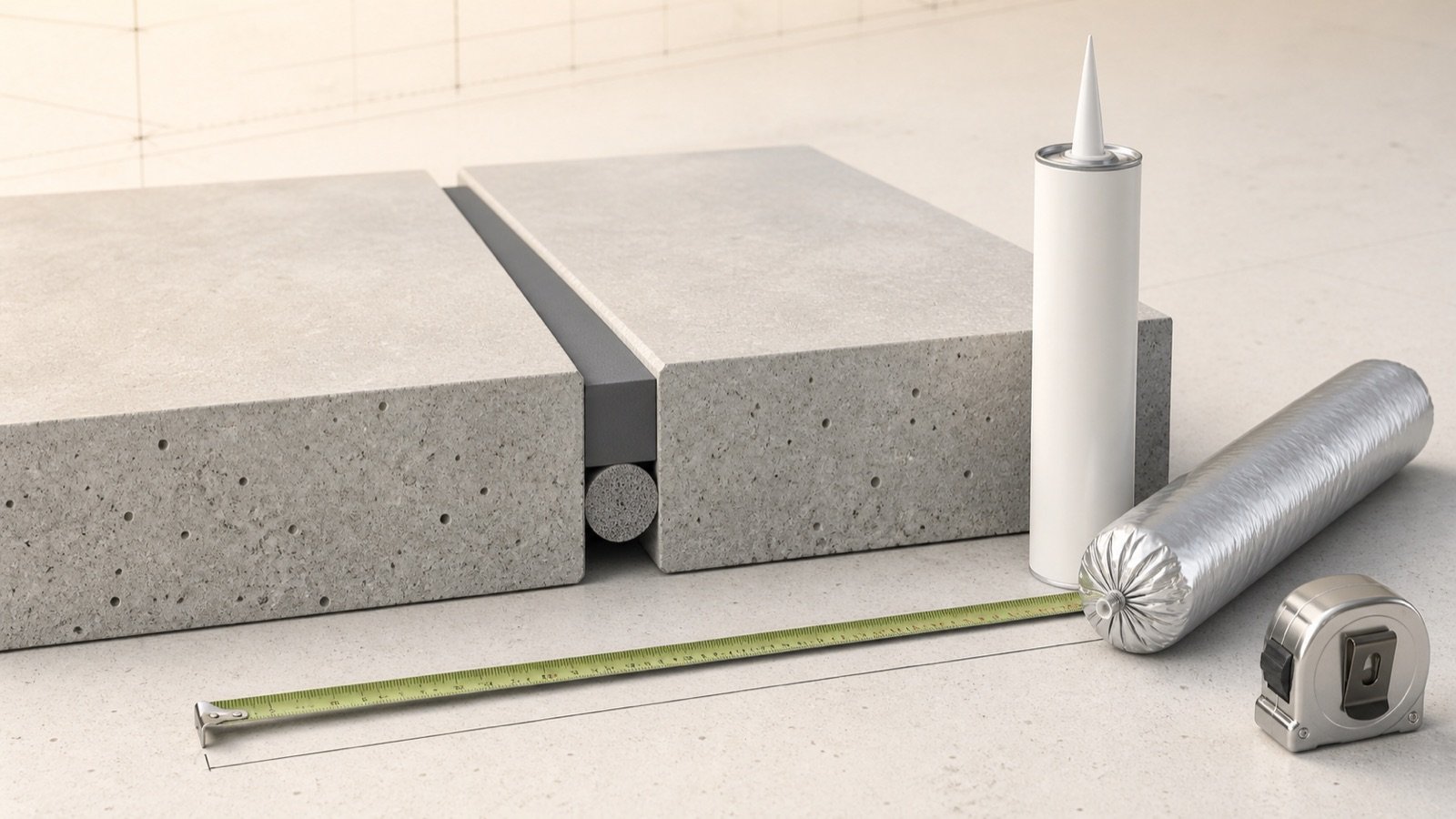
A concrete expansion-joint detail can contain several materials in one narrow opening. Preformed filler separates the concrete sections, backer rod or tape controls the sealant reservoir, and field-applied sealant protects the top of the joint.
Read the detail as a material system. Record each component, installed dimension, product standard, exposure and purchasing unit before calculating a quantity or starting a repair.
Which materials go into a concrete expansion joint?
A sealed concrete isolation or expansion joint commonly has compressible filler through most of the separation, a recessed backer rod or bond breaker, and a flexible sealant at the exposed face. The project can also require primer, edge protection, a waterstop, a cover or a load-transfer assembly.
ACI CT-25 defines joint filler as compressible material that fills a joint, blocks debris and supports applied sealant. It defines joint sealant as compressible material that excludes water and solid foreign material. Those terms describe different jobs inside the joint.
| Component | Position and function | Takeoff basis | Required evidence |
|---|---|---|---|
| Preformed joint filler | Occupies the full-depth separation below the sealant reservoir and remains compressible | Joint length, filler height, thickness, sheet or roll layout | Joint detail, filler schedule and product data |
| Backer rod | Sits below field sealant, controls sealant depth and prevents bonding to the reservoir bottom | Joint length and approved nominal rod size | Sealant instructions, rod type and compatibility |
| Bond-breaker tape | Covers the reservoir bottom where the approved system uses tape in place of rod | Joint length and tape width | Sealant data and joint geometry |
| Primer | Prepares specified joint faces for the selected sealant | Surface area or product coverage | Substrate, exposure, product instructions and test requirements |
| Field-applied sealant | Adheres to the 2 joint faces and closes the exposed reservoir | Installed length × width × depth, then product yield | Approved sealant profile, product data and package size |
| System components | May continue waterproofing, fire rating, traffic protection or movement through another assembly | System-specific length, area or count | Architectural, structural and manufacturer details |
Some projects use a preformed compression seal instead of a liquid sealant and backer rod. FHWA describes compression seals as preformed products that remain compressed against the reservoir sidewalls. Measure that system under its own approved size and installation rules.
How do the layers work together?
The full-depth filler preserves the separation while the adjoining concrete is placed. The installer removes or recesses the filler at the top when the detail calls for a sealant reservoir, then installs backing and sealant at the specified depth.
The ACPA pavement bulletin shows this sequence for isolation and expansion joints: preformed filler occupies the joint face, part of the filler is removed at the top, closed-cell rod sits in the reservoir, and formed-in-place sealant finishes the exposed section. W. R. Meadows publishes a comparable arrangement for one ASTM D1751 fibre filler product.
The featured image shows that general stack. It does not set the reservoir depth, bead profile, filler thickness, rod size or recess. Those values come from the current project and selected system.
Which preformed filler types can a specification name?
ASTM public scope pages separate bituminous and elastomeric filler families. A product needs its own current compliance evidence; a material name alone does not prove that it meets a project specification.
| Reference | Material family in the public scope | What to check on the product |
|---|---|---|
| ASTM D1751 | Nonextruding, resilient bituminous preformed filler | Current standard edition, stated compliance, thickness, height, recovery, extrusion and exposure limits |
| ASTM D1752 Type I | Preformed sponge rubber | Type designation, size, property data and approved construction use |
| ASTM D1752 Types II and III | Cork and self-expanding cork | Exact type, expansion condition, storage and installation instructions |
| ASTM D1752 Type IV | Recycled PVC | Type designation, dimensions and stated compliance |
| Project-specific foam or other filler | Material named by the contract documents | Applicable standard, compressibility, recovery, absorption, chemical exposure and sealant compatibility |
Filler thickness matches the designed joint separation, while filler height follows the slab or structural detail and the required sealant reservoir. Sheet length, roll length, strip width and available thicknesses affect cutting and ordering.
Do not replace one filler family with another based on color or stiffness. Send substitutions through the project's approval process with the current technical data, standard designation and effect on the rest of the joint system.
Is backer rod the same as expansion-joint filler?
Backer rod and full-depth joint filler occupy different parts of the common sealed detail. Backer rod is a compressible round or shaped backing inside the sealant reservoir. Preformed filler separates the concrete below that reservoir.
FHWA describes rod as a material that helps set the sealant shape factor and prevent three-sided adhesion. ACI's filler definition covers the larger compressible material that fills the joint, limits debris entry and supports sealant. A repair can expose one component, both components or a different system.
Do not assume that a new rod replaces deteriorated full-depth filler. Confirm whether the remaining material still preserves the designed separation, whether removal could disturb the joint, and which repair detail applies.
Which backer rod type should you use?
Use the type and nominal size approved by the sealant manufacturer and project specification. Closed-cell, open-cell and hybrid rods differ in compressibility, moisture behavior, surface condition and installation response.
| Rod type | Useful product question | Condition to verify |
|---|---|---|
| Closed-cell foam | Does the selected sealant allow this foam and sizing method? | Water exposure, puncture risk, compression, application temperature and outgassing guidance |
| Open-cell foam | Does the sealant cure mechanism and detail allow a permeable backing? | Tremco warns against open-cell rod in flat joints where water can pond and wick below the sealant |
| Hybrid or bicellular foam | Does the product combine a closed exterior with a softer open-cell core? | Approved compression, compatibility and exposure |
| Bond-breaker tape | Does the selected sealant permit tape when the reservoir is too shallow for rod? | Full bottom coverage, tape width and sidewall adhesion area |
Sizing instructions vary. Sika's current 411 page says its closed-cell rod is typically up to 25% larger than the joint width. ACPA's pavement bulletin gives about 25% to 50% for its stated pavement work. Another Sika rod page uses an added 1/8 in for its named 3/4 in product. Record the instruction that belongs to the selected rod, sealant and application.
Install rod without puncturing or stretching it. ACPA advises a compatible rod placed uniformly to the required depth; its pavement guidance also keeps rod continuous through intersections. Manufacturer instructions control the project procedure.
Why should sealant bond to 2 sides?
A field-applied movement seal normally bonds to the 2 opposing joint faces. Backer rod or approved tape prevents a third bond at the bottom, leaving the bead free to change shape as the joint opens and closes.
FHWA links three-sided adhesion and the wrong shape factor with higher sealant stress. Rod depth, reservoir width and product instructions establish the installed bead dimensions. A deeper bead does not automatically produce a better seal.
Sealant that touches the full-depth filler can still require an approved bond-breaker layer. W. R. Meadows tells users of one fibre filler and named cold-applied sealants to isolate the filler from the sealant with its cap, rod or tape arrangement. Other products can specify a different detail.
How do self-leveling and non-sag sealants differ?
Self-leveling material flows into a prepared horizontal reservoir. Non-sag or toolable material retains its shape on vertical, sloped or other surfaces covered by its product data.
Sika limits its current 411 self-leveling product to horizontal use and says it is not for sloped surfaces. QUIKRETE likewise separates a self-leveling horizontal product from a non-sag vertical product in its repair guide. These examples show why the installation orientation belongs in the product check.
Chemistry alone does not select the sealant. Record anticipated movement, substrate, horizontal or vertical position, traffic, water or fuel exposure, ultraviolet exposure, application temperature, primer, cure time, reopening time, color and compatibility with filler, rod, coatings and membranes.
When are primer and bond-breaker tape required?
The selected sealant data decides. Some substrates or exposure conditions require primer, while another combination can use a documented primerless procedure after an adhesion check.
Bond-breaker tape can replace rod where the reservoir is too shallow for the allowed rod and the sealant instructions approve tape. It must cover the bottom without reducing the required sidewall bonding area.
Keep primer and cleaner quantities separate from sealant volume. Their coverage depends on substrate porosity, joint-face area, application method, package size and shelf-life rules.
What should you record from the product data sheet?
Use the current technical data sheet, safety data sheet and project specification for the exact market and product revision. A retailer description or familiar brand name leaves too many installation variables unresolved.
| Record | Why it changes the work or quantity |
|---|---|
| Approved joint and substrate types | Concrete, asphalt, metal, coating and membrane interfaces can need different preparation or products |
| Movement capability and designed profile | Joint width and bead depth must suit the approved movement and product limits |
| Horizontal, vertical, sloped or traffic use | Flow, tooling, recess and reopening requirements differ |
| Backing and bond-breaker instructions | Rod type, size, compression and insertion depth control the reservoir |
| Primer and surface preparation | Dust, laitance, moisture, old sealant and curing compounds can interfere with adhesion |
| Application and service temperatures | Product flow, cure, backing compatibility and timing can change |
| Package volume and coverage table | Whole-package count must use the purchased product's usable coverage |
| Cure, traffic and immersion limits | The crew needs a protected time window before exposure |
| Safety and disposal documents | PPE, ventilation, chemical handling and waste rules come from the current SDS and site plan |
How should you group the material takeoff?
Make one line item for each unchanged combination of joint type, width, sealant depth, filler size, rod or tape, primer, sealant, exposure and package. Split the measured route as soon as one of those fields changes.
- Trace each joint run to its detail and material schedule.
- Measure length along the joint centerline and deduct excluded openings only when the documents require it.
- Group equal cross-sections and systems.
- Record filler in length plus height and thickness; record rod by length and nominal size.
- Calculate sealant from the approved installed width and depth, then use the current package yield.
- Add a documented allowance once and keep whole-package rounding visible.
- List primers, cleaners, caps, tapes, waterstops, covers and load-transfer items on separate lines.
Use the Expansion Joint Calculator after those inputs are known. It totals selected edge lengths, rectangular sealant volume, packages, filler length and rolls without choosing the joint system.
Worked material-schedule example
An approved exterior horizontal joint group is 48 ft long. Its detail shows a 1/2 in joint, a 1/4 in installed sealant depth and a compatible backing product. The selected package contains 10.1 US fl oz, and the takeoff uses a documented 10% allowance.
- Raw rectangular volume: 48 × 12 × 0.5 × 0.25 = 72 in³.
- Liquid volume: 72 ÷ 1.8046875 = 39.896 US fl oz.
- Planned volume: 39.896 × 1.10 = 43.886 US fl oz.
- Whole packages: ceiling(43.886 ÷ 10.1) = 5 packages.
If the selected product instruction calls for rod 25% larger than the measured 1/2 in opening, the arithmetic gives 0.625 in, or 5/8 in. Purchasing still uses an available nominal rod size approved by that product instruction. Another product or agency detail can require a different size.
The same 48 ft appears on the filler and rod schedules, then each line adds its own size and purchasing unit. The installer must verify field width by section because an existing joint can vary along its length.
How should you handle an existing-joint repair?
Identify the joint and existing materials before removal. Record the width and depth by section, edge damage, moisture, movement history, previous sealant, remaining filler, substrate condition, traffic, slope and adjoining finishes.
Old sealant can hide rod, tape, fibre board or an empty cavity. Rotten or saturated material can signal a wider drainage, subbase or joint-system problem. A surface repair should not bridge a movement separation with rigid mortar.
Obtain the approved removal depth, joint-face preparation, primer, backing, sealant profile, cure and adhesion test. Scanning or another approved clearance method may be needed before routing or cutting where reinforcement, dowels, tendons, wiring or services could cross the work.
Which conditions need a complete joint system?
Traffic-bearing, watertight, fire-rated, seismic, bridge, parking-deck, roof, wall, pool, immersion and multi-assembly joints can need engineered covers, glands, waterstops, membranes, fire barriers, edge reinforcement or factory systems. Filler, rod and surface sealant may cover only one part of that detail.
Follow the joint through every layer on the drawings. Tile, topping, coating, insulation, cladding and waterproofing can each have a continuation detail. Request clarification when two disciplines show different locations or widths.
Common expansion-joint material mistakes
- Calling backer rod a replacement for full-depth joint filler.
- Ordering one filler thickness for joint groups with different details.
- Using a rod oversize percentage from another product or pavement specification.
- Puncturing closed-cell rod or stretching rod during installation.
- Using open-cell rod where the approved product warns about ponding water.
- Bonding field sealant to both sidewalls and the reservoir bottom.
- Using self-leveling sealant on a slope or leaving an open end where it can escape.
- Using filler height as sealant depth.
- Combining different widths, depths, products or exposures into one sealant quantity.
- Ignoring primer, preparation, cure and field-adhesion requirements.
- Replacing a complete waterproof, fire-rated or traffic system with surface caulk.
Read the Control Joint vs Expansion Joint guide first when the drawing label or existing line is unclear. The Concrete Planning hub links the calculator and related concrete quantity pages.
Safety and design limits
Joint routing, sawing, grinding and removal can expose workers to silica, rotating equipment, noise, debris, hidden reinforcement, utilities and chemical residues. For United States construction work, OSHA 29 CFR 1926.1153 lists specified exposure-control methods for concrete saw tasks.
Use the current drawings, specifications, safety data sheets, exposure-control plan, equipment instructions, ventilation, traffic control and required PPE. Product instructions govern solvent use, primer, temperature, cure, waste and reopening.
This article supports material identification and quantity planning. It does not design movement, approve substitutions, certify ASTM compliance, or replace the responsible engineer, architect, manufacturer or project specification.
Sources and source scope
- ACI CT-25: 2025 ACI Concrete Terminology: current definitions for joint filler, joint sealant, isolation joints and expansion joints.
- ASTM D1751-23 public scope: preformed nonextruding and resilient bituminous expansion-joint filler scope.
- ASTM D1752-18(2023) public scope: sponge-rubber, cork, self-expanding-cork and recycled-PVC preformed filler types.
- FHWA-HIF-18-019 Joint Sealing: pavement terminology for sealants, fillers, reservoirs, backing, shape factor and three-sided adhesion.
- ACPA TB010-2018: pavement material families, reservoir preparation, compatible backing and isolation-joint cross-section.
- Sika 411 Hybrid Self-leveling Sealant: one current US product's backing, geometry, substrate, orientation and temperature instructions.
- Sika Backer Rod: one closed-cell rod's function, nominal size and installation instructions.
- Tremco Backer Rod Types and Installation: manufacturer guidance on open-, closed- and hybrid-cell rod behavior.
- W. R. Meadows FIBRE EXPANSION JOINT: one bituminous fibre filler's sizes, cited standard and reservoir arrangement.
- OSHA 29 CFR 1926.1153: United States construction silica-control context for concrete saw tasks.
Source scope: ACI supports terminology. ASTM pages describe standard scopes and do not certify an unnamed product. FHWA and ACPA cover concrete pavement practice. Manufacturer pages support only their named products and stated conditions. OSHA supports the named United States workplace rule. Project drawings, specifications, product data, field conditions and responsible professionals govern the installed joint.
Review note: Saleem Sial owns the research and editorial record. Source checks, arithmetic checks, build validation, link crawl, schema review and rendered QA form the internal publication gate. Waseem Sial, External Reviewer and Engineer, is listed for ongoing external review; no completed review date is claimed.