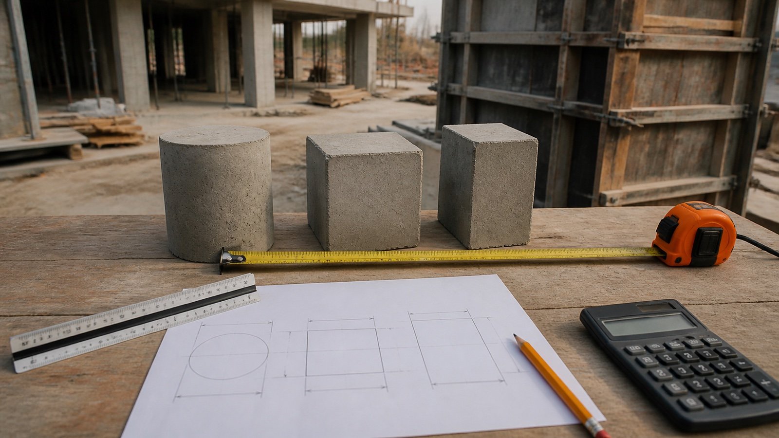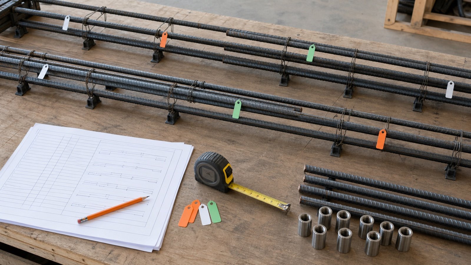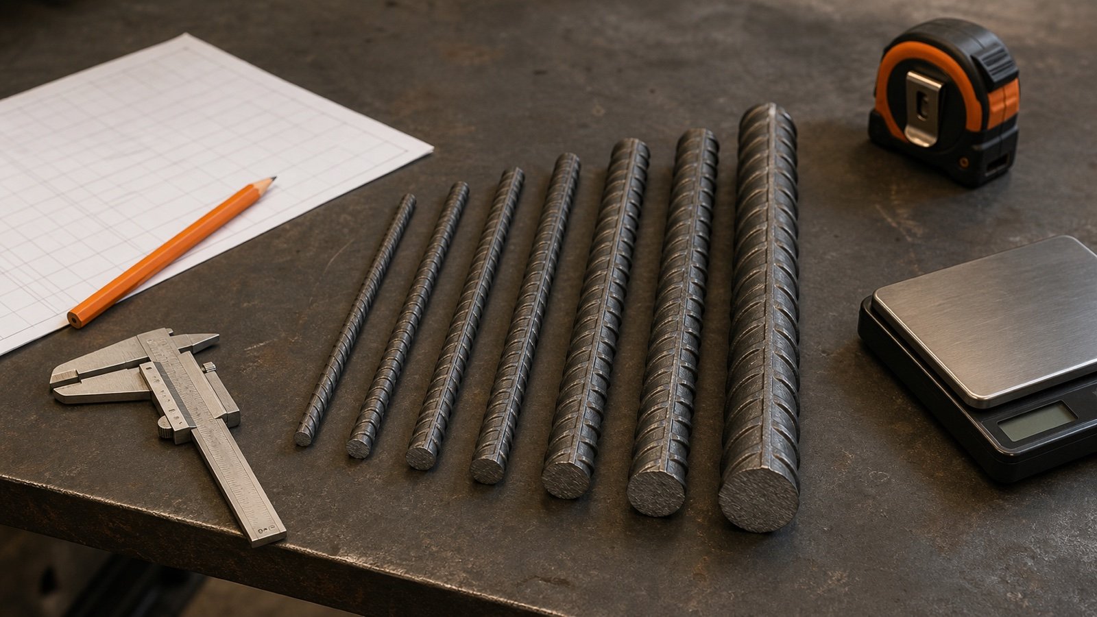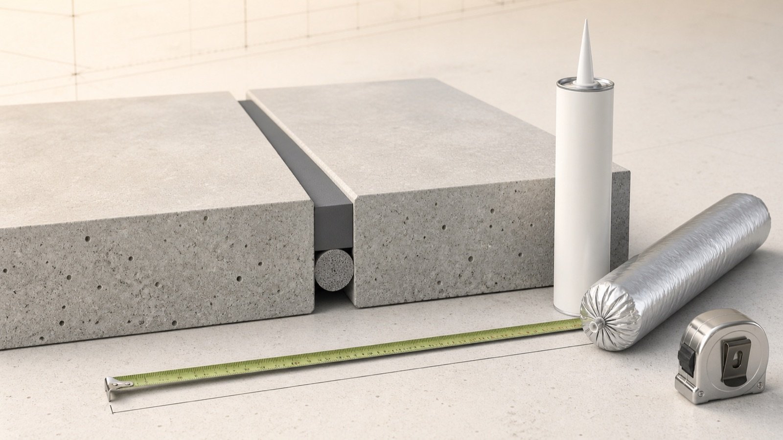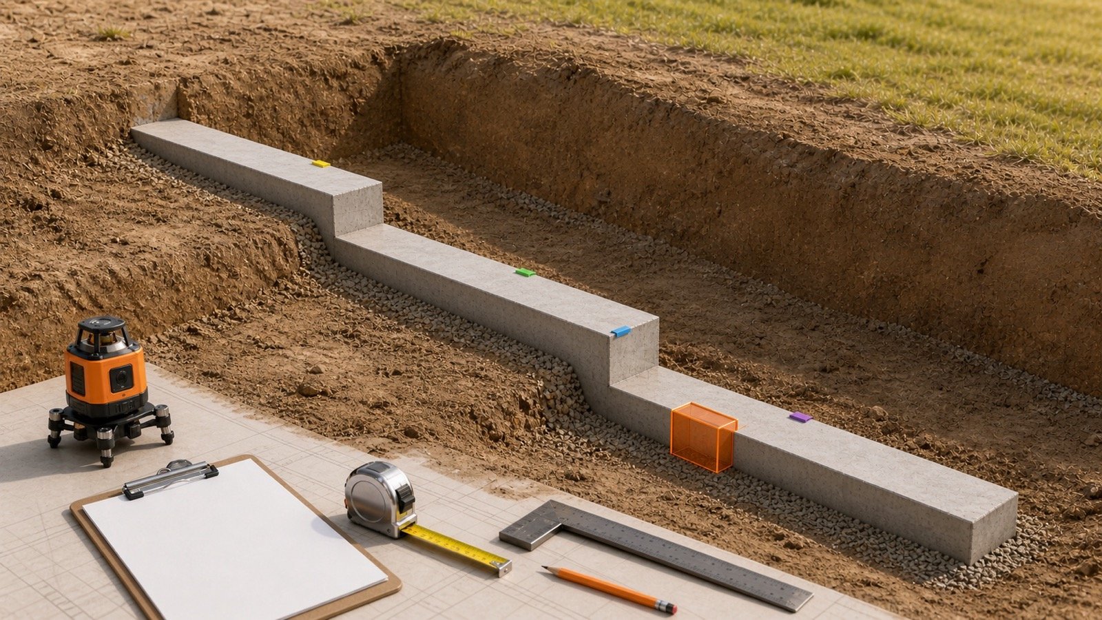
How do you calculate concrete beam formwork area?
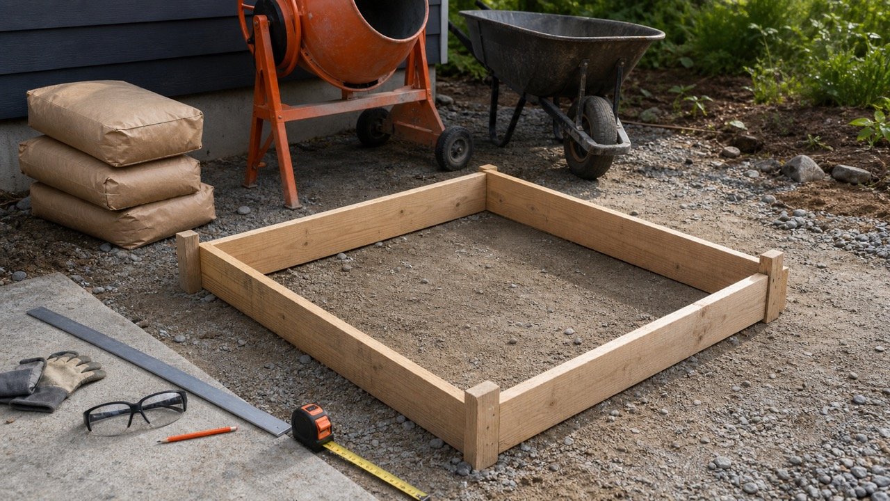
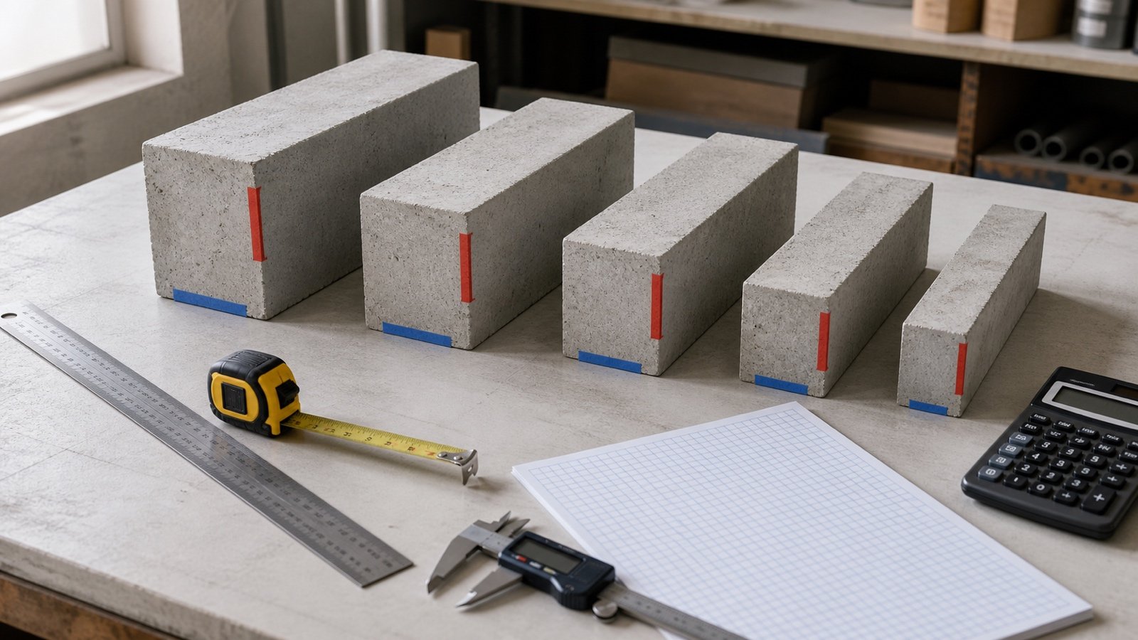
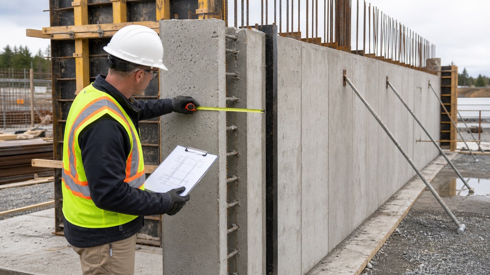
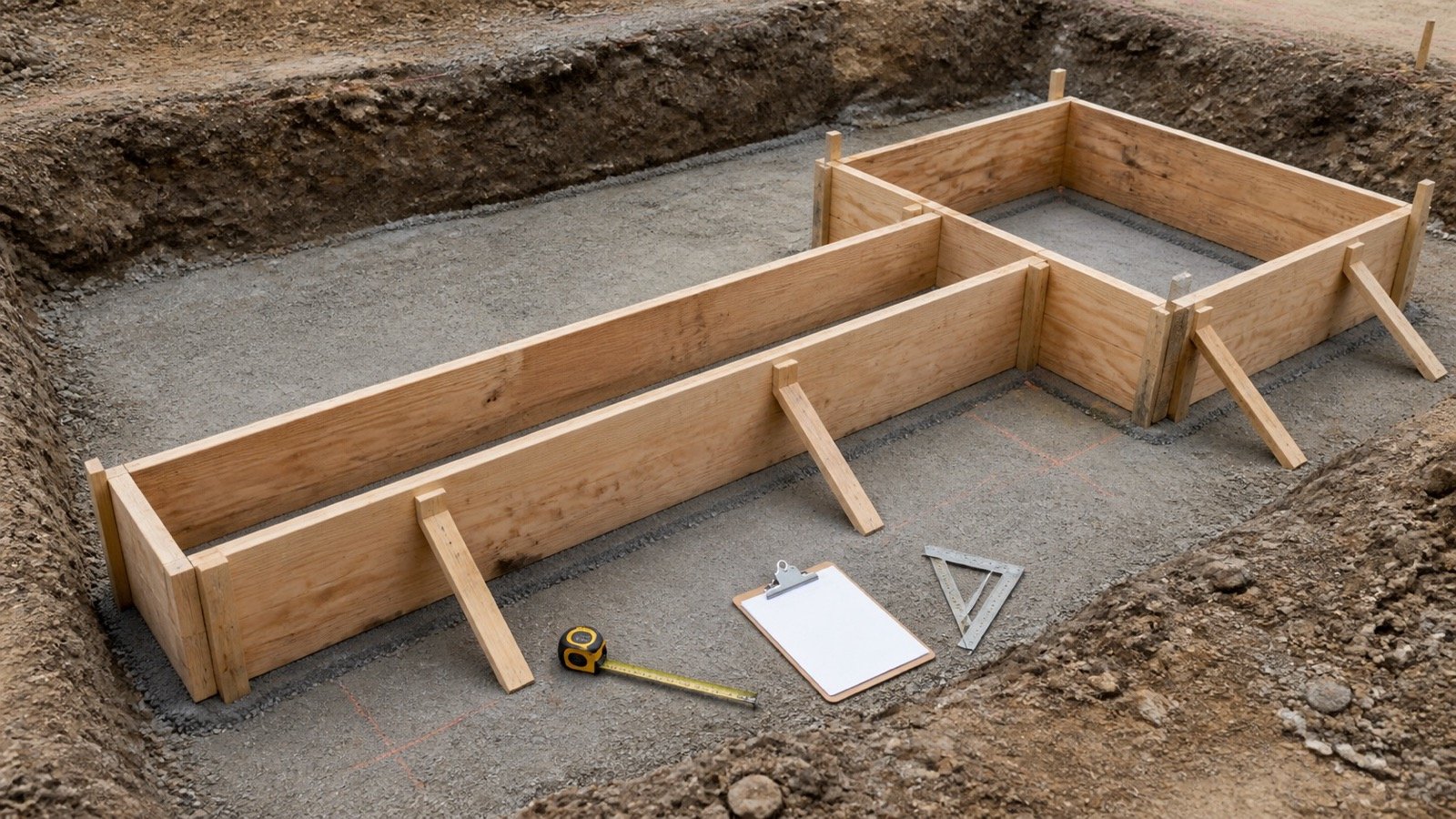
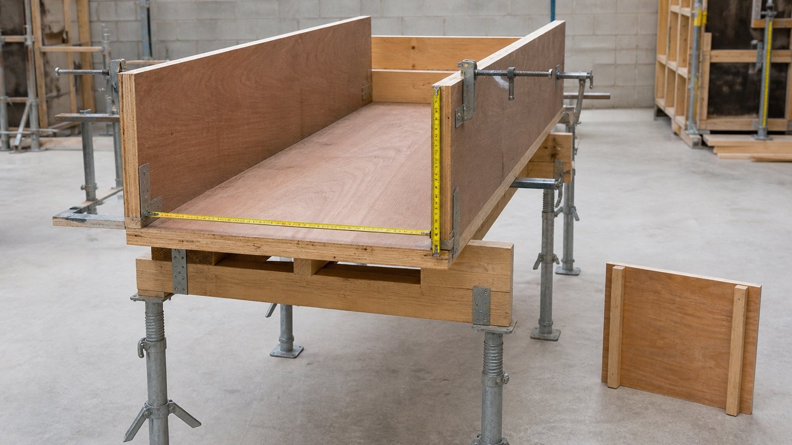
Multiply the net formed length by the width of each concrete-contact face. Add the soffit, left side, right side, and any separately formed end faces, then subtract only verified omissions.
Use the Concrete Beam Calculator to check the accepted beam length, width, and depth. Record the formwork result in square metres or square feet because concrete volume and form contact area use different units.
The common `(width + 2 × depth) × length` formula works when the soffit and 2 equal-depth sides need forms. It fails when the slab owns part of the side depth, the beam sits against ground, one side is attached, an end needs a bulkhead, or an intersection interrupts a face.
What does beam formwork area measure?
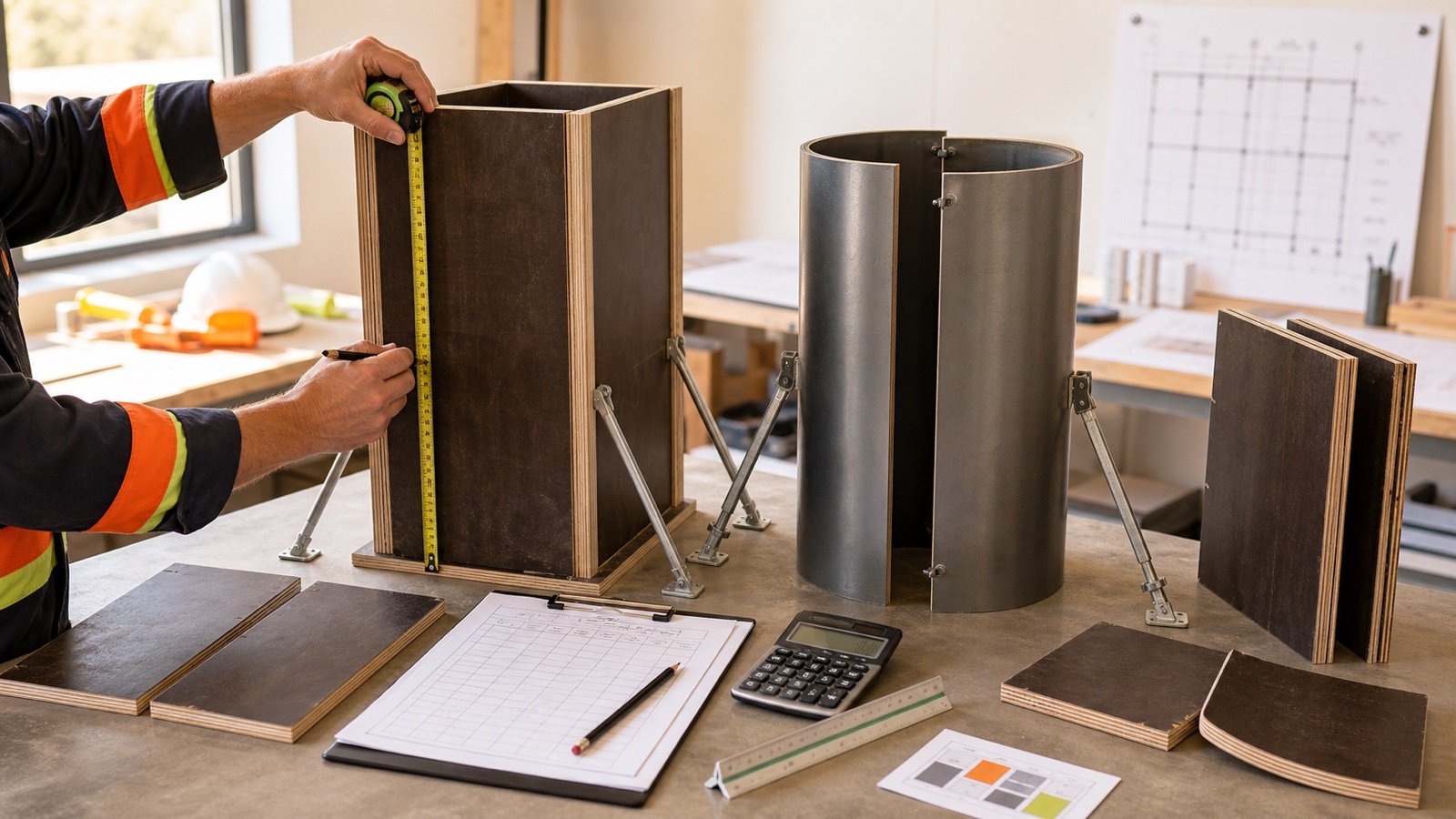
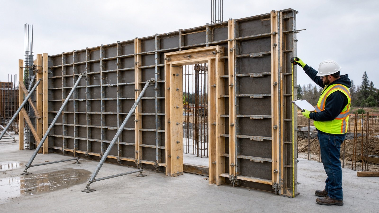
The result measures the net surface where form sheathing or a permanent form contacts fresh concrete. Estimators can use it for a measured-work schedule and as one input to a form-system layout.
Contact area alone cannot determine sheet count, panel modules, cut pieces, joints, ties, clamps, walers, bearers, shores, reshores, labour, release agent, lifting equipment, reuse cycles, or cost. The approved form design, selected product system, pour sequence, finish, access, stock condition, and supplier layout control those quantities.
| Record | Unit | Use |
|---|---|---|
| Beam concrete | m³, ft³, or yd³ | Measures the accepted concrete zone |
| Form-contact area | m² or ft² | Measures net formed faces |
| Form-system inventory | Panels and components by product code | Builds the forms and temporary support |
| Cycle record | Sets, locations, pours, and dates | Tracks approved reuse and simultaneous work |
Which records control the face schedule?
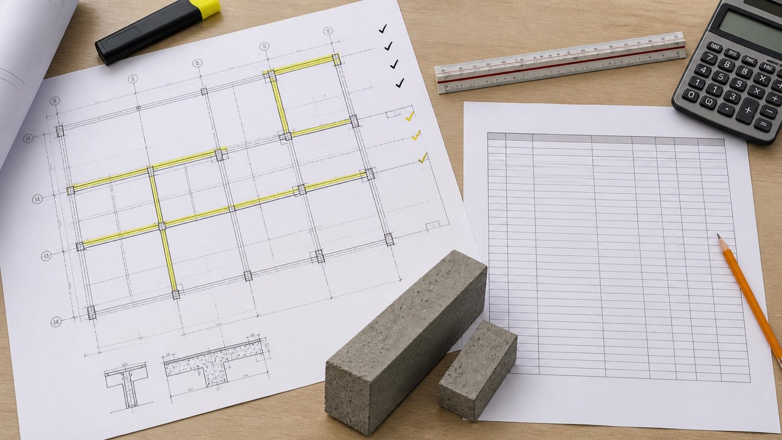
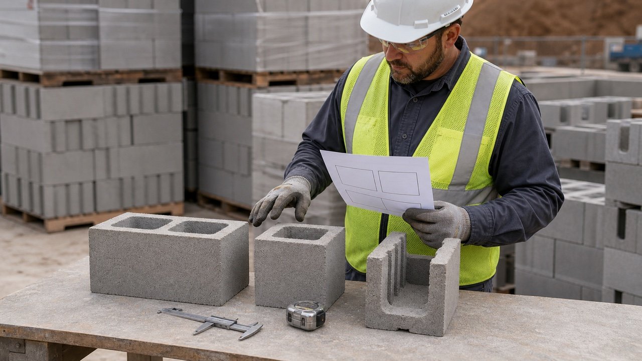
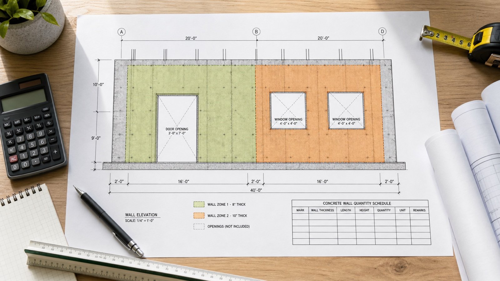
Use the current framing plan, beam schedule, sections, slab details, joint details, finish specification, measurement rules, formwork drawings, and pour sequence. Record the revision beside the affected group.
| Record | Quantity check |
|---|---|
| Framing plan | Beam mark, location, supports, count, level, and formed length |
| Beam schedule | Clear width, overall depth, beam type, and section changes |
| Slab sections | Slab thickness, downstand depth, upstand condition, and edge condition |
| Support and joint details | Column, wall, beam intersections, stop ends, and construction joints |
| Specifications or bill rules | Formwork classification, finish, permanent forms, exclusions, and measurement basis |
| Formwork drawings | Panels, joints, supports, loads, platforms, sequence, and revision |
RICS NRM 2 separates sides and soffits of isolated beams, sides and soffits of attached beams, and sides of upstand beams in its UK detailed-measurement framework. It also separates regular from irregular shapes and records propping-height bands. Those distinctions show why a beam label alone cannot set the face count.
Which face-by-face formula should you use?
Convert all linear dimensions to one unit. Calculate each formed face, then add the accepted areas.
Soffit area = net formed length × clear soffit width
Left-side area = net formed length × formed left-side depth
Right-side area = net formed length × formed right-side depth
Net beam formwork area = soffit + left side + right side + formed ends − verified omissions
For a regular beam with a formed soffit and 2 equal side depths, the formula becomes `(width + 2 × formed side depth) × length`. Keep end bulkheads and intersection adjustments outside that shortcut.
Worked example: isolated elevated beam
An isolated rectangular beam has a 6.00 m net formed length, 0.25 m soffit width, and 0.45 m formed depth on each side. Its supports occupy the beam ends, so this row has no separate end form.
| Face | Calculation | Area |
|---|---|---|
| Soffit | 6.00 × 0.25 | 1.500 m² |
| Left side | 6.00 × 0.45 | 2.700 m² |
| Right side | 6.00 × 0.45 | 2.700 m² |
| Total | 1.500 + 2.700 + 2.700 | 6.900 m² |
The shortcut gives the same result: `(0.25 + 2 × 0.45) × 6.00 = 6.900 m²`. The face rows still show which surfaces created the total.
A separately formed end with this 0.25 m × 0.45 m section would add 0.1125 m². Add the end only when the detail and selected measurement rules require a bulkhead at that location.
How does a slab-attached beam change the side depth?
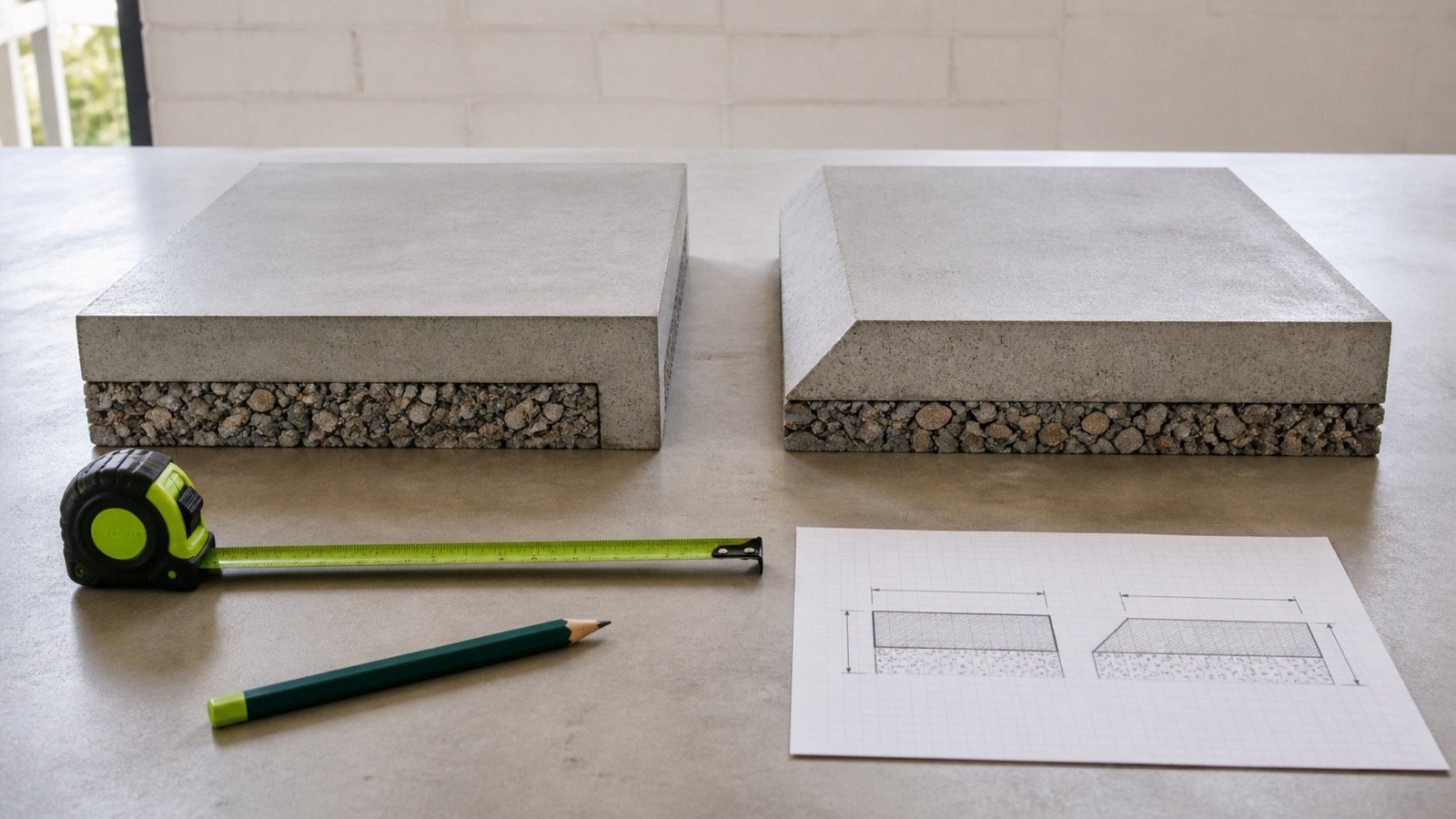
Measure the vertical side face that the beam form will create. A downstand beam cast with a slab often has side forms only below the slab soffit, while the slab form system owns the adjoining slab zone.
HKIS gives separate side-form treatment for an edge beam and for a beam where slab concrete is cast between beams. Its example uses the beam depth below the slab for the slab-attached side faces and instructs the user to adjust intersections as needed. The document covers a defined BIM measurement workflow rather than every contract.
Worked example: 3 attached downstand beams
Each beam has a 4.80 m formed length, 0.30 m soffit width, 0.60 m overall depth, and a 0.15 m slab thickness. The accepted formed side depth is 0.60 − 0.15 = 0.45 m.
| Face | Per beam | 3-beam group |
|---|---|---|
| Soffit | 4.80 × 0.30 = 1.440 m² | 4.320 m² |
| 2 downstand sides | 2 × 4.80 × 0.45 = 4.320 m² | 12.960 m² |
| Total | 5.760 m² | 17.280 m² |
Using the 0.60 m overall depth for both side forms would give `(0.30 + 2 × 0.60) × 4.80 = 7.200 m²` per beam. That overstates each beam by 1.440 m² and the group by 4.320 m² under this accepted slab-attached condition.
Do beam ends need formwork?
Add a beam end or stop-end face when the construction sequence leaves fresh concrete against a bulkhead. A beam ending at a column or wall may have no separate end form because the support or joint detail controls the closure.
| Condition | Takeoff action |
|---|---|
| Beam terminates at a formed construction joint | Add the accepted stop-end contact area |
| Beam meets a column or wall in one continuous pour | Follow the support and joint detail; avoid an invented end face |
| Precast or permanent end closure | Record the component under its product or permanent-form scope |
| Sloping, stepped, or irregular end | Calculate the actual formed shape from the approved detail |
List each end separately. Multiplying the section area by 2 assumes that both ends require identical forms, which may conflict with the pour sequence.
How do ground beams change the face count?
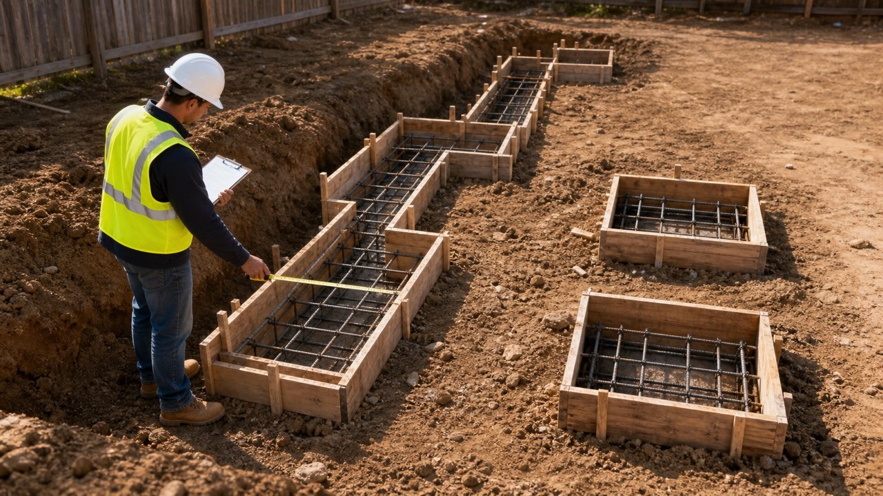
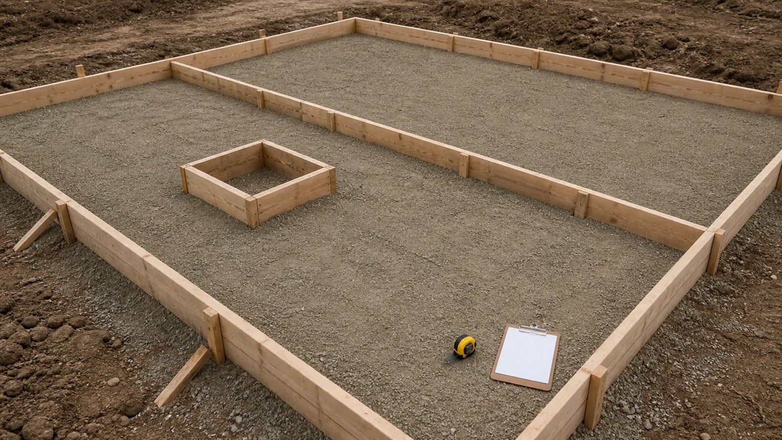
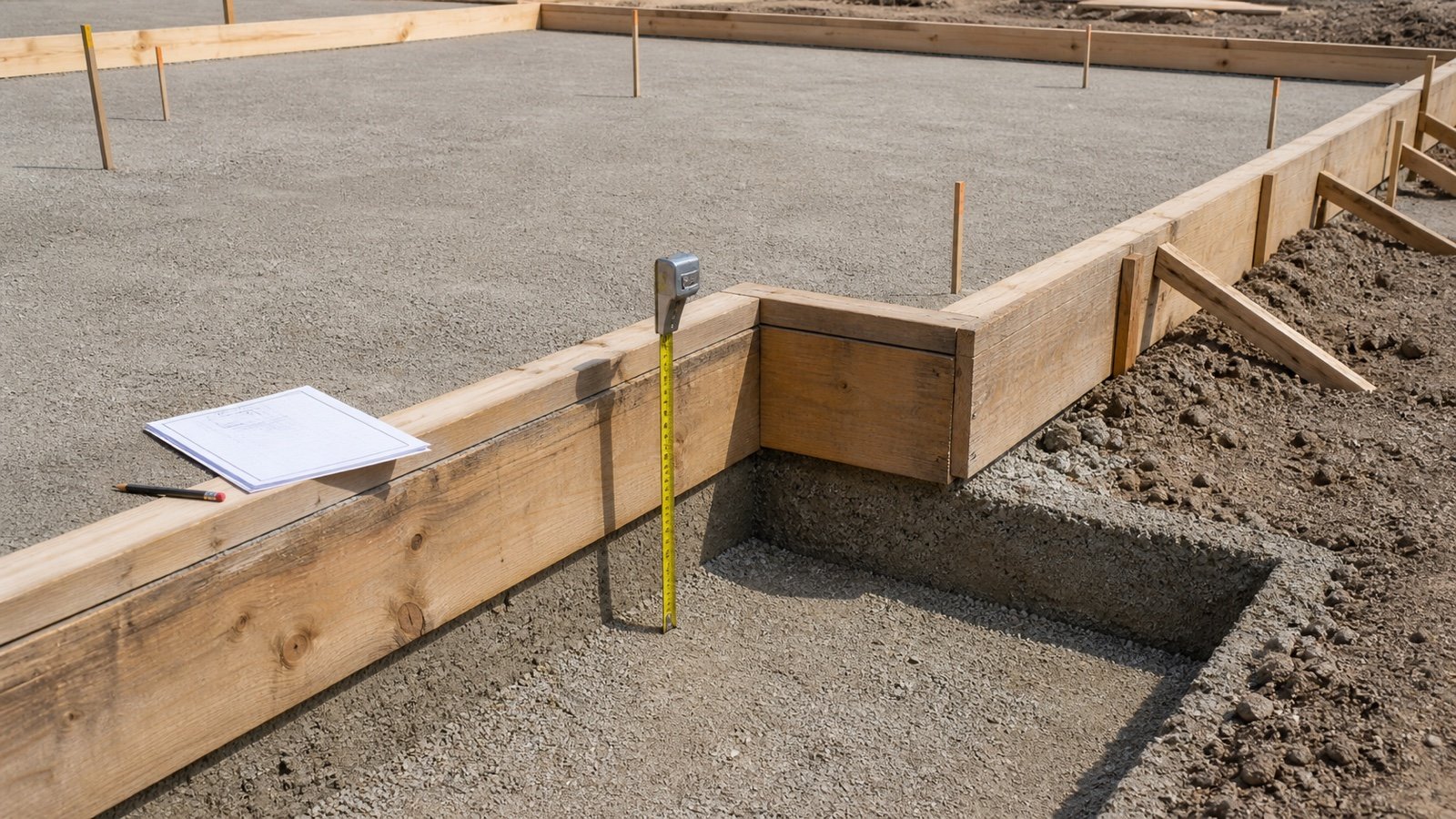
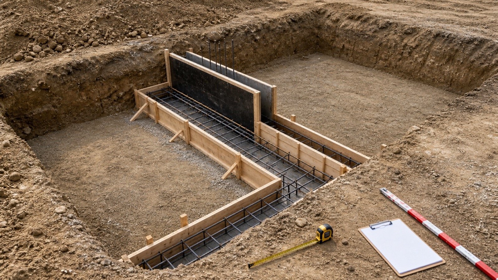
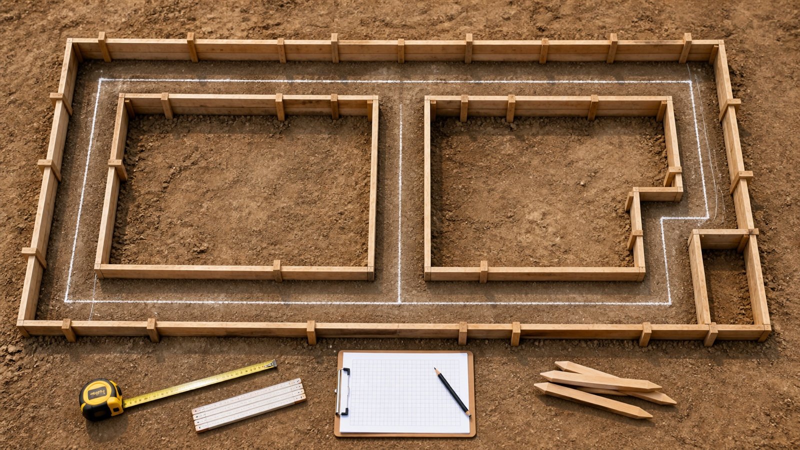
Record the surfaces that need constructed forms. A ground beam may have side forms, trench faces, blinding below, a permanent form, or a full supported soffit depending on the approved method and ground condition.
- A soffit cast on approved blinding has no separate soffit form-contact panel in that method.
- A side cast against accepted earth or permanent form follows that boundary and its measurement rule.
- An excavated trench does not prove that earth contact is permitted or dimensionally suitable.
- An edge beam can expose one side deeper than the other.
Keep excavation support, blinding, waterproofing, protection, permanent forms, and temporary works on their own schedule rows. The beam section formula cannot decide the construction method.
How should intersections and openings be measured?
Mark each face interruption on the formwork drawing and apply the project measurement rule. Use net geometry for a planning worksheet, while a contract bill may prescribe its own deduction threshold or included work.
HKIS instructs users to omit formwork at beam intersections with slabs or structural walls as appropriate, except beam ends, in its substructure-beam workflow. RICS NRM 2 has defined classifications and rules for formwork within its UK framework. Record which rule controls the issued quantity.
| Interruption | Record |
|---|---|
| Column or wall support | Face, width, depth, pour sequence, and matching support boundary |
| Secondary beam | Intersection face and selected measurement treatment |
| Slab zone | Slab thickness, soffit level, and downstand or upstand ownership |
| Blockout, recess, or opening | Dimensions, return faces, closure pieces, and governing deduction rule |
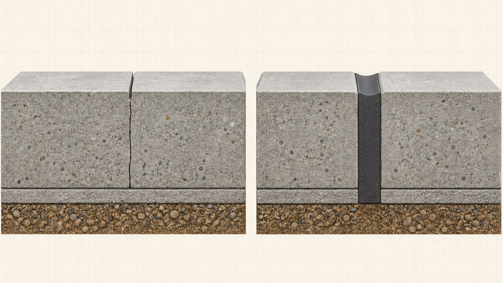
| Construction joint | Joint location, stop-end geometry, and issue reference |
Keep the gross face area, each accepted addition or omission, and the net total visible. A checker can then reproduce the quantity without guessing how an intersection was treated.
How do imperial dimensions convert to square feet?
Convert inches to feet before multiplying, or convert the final square-inch area with an area factor. NIST Handbook 44 Appendix C records 12 inches as 1 foot and 1 square foot as 144 square inches.
A 20 ft beam has a 12 in soffit and two 18 in formed sides. Convert 12 in to 1 ft and 18 in to 1.5 ft.
(1 ft + 2 × 1.5 ft) × 20 ft = 80 ft²
Dividing a square-inch result by 12 produces the wrong unit conversion. Divide by 144, or convert the linear dimensions before calculating area.
Can contact area be divided by plywood-sheet area?
The quotient compares 2 areas. A purchase count needs a cut and joint layout that respects face dimensions, sheet direction, structural support, seams, overlaps, edge distances, finish, damage, and reuse.
A beam with 17.280 m² of group contact area can use fewer square metres of physical panels when the approved cycle reuses a form set. It can also need more sheathing than the net contact area because stock dimensions, offcuts, joints, closures, damage reserves, and simultaneous pours add material.
Record gross measured work, simultaneous form-set area, component inventory, and planned cycles separately. Use current supplier drawings and product instructions for proprietary systems.
Which beam shapes need developed-face geometry?
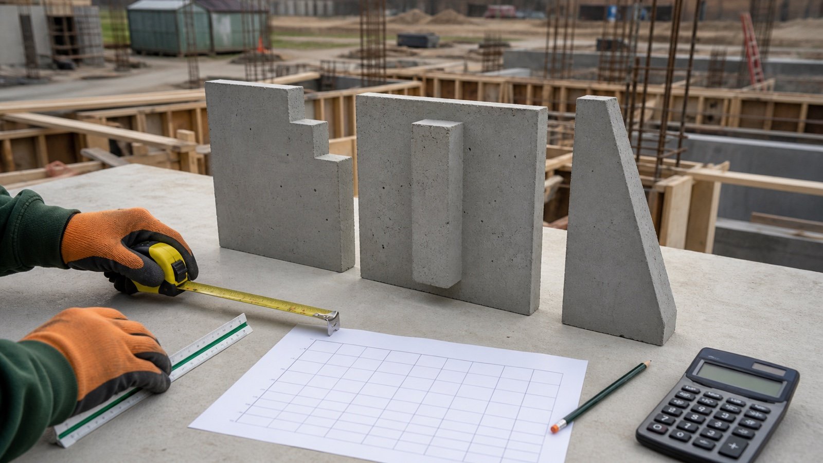
Tapered, haunched, stepped, curved, cranked, sloping, T-shaped, L-shaped, and profiled beams need a face schedule that follows the approved geometry.
- Split a stepped side into non-overlapping rectangles.
- Calculate a linearly tapered side as the approved trapezoid.
- Use the actual slant length for a sloping face.
- Use developed arc length for a curved face and state the radius.
- Separate rebates, chamfers, nibs, voids, liners, and permanent forms under the selected rules.
RICS NRM 2 treats square and rectangular beam shapes as regular in its formwork section and asks for a dimensioned description or diagram for irregular work. Another measurement standard may classify the same geometry differently.
Why must shores and stripping stay outside the area formula?
Square metres and square feet contain no information about wet-concrete load, construction loads, placement rate, panel capacity, shore spacing, bracing, foundations, wind, vibration, concrete strength, or loads from later work.
The Concrete Society describes side and soffit formwork for in-situ beams and notes that the soffit needs temporary support until the beam can carry its weight and additional imposed loads. For covered United States work, OSHA 29 CFR 1926.703 requires forms to support anticipated vertical and lateral loads, requires plans and revisions at the jobsite, and sets inspection and strength-based removal conditions.
The qualified temporary-works design, project drawings, concrete test evidence, selected system instructions, and governing law control erection, inspection, reshoring, stripping, and reuse.
Which mistakes change a beam formwork quantity?
- Using concrete volume as formwork area.
- Applying 3 faces to ground-supported, attached, edge, or upstand beams without checking the detail.
- Using overall depth where only the downstand below a slab is formed.
- Adding both end faces when supports close the beam.
- Ignoring column, wall, slab, secondary-beam, and joint intersections.
- Using outside panel dimensions instead of concrete-contact dimensions.
- Mixing millimetres with metres or inches with feet.
- Combining unequal side depths in one shortcut.
- Converting contact area directly to sheets or panels.
- Treating total project area as simultaneous form-set inventory.
- Applying a universal allowance, reuse count, labour rate, or stripping time.
- Deriving ties, walers, shores, bracing, or pour rate from area.
Final formwork-area check
- Freeze the current plan, schedule, sections, formwork drawings, and revisions.
- Use the Concrete Beam Quantity Takeoff to reconcile beam marks, counts, lengths, sections, and boundaries.
- List soffit, left side, right side, and each formed end separately.
- Record attached, ground-supported, edge, upstand, permanent-form, and irregular conditions.
- Show intersection additions and omissions beside the gross face areas.
- Retain full-precision calculations and the selected measurement rule.
- Keep panel inventory, temporary support, reuse cycles, labour, and cost in separate records.
- Record preparer, checker, unresolved conditions, and issue date.
Use the Concrete Slab Calculator and Concrete Column Calculator to check adjoining geometry. Return to the concrete planning hub for the full cluster. The calculation methodology explains units and rounding, and the corrections route accepts a source or arithmetic issue.
Sources and source scope
- HKIS BIM Measurement Information Requirements supports the scoped beam-depth-below-slab, side-form, and intersection treatment.
- RICS NRM 2 supports the stated UK detailed-measurement classifications.
- The Concrete Society's In-situ Beams guidance supports the side, soffit, sequence, and temporary-support context.
- NIST Handbook 44 (2026), Appendix C supports the unit relationships.
- OSHA 29 CFR 1926.703 supports the stated United States workplace boundaries.
Source scope: HKIS and RICS provide scoped quantity and measurement rules. The Concrete Society supports beam construction context. NIST supports unit relationships. OSHA supports the cited United States workplace requirements. These sources do not select a formwork system, panel layout, temporary support, pour sequence, reuse count, labour rate, cost, or structural design for a project.
Review note: Saleem Sial owns the research and editorial record. Formula fixtures, source checks, build validation, and rendered QA form the internal publication gate. Waseem Sial, External Reviewer and Engineer, is listed for ongoing external review; no completed review date is claimed.