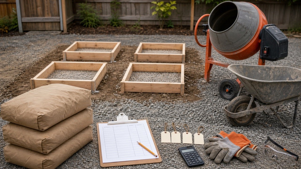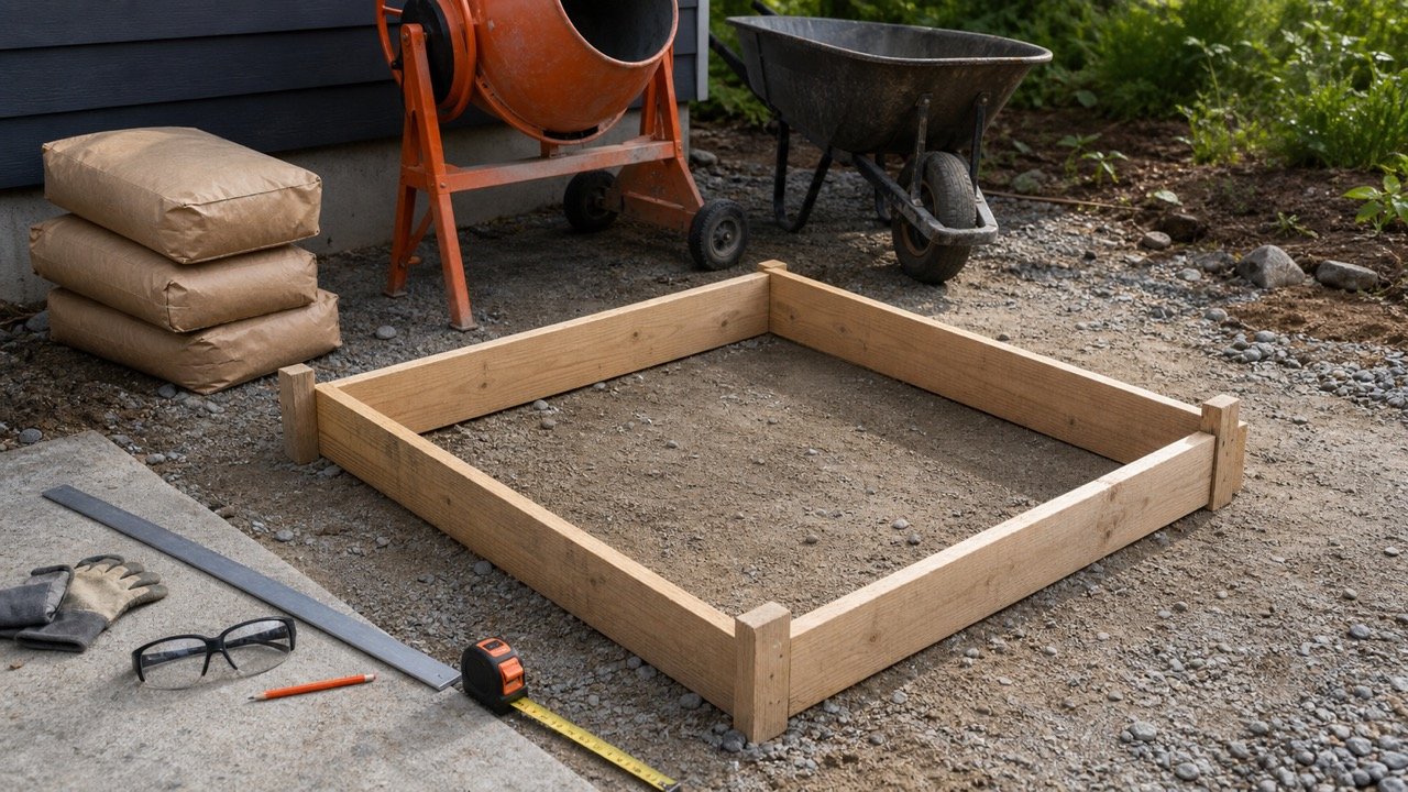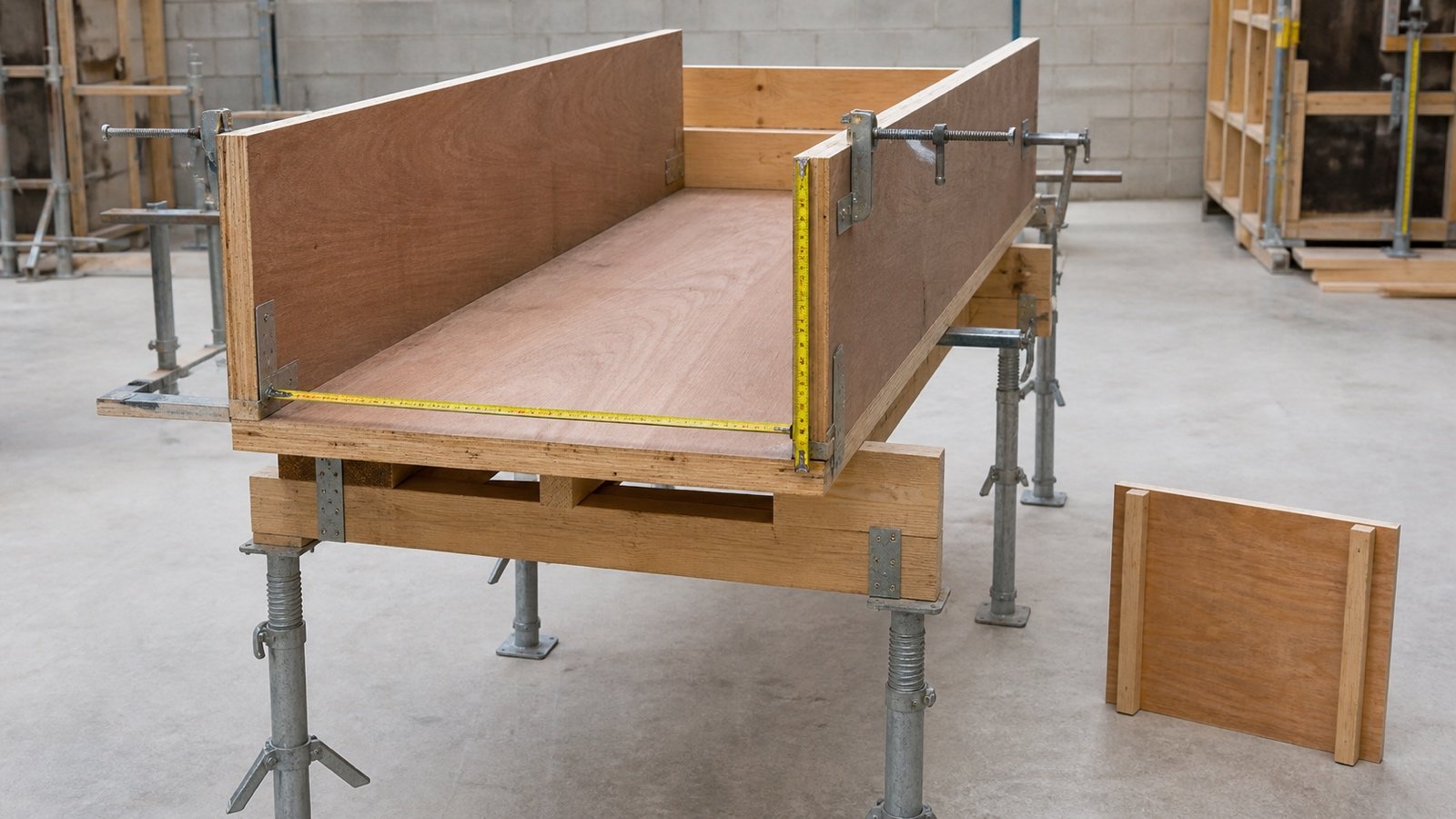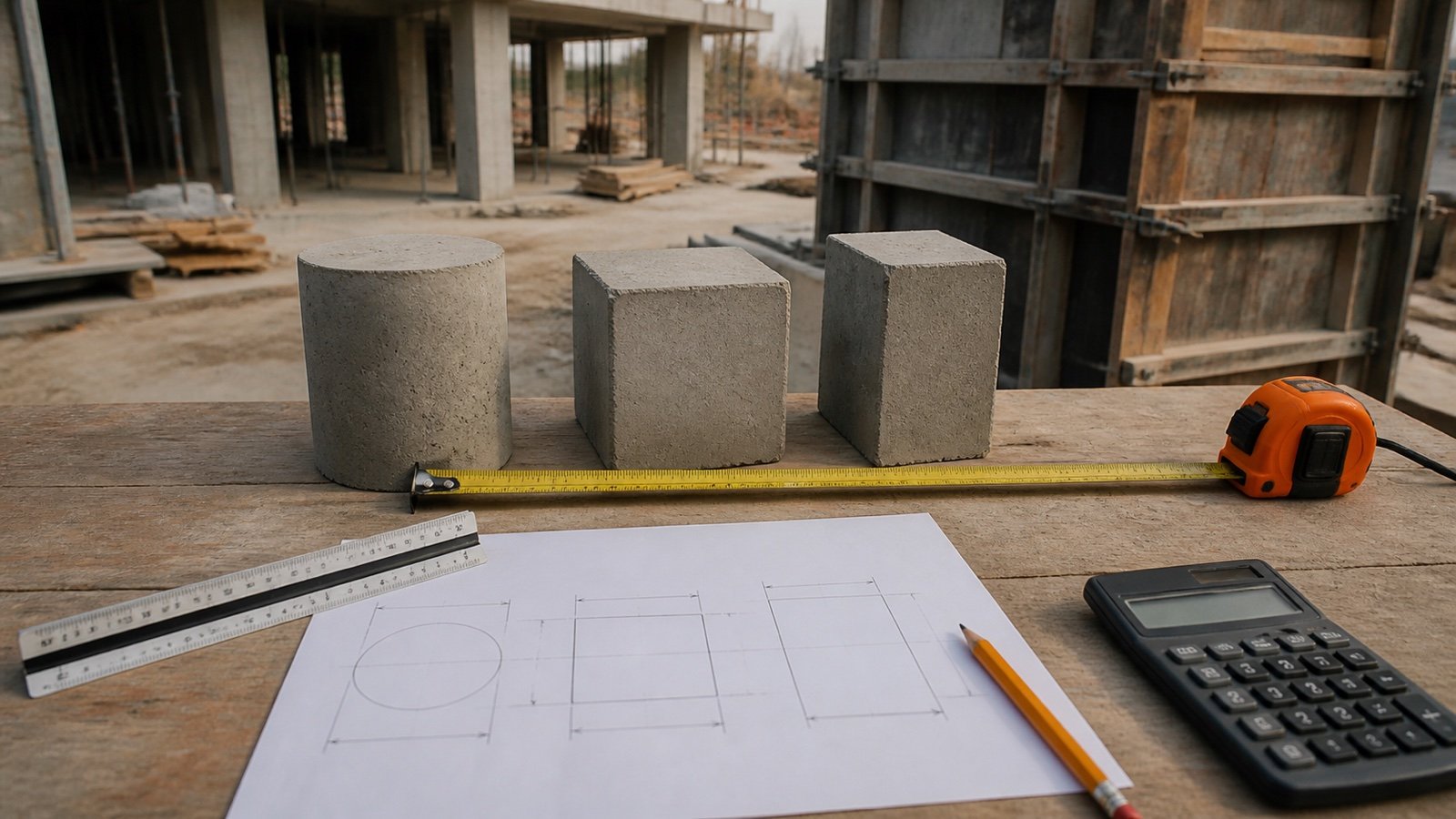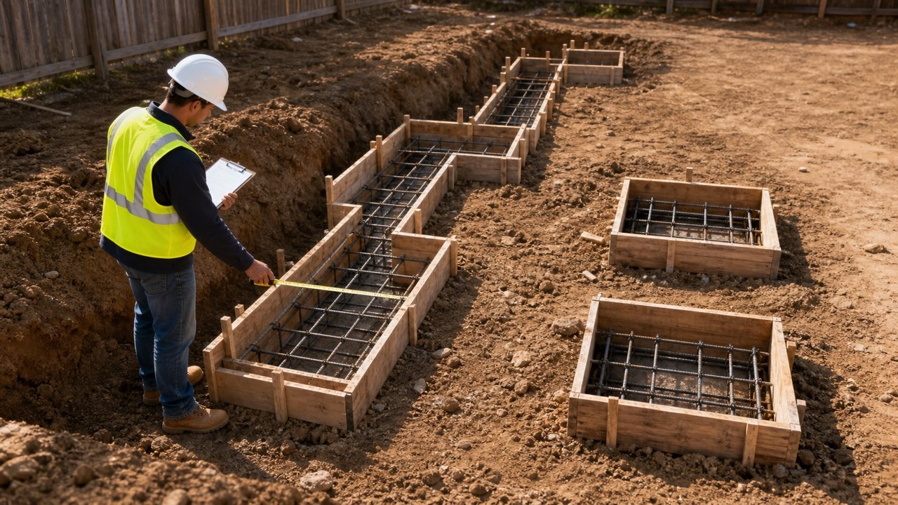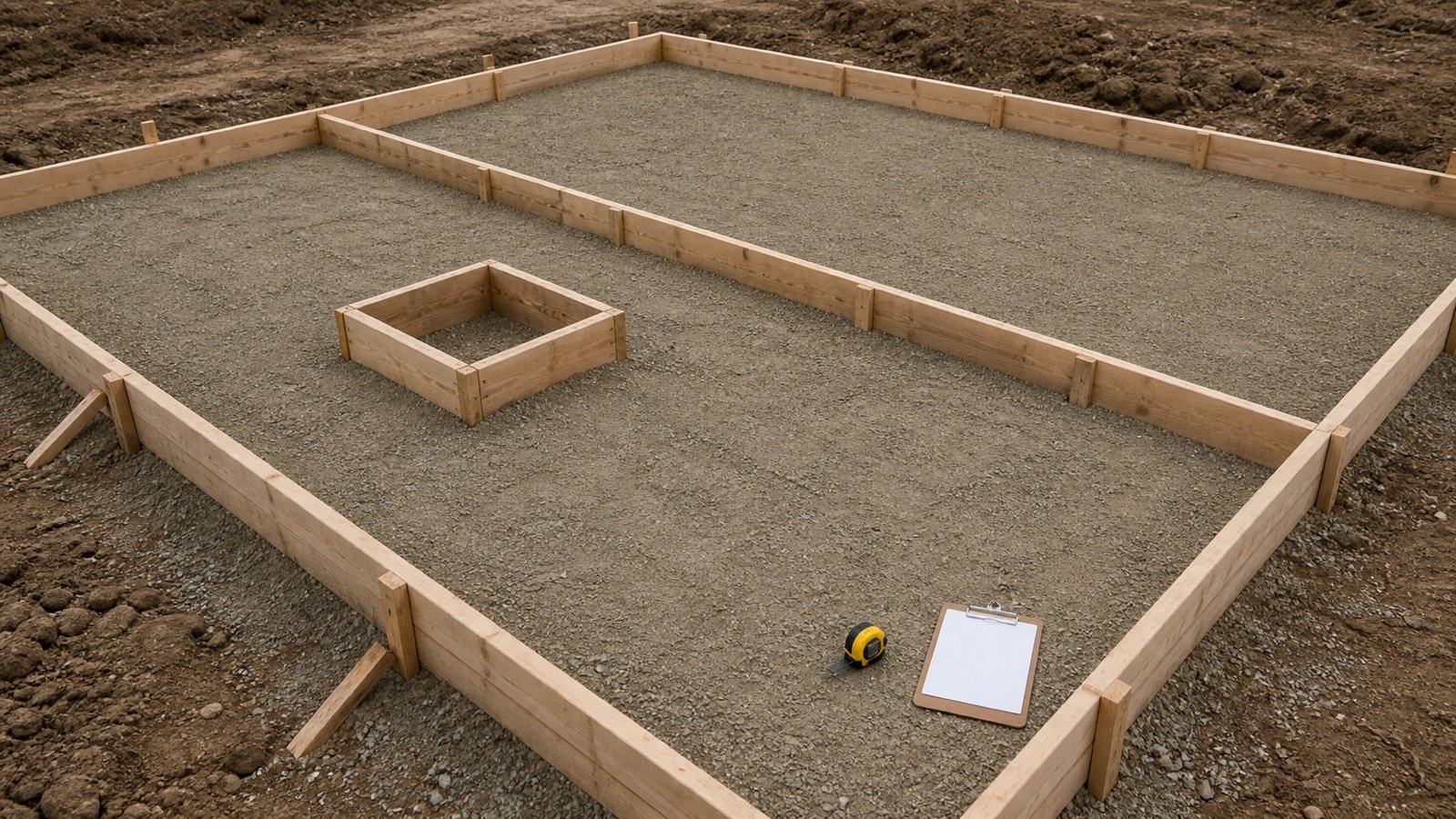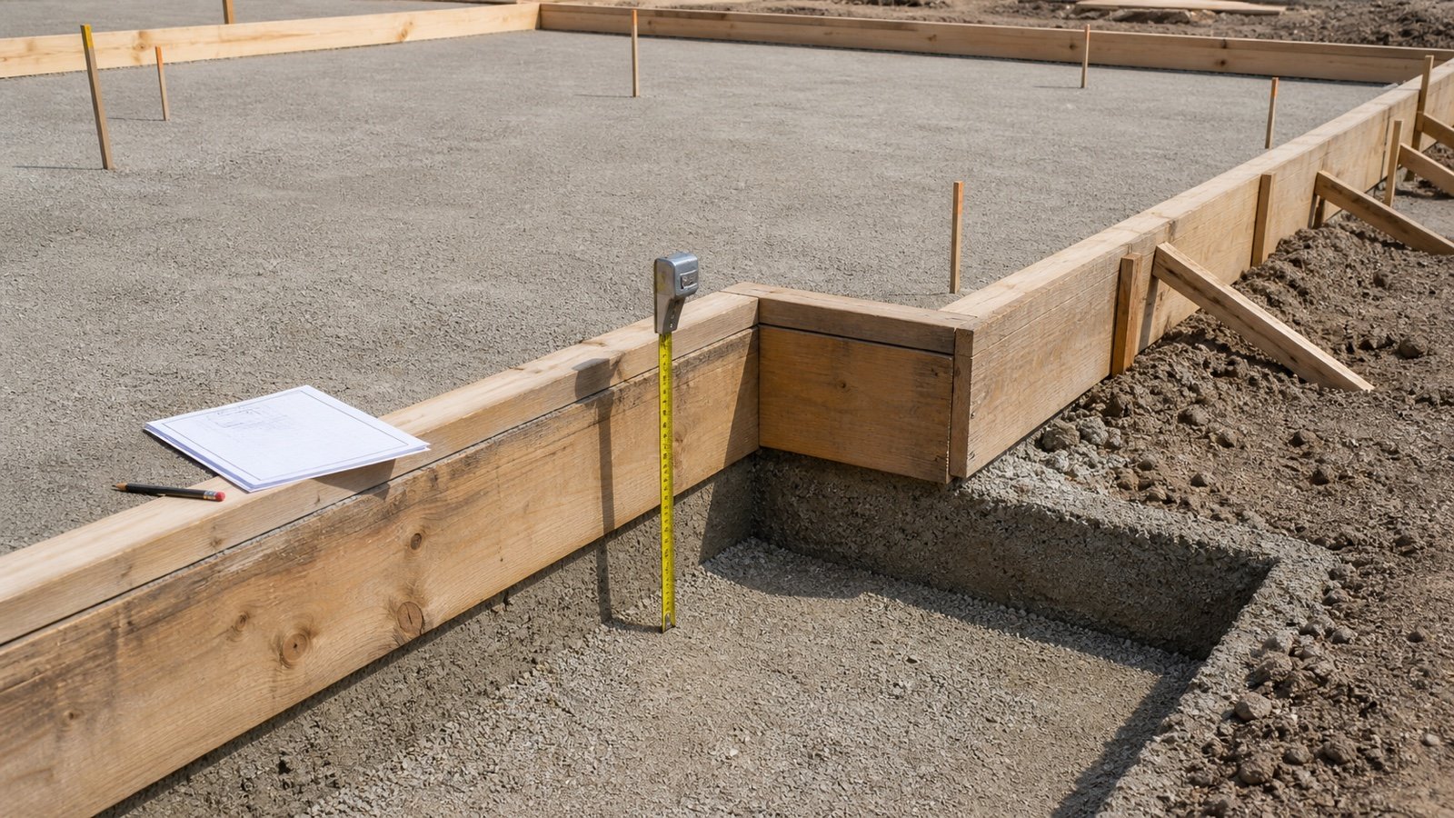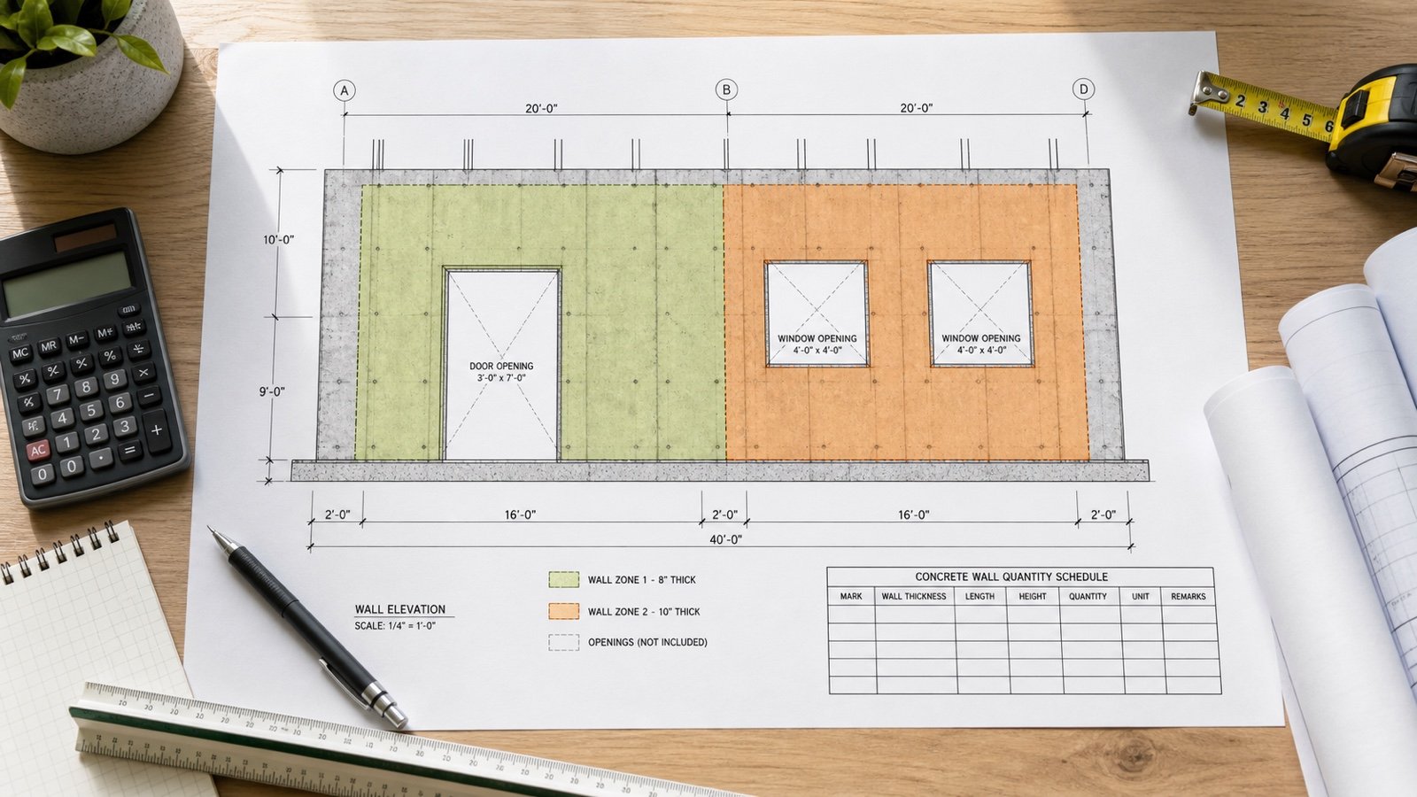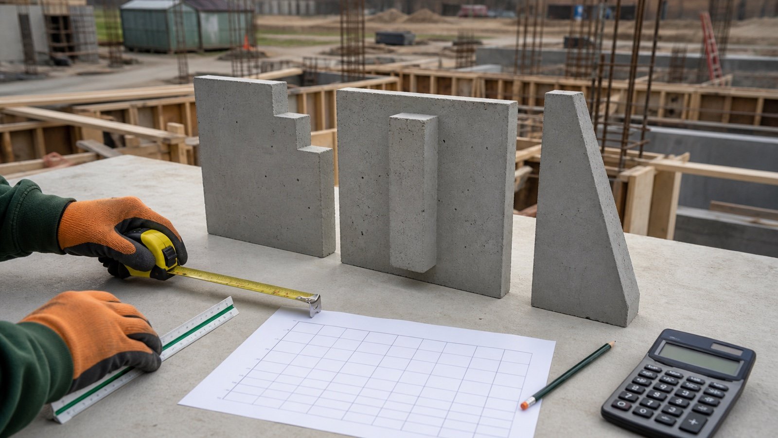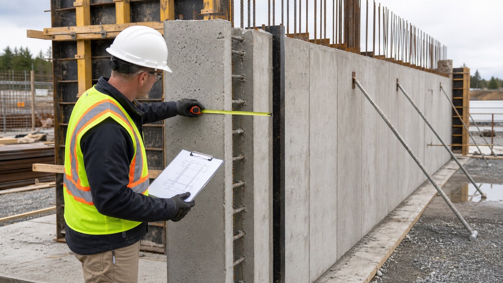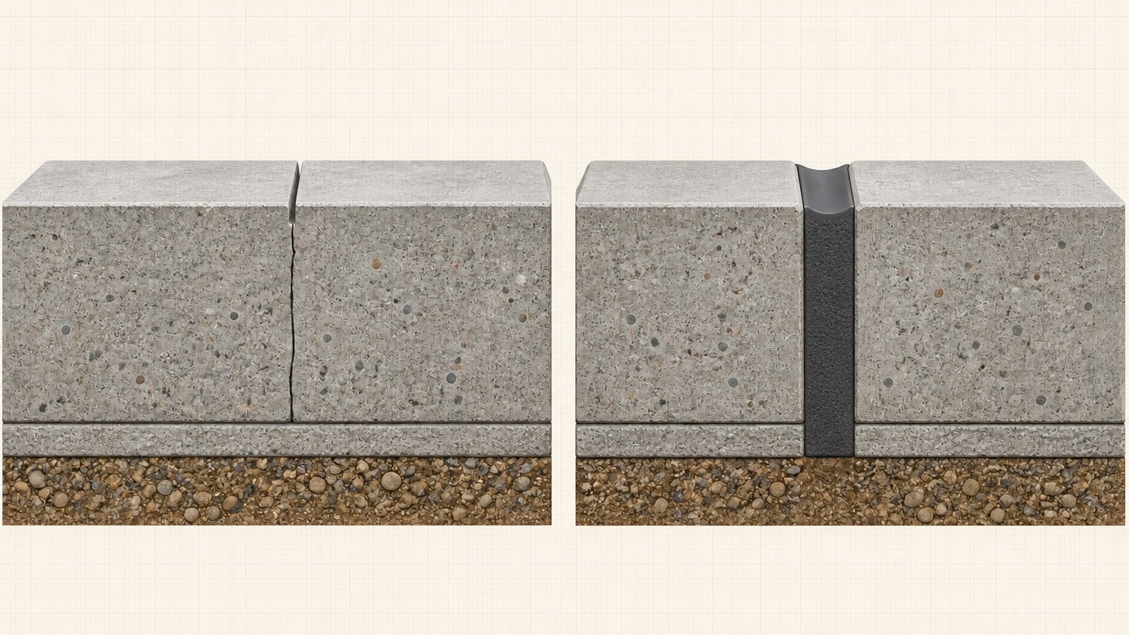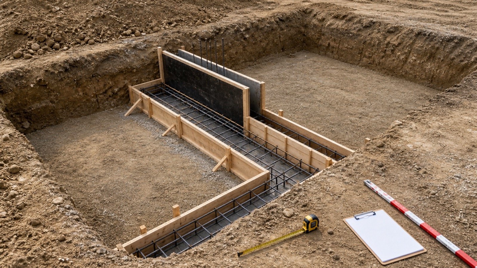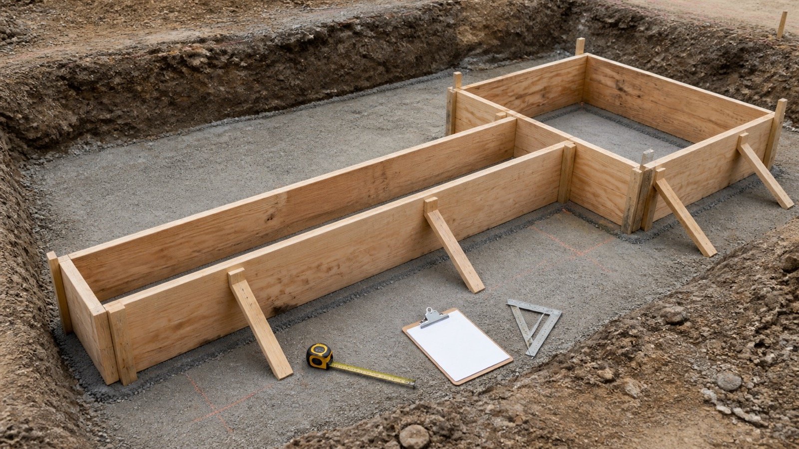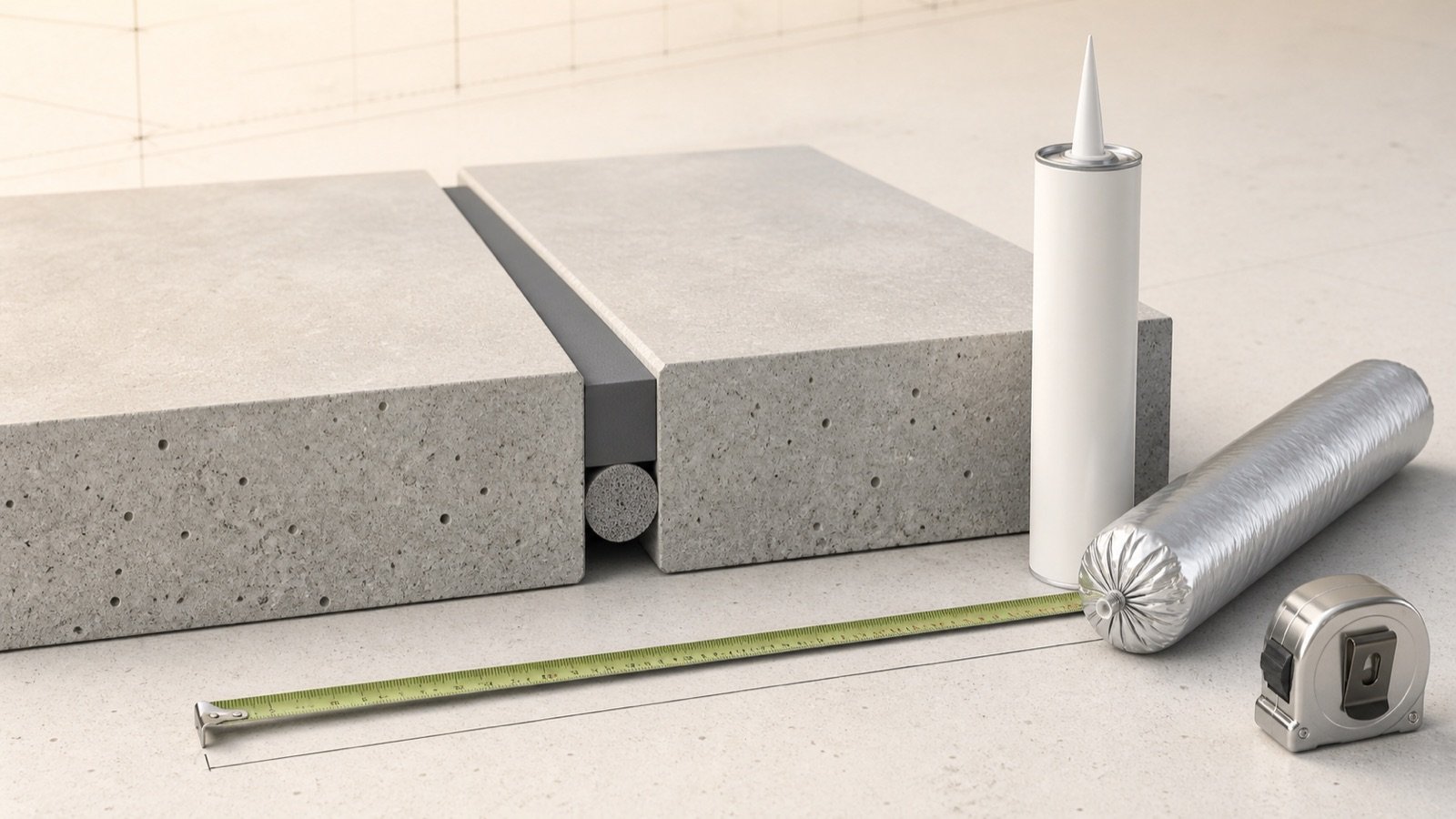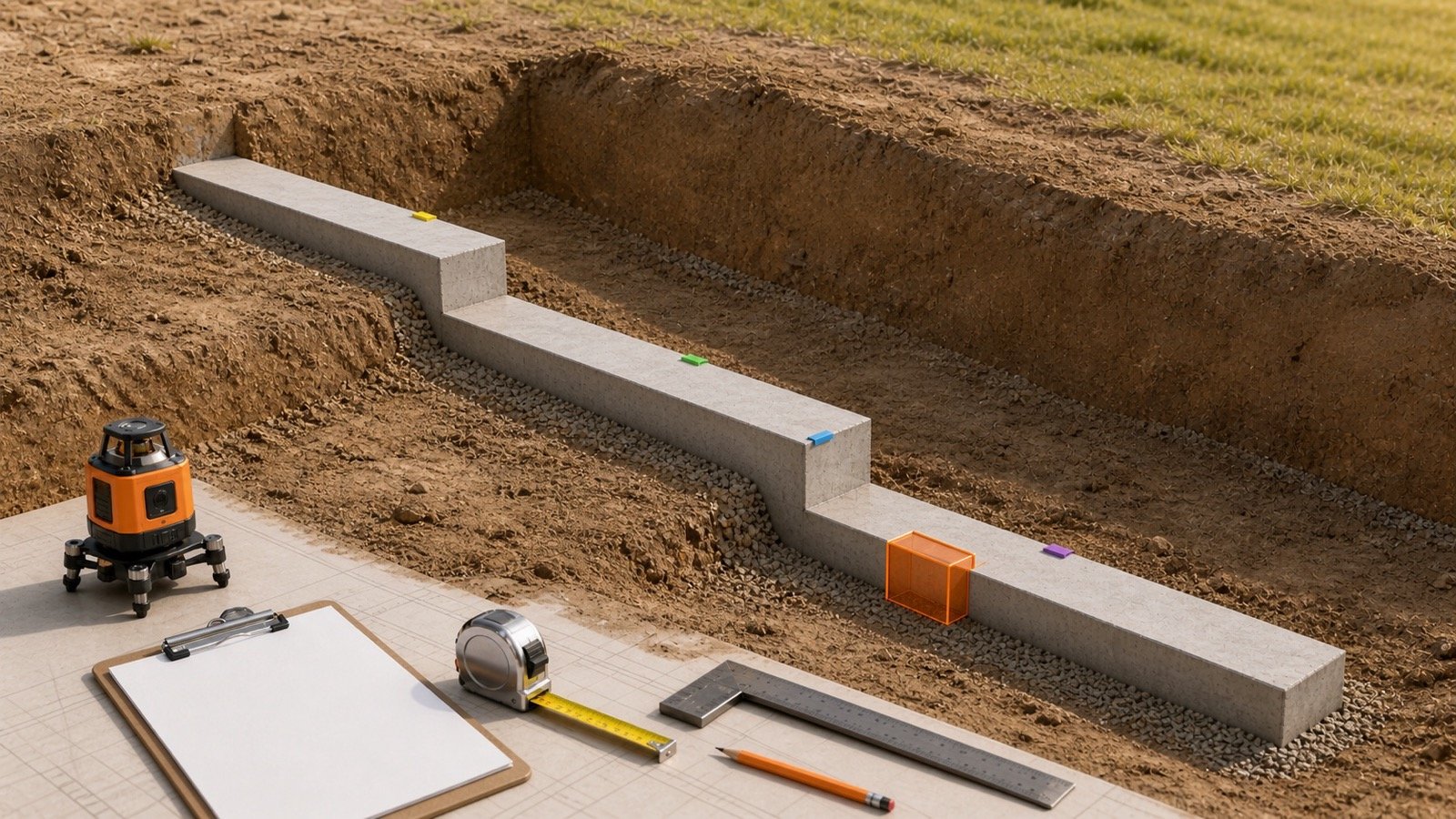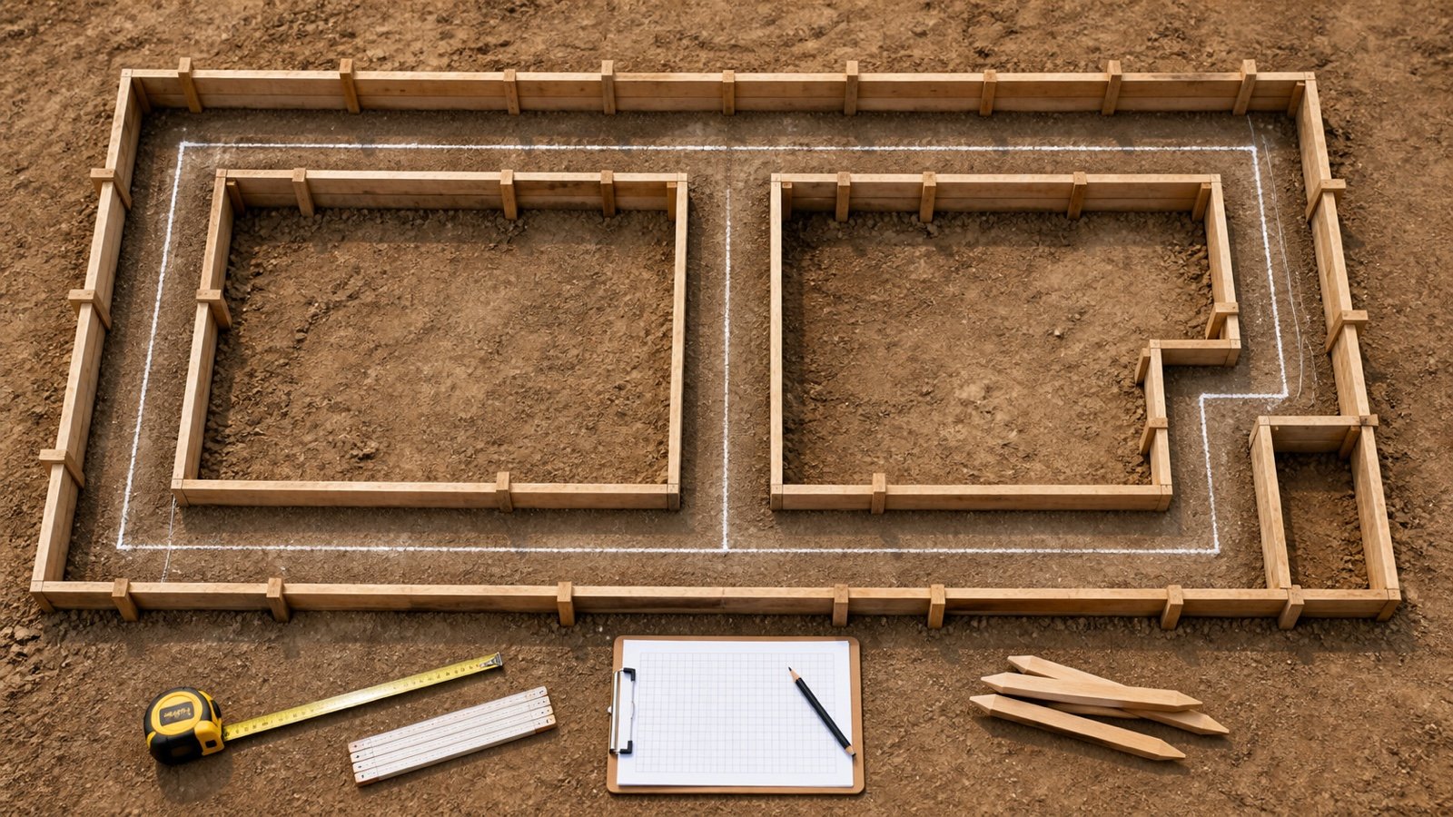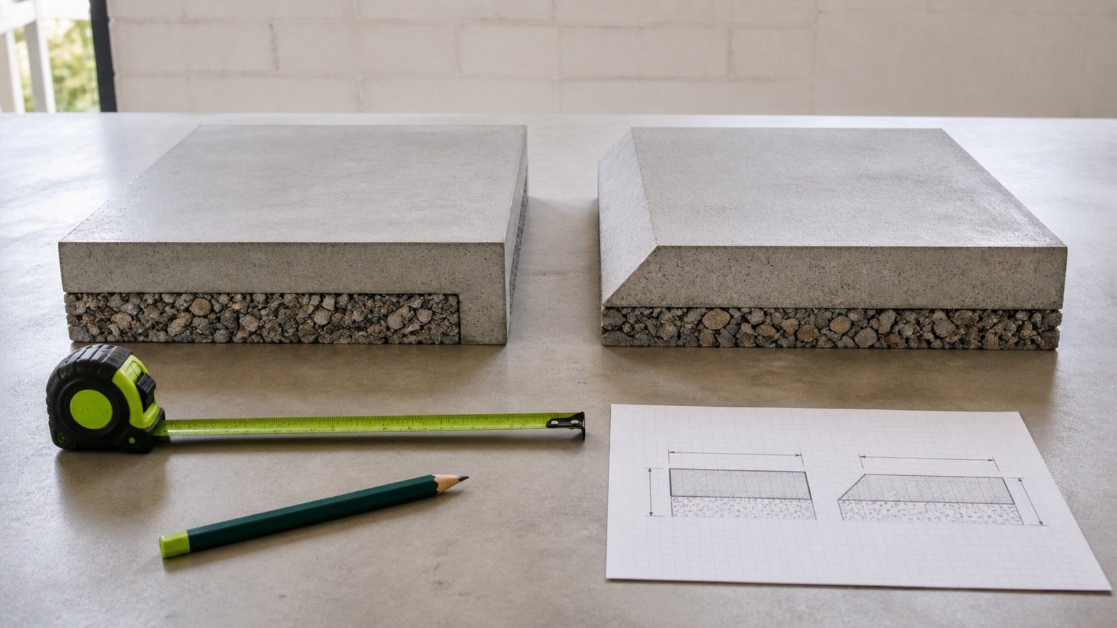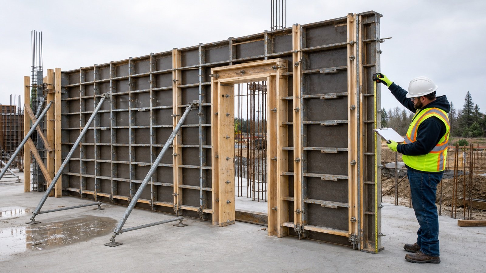
How do you calculate concrete wall formwork area?
Multiply wall length by formed height and by the number of formed main faces. Subtract opening face areas from every affected face, then add the opening returns, wall ends, stop ends, soffits, or steps that the project measures separately.
Main-face area = wall length × formed height × formed-face count
Use the Concrete Wall Calculator to check wall volume and opening volume. Record formwork in square metres or square feet because it measures contact surface, while concrete uses cubic units.
The common factor of 2 applies only when both broad faces require formwork. One-sided work, permanent forms, existing concrete, earth faces, and special systems need the approved construction detail and measurement rule.
Which quantities need separate records?
Keep four related quantities apart. Their units and decisions differ.
| Record | Unit | What it controls |
|---|---|---|
| Wall concrete | m³, ft³, or yd³ | Net concrete volume by wall mark and pour zone |
| Form-contact area | m² or ft² | Measured faces, returns, and ends in the selected rules |
| Form-set inventory | Panels and components by code | The approved assemblies needed at the same time |
| Cycle plan | Sets, pours, locations, and dates | Movement, inspection, repair, and reuse of each set |
Wall thickness changes concrete volume and the width of returns or stop ends. It leaves the broad face area unchanged when length and formed height stay the same.
What information controls the takeoff?
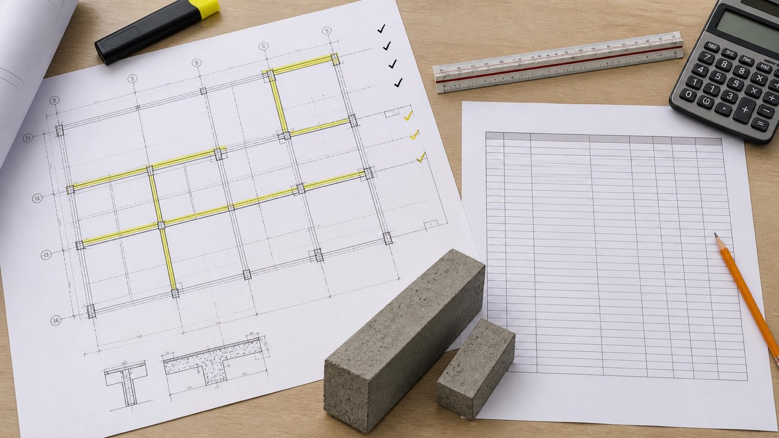
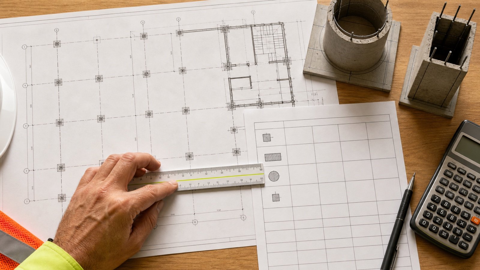
Use current structural drawings, wall schedules, sections, opening details, joint drawings, finish specifications, pour plans, measurement rules, and the approved form-system design. Record each source revision.
- Wall mark, level, grid, pour zone, and drawing revision.
- Length basis, including face, centreline, or segmented geometry.
- Base and top elevations for the formed height.
- Wall thickness and every thickness change.
- Number and identity of formed main faces.
- Opening width, height, depth, count, host zone, and return faces.
- Free wall ends, stop ends, construction joints, steps, sloping tops, and soffits.
- Intersections with footings, slabs, beams, columns, pilasters, and adjacent walls.
- Plain or special finish, battered or curved work, liners, and permanent forms.
- Selected contract measurement rule and its deduction thresholds.
HKIS includes wall mark, type, thickness, length, top and base levels, concrete designation, volume, and formwork area in its quantity-information requirements. Those fields help reconcile model output with the drawing record; they do not approve a construction method.
Which formulas apply to straight wall faces?
Convert all linear inputs to one unit before multiplying. Calculate each face or zone separately when its length, height, finish, slope, or form condition changes.
| Surface | Formula |
|---|---|
| One broad wall face | Length × formed height |
| Two broad wall faces | Length × formed height × 2 |
| Rectangular opening on one face | Opening width × opening height |
| Opening face deduction on matching faces | Opening width × opening height × affected-face count |
| One rectangular opening return | Return edge length × wall thickness |
| One vertical wall end or stop end | Wall thickness × formed height |
For a rectangular opening, schedule the left jamb, right jamb, head, and sill separately. Add only the returns that require a form-contact surface in the approved detail. A doorway at a slab may have no formed sill return, while a window can have four formed returns.
Worked example: two wall faces, one opening, and one stop end
An 8.00 m wall is 3.00 m high and 0.20 m thick. Both broad faces require formwork. It has one full-depth opening 1.00 m wide by 2.10 m high, all four opening returns are formed, and one wall stop end is included.
| Row | Calculation | Area |
|---|---|---|
| Gross broad faces | 8.00 × 3.00 × 2 | 48.00 m² |
| Opening on both faces | 1.00 × 2.10 × 2 | −4.20 m² |
| Net broad faces | 48.00 − 4.20 | 43.80 m² |
| Four opening returns | [2 × (1.00 + 2.10)] × 0.20 | 1.24 m² |
| One stop end | 0.20 × 3.00 | 0.60 m² |
| Scheduled contact area | 43.80 + 1.24 + 0.60 | 45.64 m² |
The opening removes 2.10 m² from each broad face. Its 6.20 m perimeter then creates 1.24 m² of return contact over the 0.20 m wall thickness. The stop end adds a narrow 0.60 m² surface.
This 45.64 m² result belongs to the stated surface schedule. A contract using RICS NRM 2 or SCSI ARM can classify or measure openings and ends differently, so map the geometry to the adopted rules before pricing or billing.
Worked example: one-sided imperial wall
A 24 ft wall is 9 ft high and 8 in thick. One broad face requires formwork. A 3 ft by 7 ft opening affects that face, both jamb returns are formed, and one stop end is included. The opening head and sill are outside this example's form scope.
| Row | Calculation | Area |
|---|---|---|
| Gross main face | 24 × 9 | 216 ft² |
| Opening deduction | 3 × 7 | −21 ft² |
| Two jamb returns | 2 × 7 × (8 ÷ 12) | 9.3333 ft² |
| One stop end | 9 × (8 ÷ 12) | 6 ft² |
| Scheduled contact area | 216 − 21 + 9.3333 + 6 | 210.3333 ft² |
Converting 8 in to 8 ÷ 12 ft keeps the return and stop-end calculations in square feet. Applying two main faces would overstate the accepted main-face scope by 216 ft².
How should openings be measured?
Treat an opening as a face deduction and a return-forming task. The face deduction follows the opening area and the number of affected faces; the returns follow their edge lengths and the concrete depth.
| Surface | Question | Schedule action |
|---|---|---|
| Wall face at opening | Which main faces does the void pass through? | Deduct from each affected face under the selected rules |
| Left and right jambs | Does fresh concrete contact a form over the wall depth? | Record each jamb length × depth |
| Head | Does the opening need a formed soffit? | Record opening width × depth |
| Sill | Is a bottom return formed or open against another element? | Record only the actual contact surface |
| Partial-depth boxout | Does it stop within the wall thickness? | Use its detailed back and side surfaces |
| Irregular opening | Are there curves, slopes, steps, or changing depths? | Split it into checked surface geometries |
Measurement standards can handle small openings through rules rather than pure net geometry. RICS NRM 2 says no deductions are made for voids of 5 m² or less in its formwork section and measures forming wall openings as extra-over items. SCSI ARM5 sets its own opening thresholds and edge categories. State the adopted standard before applying either rule.
How do wall ends, joints, and intersections change the result?
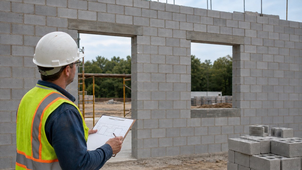
Mark each surface that closes or changes the pour. Free ends, stop ends at construction joints, steps, soffits, battered faces, curved faces, and wall intersections can create separate rows.
- A free wall end can use thickness × formed height when the end is vertical and fully formed.
- A construction-joint bulkhead follows the actual wall profile, including approved openings, waterstops, keys, or rebates.
- A wall meeting a column, beam, slab, footing, or existing wall needs one named boundary so both takeoffs do not claim the same surface.
- A sloping wall top uses the actual formed top surface when a top form is required.
- A battered face uses its accepted sloping dimension rather than an unchecked vertical projection.
- A curved wall needs inner and outer face geometry; their arc lengths differ when the wall has thickness.
RICS NRM 2 lists faces of walls, openings, wall ends, soffits, steps, sloping top surfaces, complex shapes, and wall kickers as distinct formwork items. It also requires single-sided wall work to be described.
Which length should a curved or closed wall use?
Use the contact length of each formed face. A centreline length cannot represent both faces of a curved wall unless the approved rules explicitly use that basis.
For a circular wall with centreline radius R and thickness t, the inner and outer radii are commonly R − t/2 and R + t/2 when the centreline is midway through the thickness. Multiply each accepted arc length by formed height, then handle openings and ends on that face.
At corners, tees, and closed loops, establish consistent face paths. A face-to-face dimension chain, centreline chain, or model surface schedule can produce different lengths when corner returns and wall thickness are handled inconsistently.
Why is contact area different from panel inventory?
Contact area measures the cumulative surfaces formed across the work. Panel inventory describes the assemblies present during one pour cycle.
The metric example has 45.64 m² of scheduled contact area. Dividing that number by a plywood sheet's nominal area gives only a theoretical comparison. It omits panel orientation, cuts, seams, overlaps, corners, opening frames, fillers, tie locations, walers, braces, platforms, lifting points, damaged parts, and the selected system's permitted reuse.
| Field | Record |
|---|---|
| Pour zone | Wall marks and contact area served in one cycle |
| Panel layout | Product codes, orientation, joints, corners, fillers, and opening frames |
| Connections | Ties, anchors, clamps, walers, braces, and closures from the approved design |
| Access | Platforms, ladders, guardrails, lifting, and exclusion arrangements |
| Cycle | Erection, inspection, placement, release, cleaning, repair, and next location |
| Condition | Usable, repair, reject, or hold status by component |
Reuse reduces inventory for later cycles only when the schedule, stripping criteria, condition, finish requirement, and approved system allow it. Avoid a universal reuse or waste percentage.
Can a BIM or CAD area be used directly?
Use model output after a surface-level check. The model needs correct wall joins, openings, phases, levels, face classifications, design options, and revision status.
- Freeze the model and drawing revisions used for the takeoff.
- Export wall mark, zone, length, base, top, thickness, opening, and face-area fields.
- Check one simple wall and one wall with an opening by hand.
- Inspect joined, stacked, curved, partial-depth, demolished, and future walls.
- Map model surfaces to the contract's measurement categories.
- Record manual adjustments as separate rows with reasons.
A model can calculate geometric surface area consistently while still using the wrong scope. Confirm which surfaces require formwork and which rules govern them.
What safety and design limits apply?
Area calculations do not determine fresh-concrete pressure, tie spacing, anchor loads, waler spacing, brace capacity, panel strength, placement rate, concrete temperature or consistency, vibration, wind loads, platforms, access, lifting, stripping time, or reuse approval.
For covered United States work, OSHA 29 CFR 1926.703 requires formwork to support anticipated vertical and lateral loads without failure. It also requires formwork plans and revisions at the jobsite and sets conditions for removing forms and shores. Project design, manufacturer instructions, local law, inspection, and qualified supervision control the actual system.
One-sided wall formwork can transfer loads differently from tied two-sided systems. A one-face quantity label does not authorize an earth-backed wall, existing-structure anchor, brace arrangement, or placement method.
Common wall formwork quantity mistakes
- Applying two formed faces to every wall.
- Subtracting a through-opening only once from two broad faces.
- Deducting opening face area while omitting formed jambs, heads, or sills.
- Adding all four returns when one edge is open or cast against another element.
- Missing free ends, stop ends, joints, steps, and sloping tops.
- Using wall height instead of the accepted formed lift.
- Mixing centreline and face lengths at corners and intersections.
- Using the same arc length for both faces of a curved wall.
- Applying a contract deduction rule as universal net geometry.
- Treating square metres or square feet as a panel purchase count.
- Applying a fixed waste, reuse, tie, or brace factor.
- Accepting model area without face, join, opening, phase, and revision checks.
Final measurement and release check
- Freeze the drawing, specification, model, pour-plan, and form-design revisions.
- Use the Concrete Wall Quantity Takeoff to reconcile wall marks, zones, dimensions, and openings.
- Draw and label every formed main face, opening return, wall end, and stop end.
- Calculate each compatible surface row and retain full precision.
- Apply the selected measurement rules with their exact thresholds.
- Check one simple wall and one opening or intersection independently.
- Separate gross contact area, simultaneous form sets, panel inventory, and cycles.
- Record unresolved design, supplier, safety, and site questions.
- Release the takeoff with preparer, checker, revision, and date.
Return to the Concrete planning hub for the full cluster. Use the Concrete Column Formwork Area guide for column faces and the Concrete Slab Formwork Area guide for soffits, edges, blockouts, and stop ends. The calculation methodology explains units, assumptions, and rounding, and the corrections route accepts a source or arithmetic issue.
Sources and source scope
- RICS NRM 2 supports the cited wall-face, opening, end, soffit, step, finish, curve, permanent-form, and NRM-specific deduction context.
- SCSI Agreed Rules of Measurement, Fifth Edition supports the cited wall, one-sided, wall-end, opening-edge, height, and ARM-specific opening categories.
- HKIS BIM Measurement Information Requirements supports the stated wall quantity-information fields.
- NIST Handbook 44 (2026), Appendix C supports the stated area-unit relationships.
- OSHA 29 CFR 1926.703 supports the stated United States workplace requirements.
Source scope: RICS and SCSI provide separate measurement frameworks. HKIS supports quantity-information fields. NIST supports unit relationships. OSHA supports the cited United States workplace boundary. These sources do not select the project's formed faces, opening detail, form system, panel count, allowance, reuse count, tie or brace spacing, placement rate, or stripping time.
Review note: Saleem Sial owns the research and editorial record. Formula fixtures, source checks, build validation, and rendered QA form the internal publication gate. Waseem Sial, External Reviewer and Engineer, is listed for ongoing external review; no completed review date is claimed.