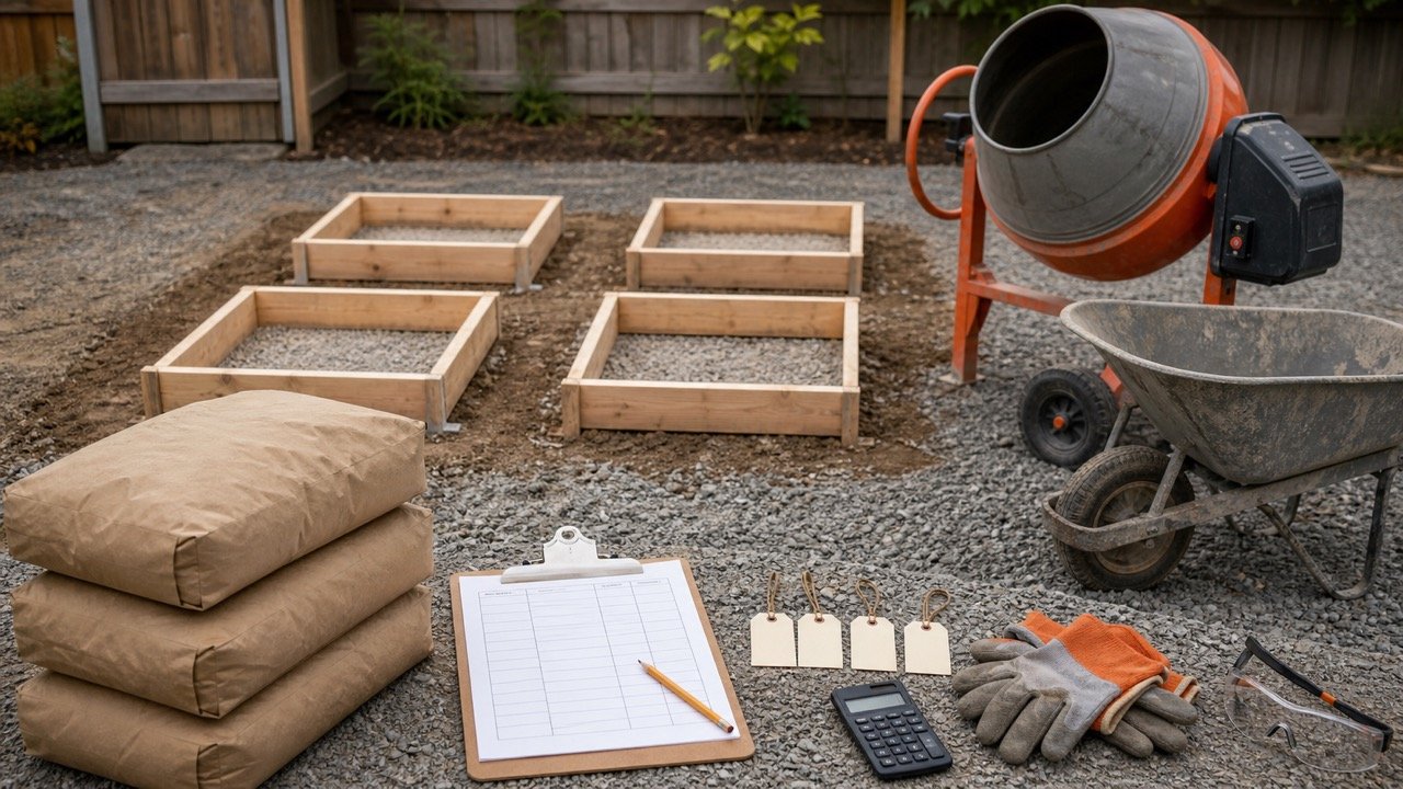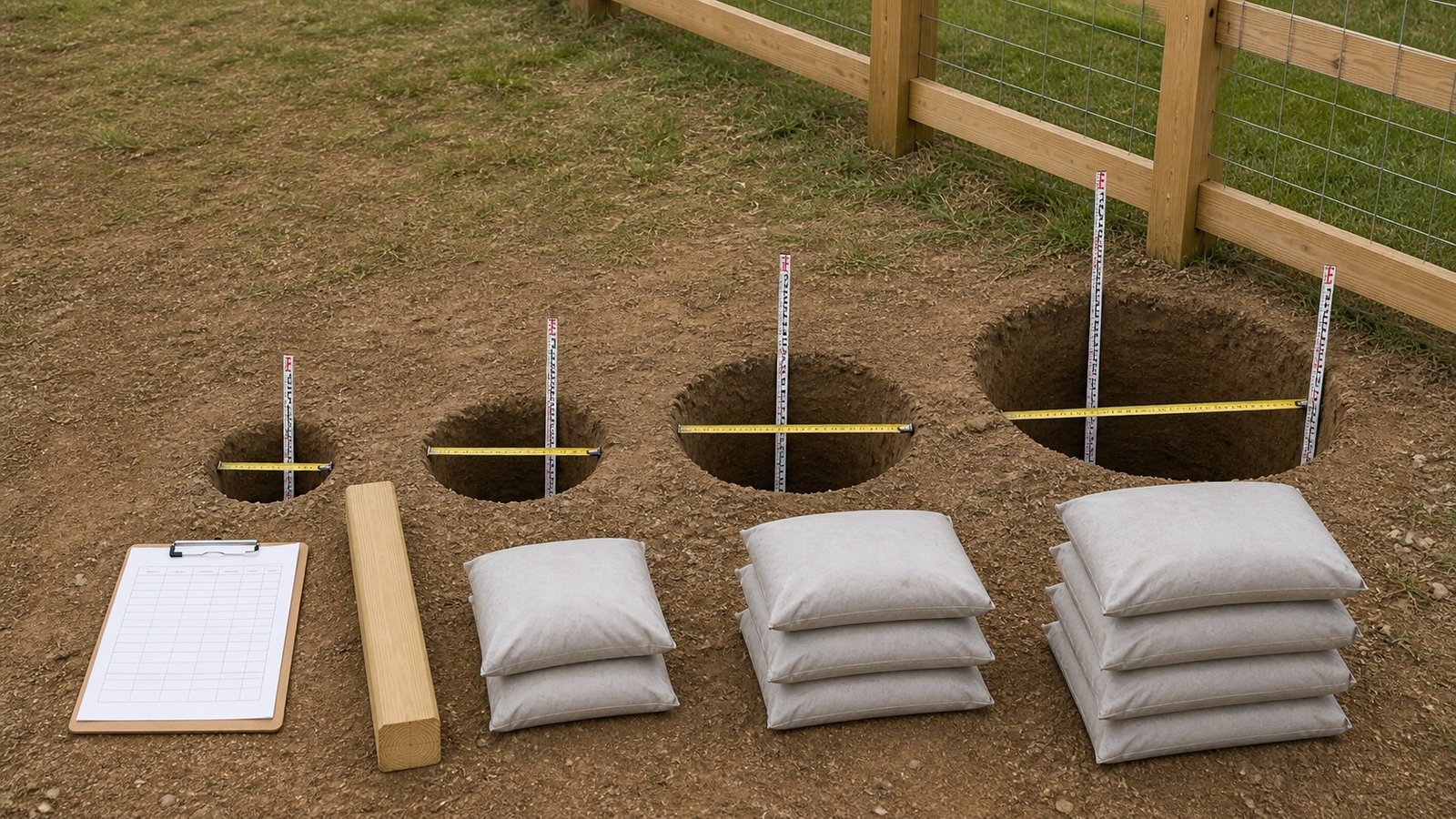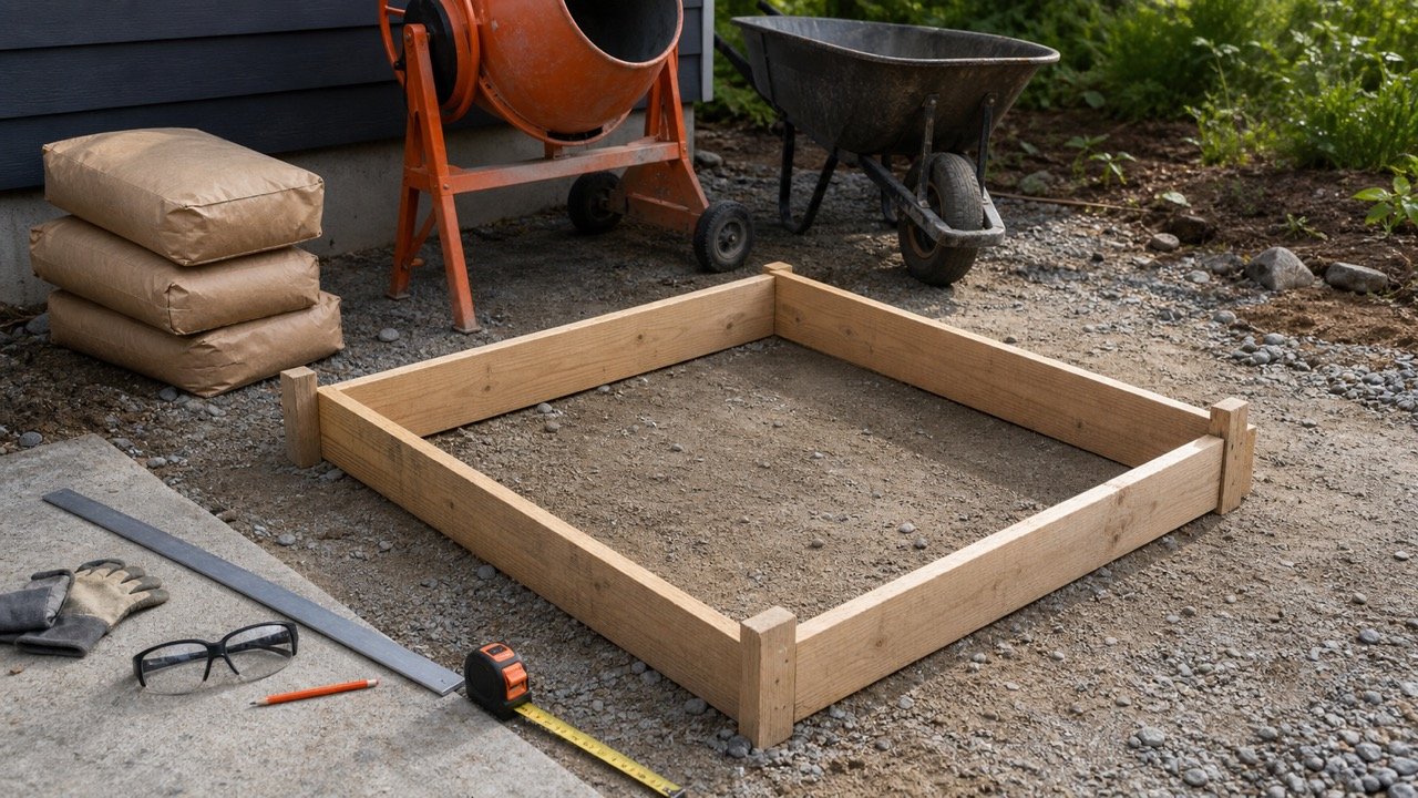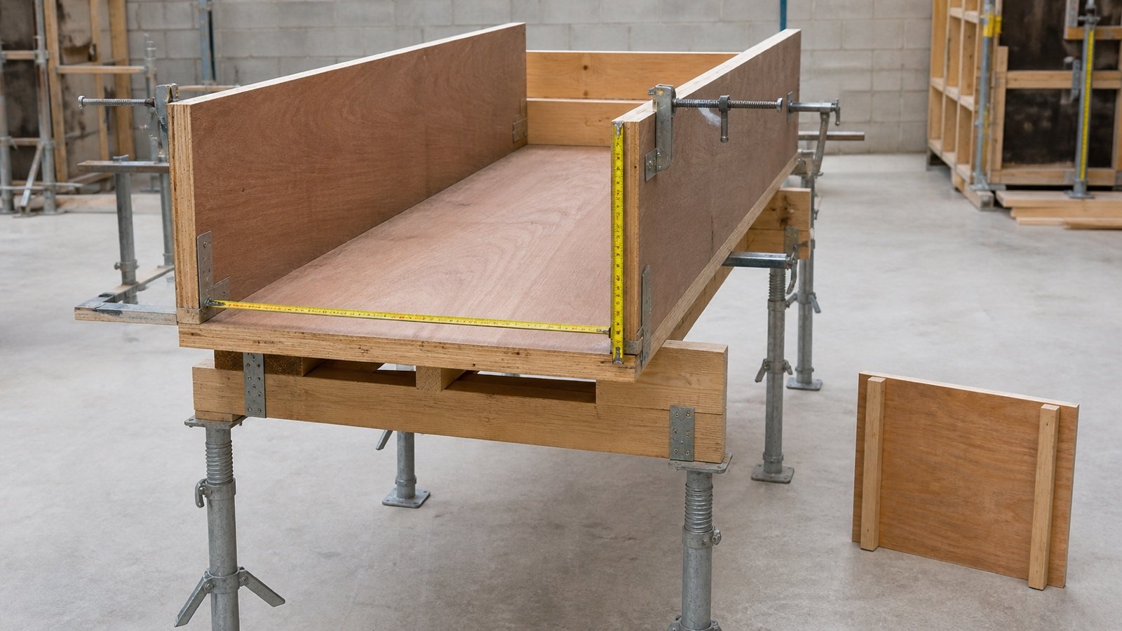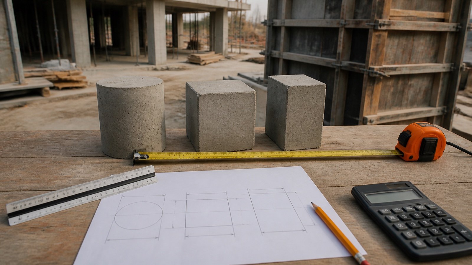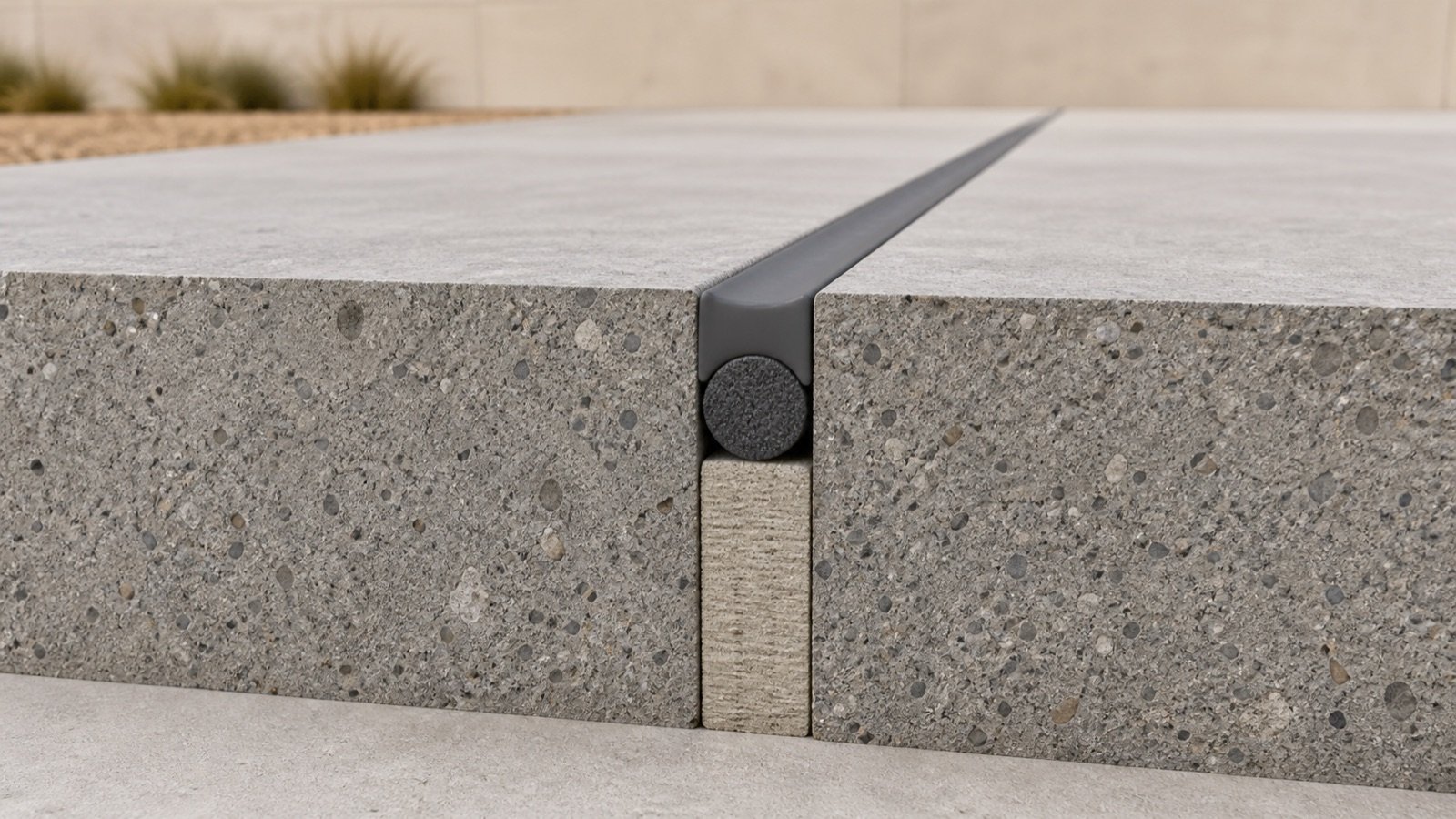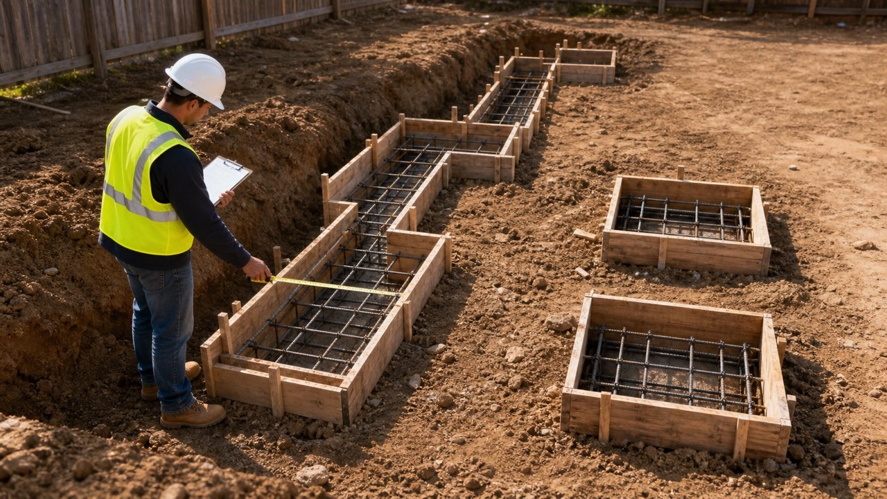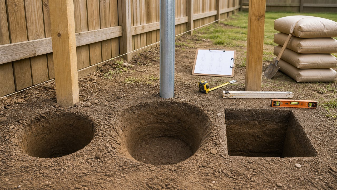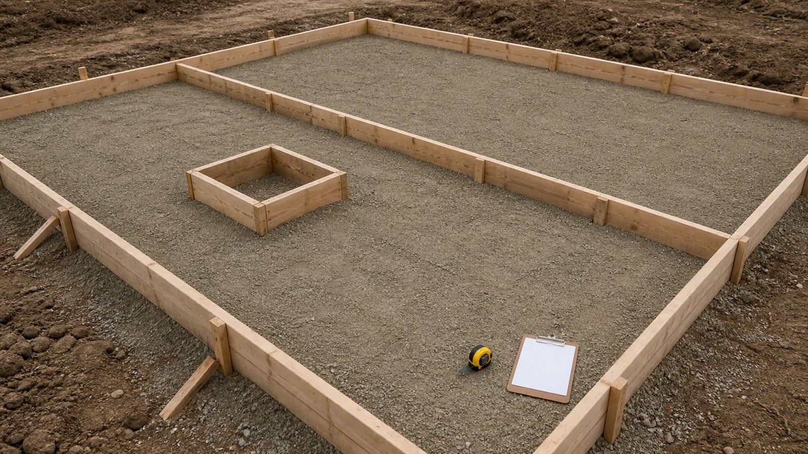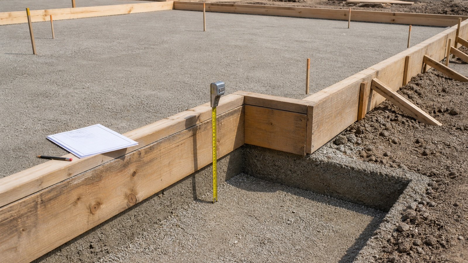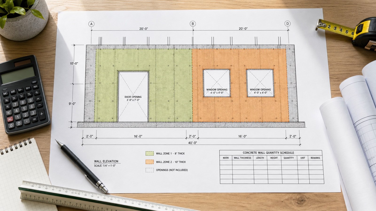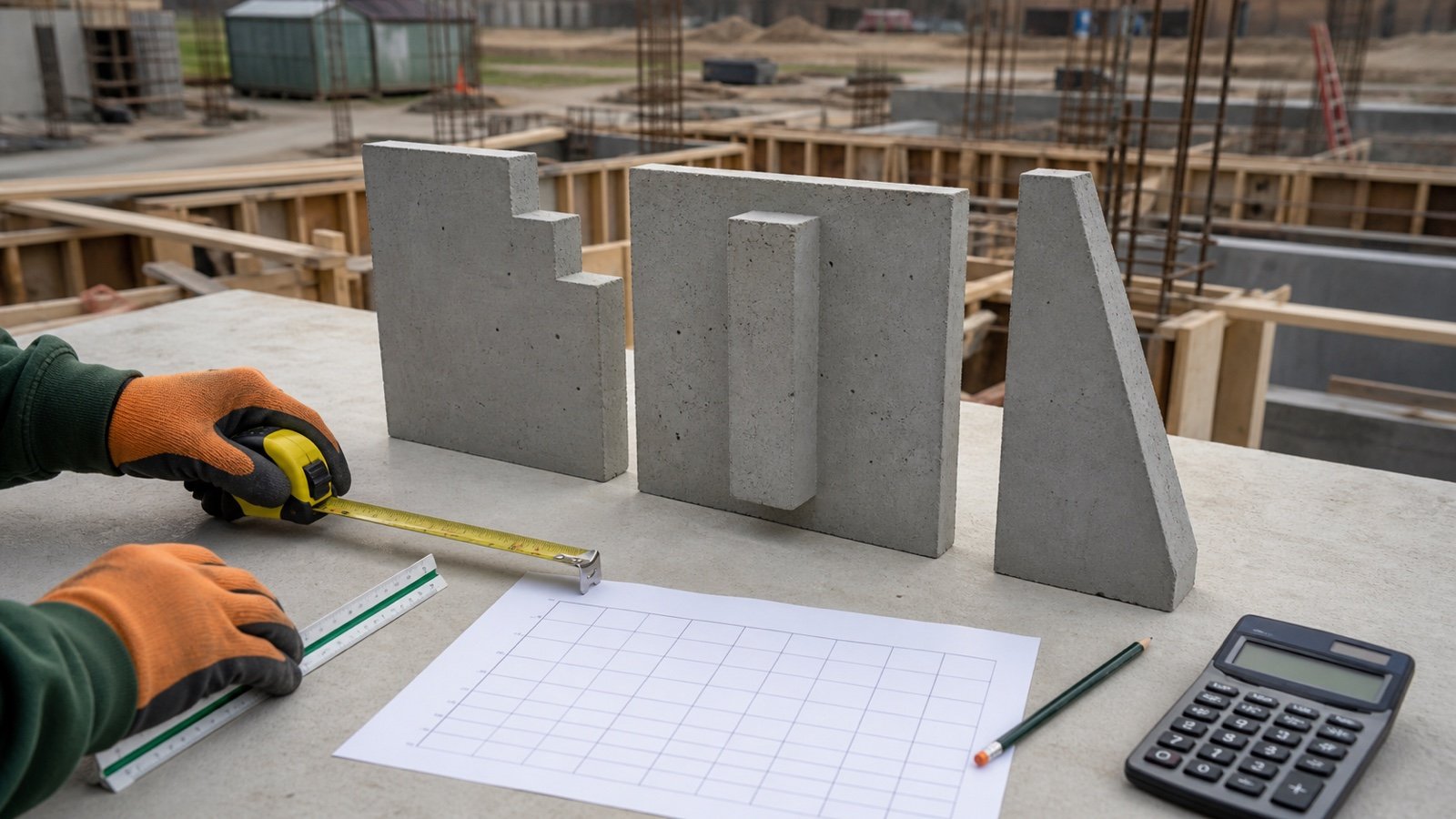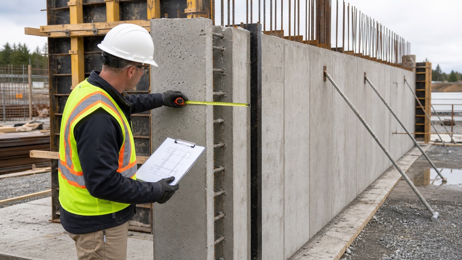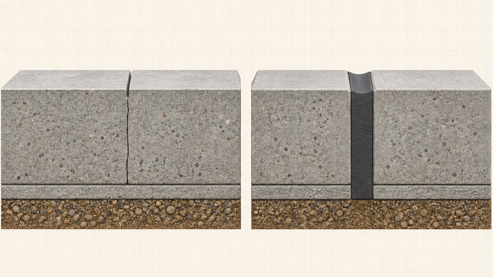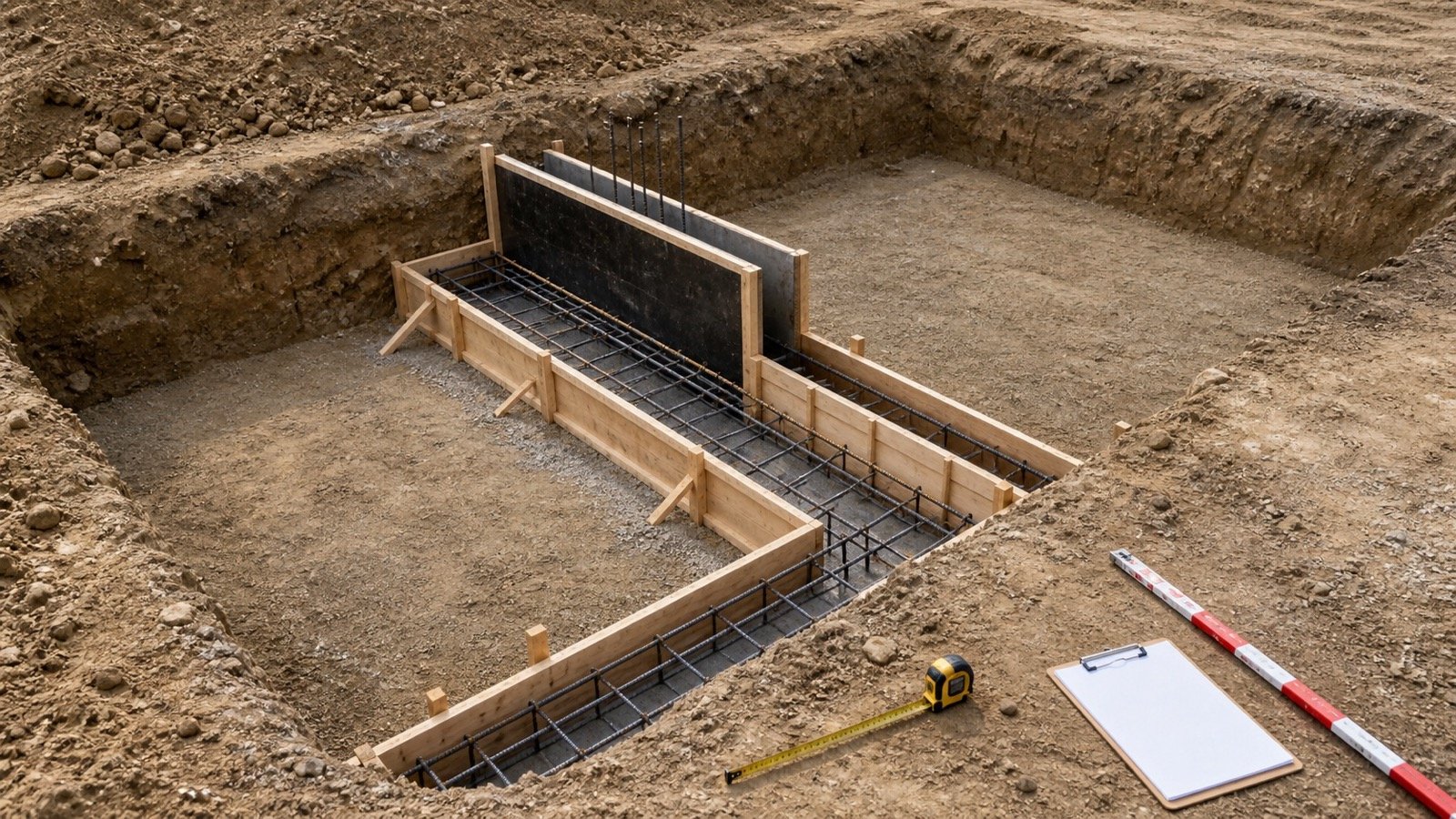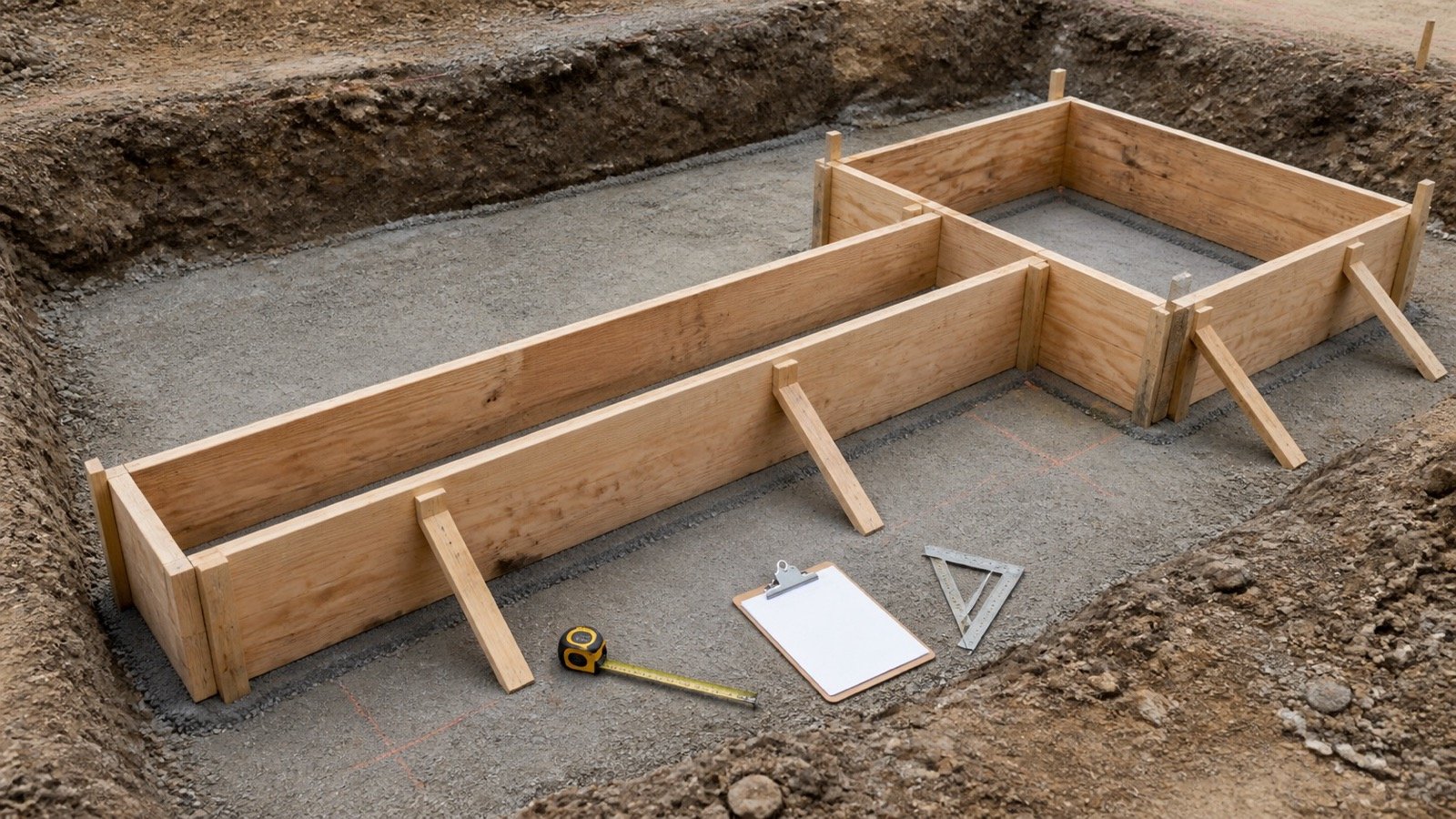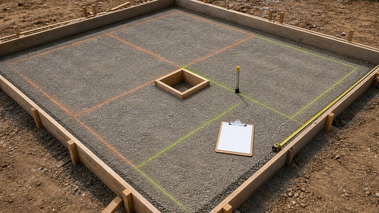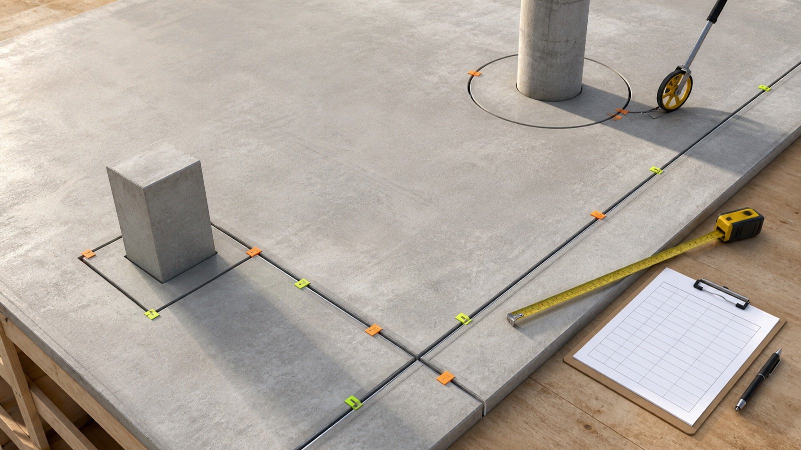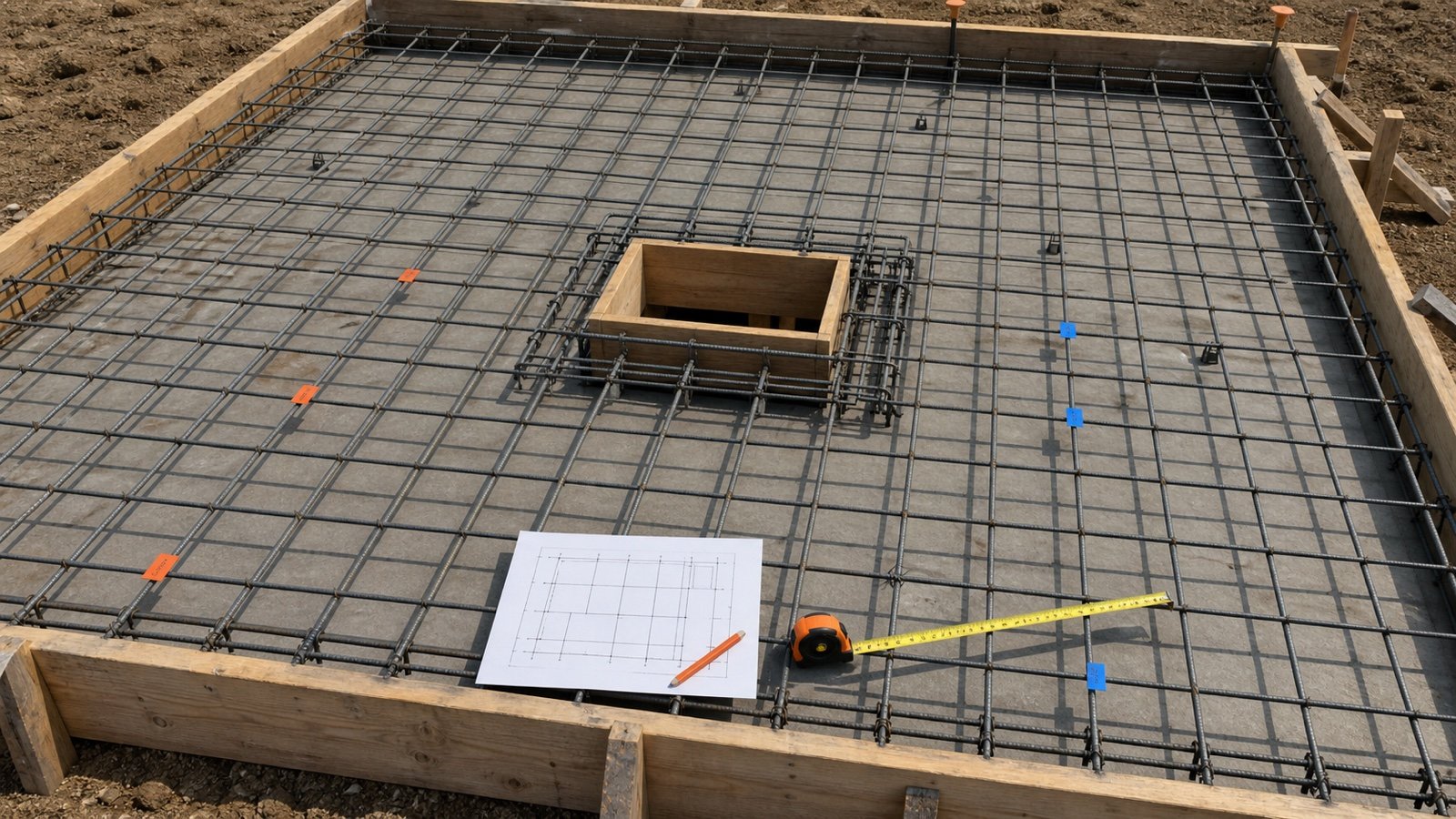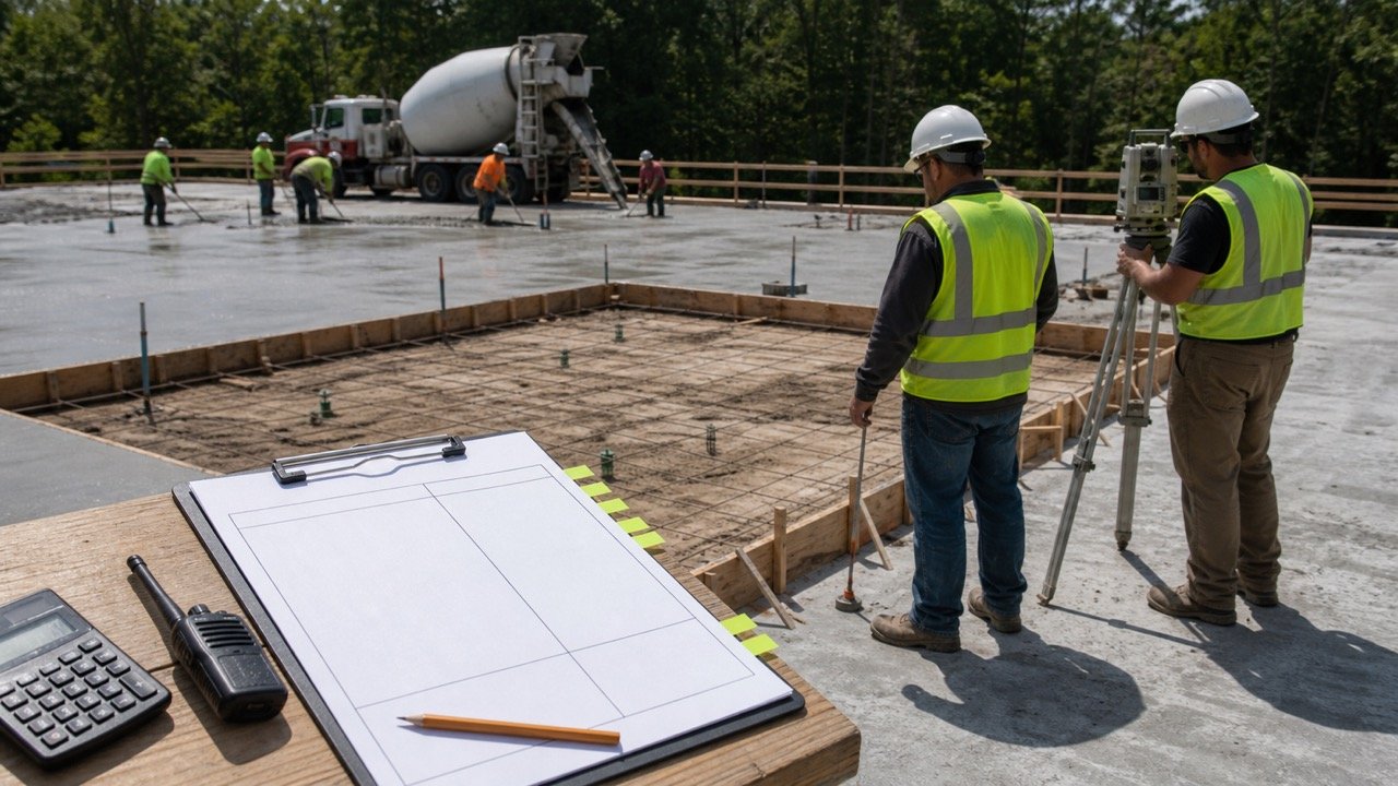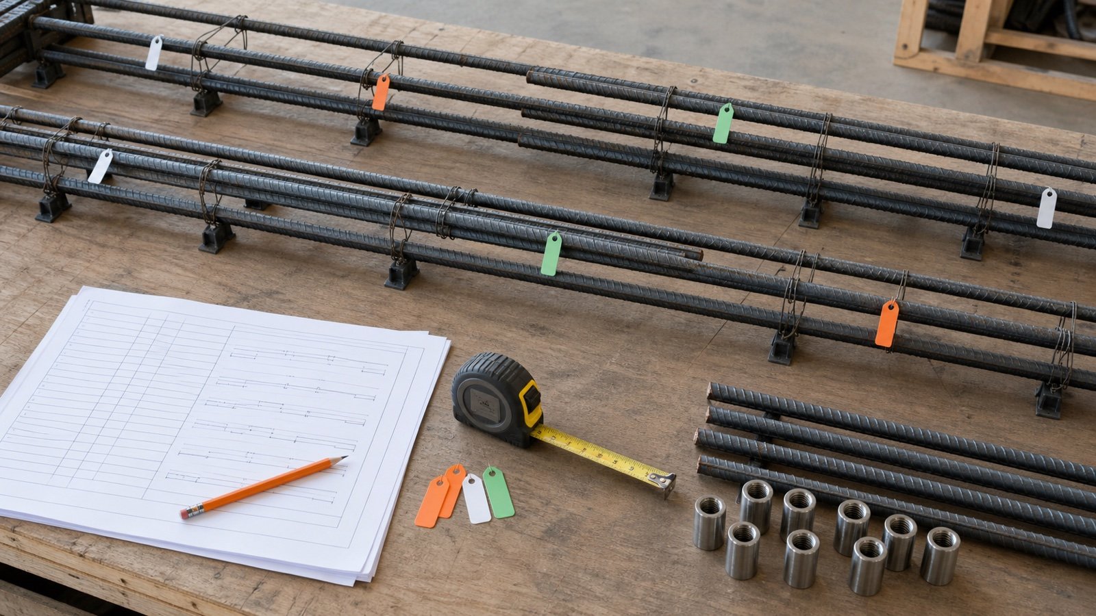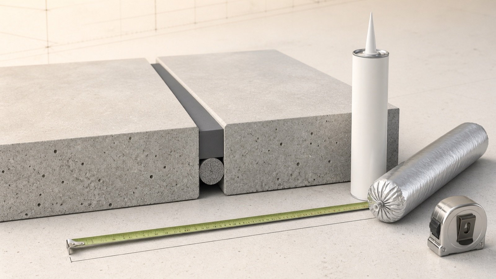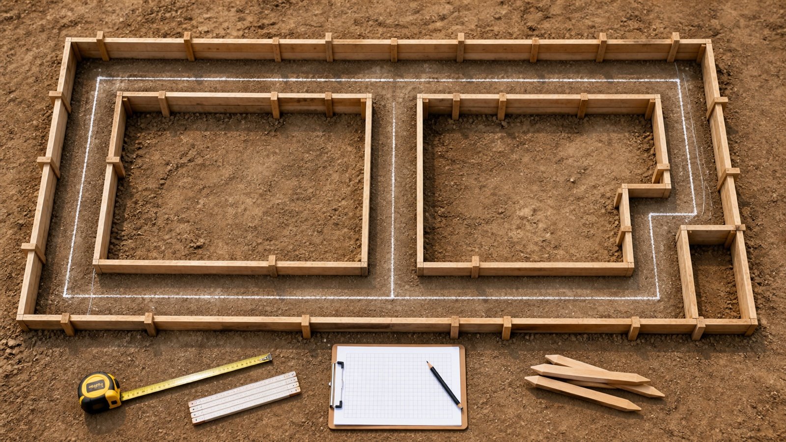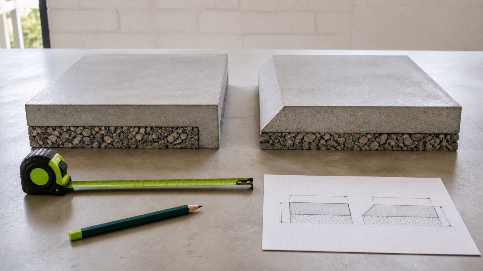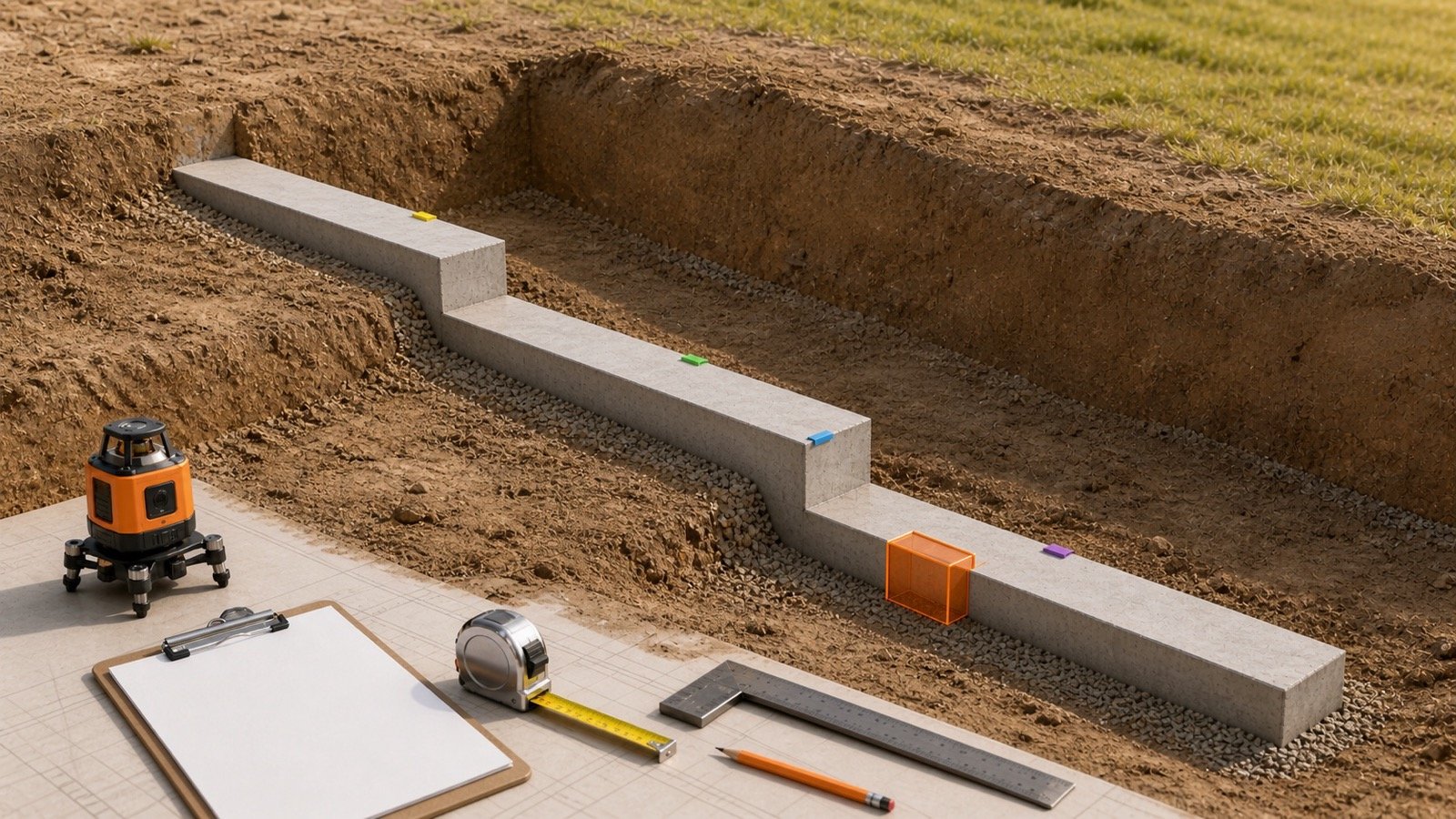
A stepped footing changes level along a slope or across approved bearing elevations. Its concrete takeoff needs section boundaries that follow the drawing, because the vertical rise can be mistaken for extra concrete or counted twice at the transition.
Build the quantity as a schedule of non-overlapping solids. Record each horizontal run with one constant width and concrete depth, then deal with any transition shape shown on the approved detail as a separate line.
How do you calculate concrete for a stepped footing?
Divide the approved footing into non-overlapping runs. Multiply the horizontal length, width and concrete depth of each run, add the run volumes, add any separately shown transition solid, and subtract only a verified duplicate volume.
Run volume = horizontal run length × footing width × concrete depth × quantity
Measured stepped-footing volume = sum of run volumes + shown transition solids − verified duplicate volume
Use compatible units before multiplying. Metres produce cubic metres. Feet produce cubic feet, which you divide by 27 for cubic yards. NIST Handbook 44 Appendix C supports the unit relationships used here; it does not select footing dimensions.
Does the vertical rise add concrete volume?
A rise changes the elevation of the next run. It adds concrete only where the approved detail shows a solid outside the rectangular run volumes already counted.
Consider two adjacent runs with the same width and depth. If their horizontal lengths meet at one vertical plane, each run remains a rectangular prism at a different elevation. The height difference alone is not another full-length volume line.
A vertical step face has area, which may affect formwork. Area has no volume until a thickness and a third dimension define a solid. Use the Footing Formwork Area guide when the task is contact area rather than concrete volume.
How should the run schedule be prepared?
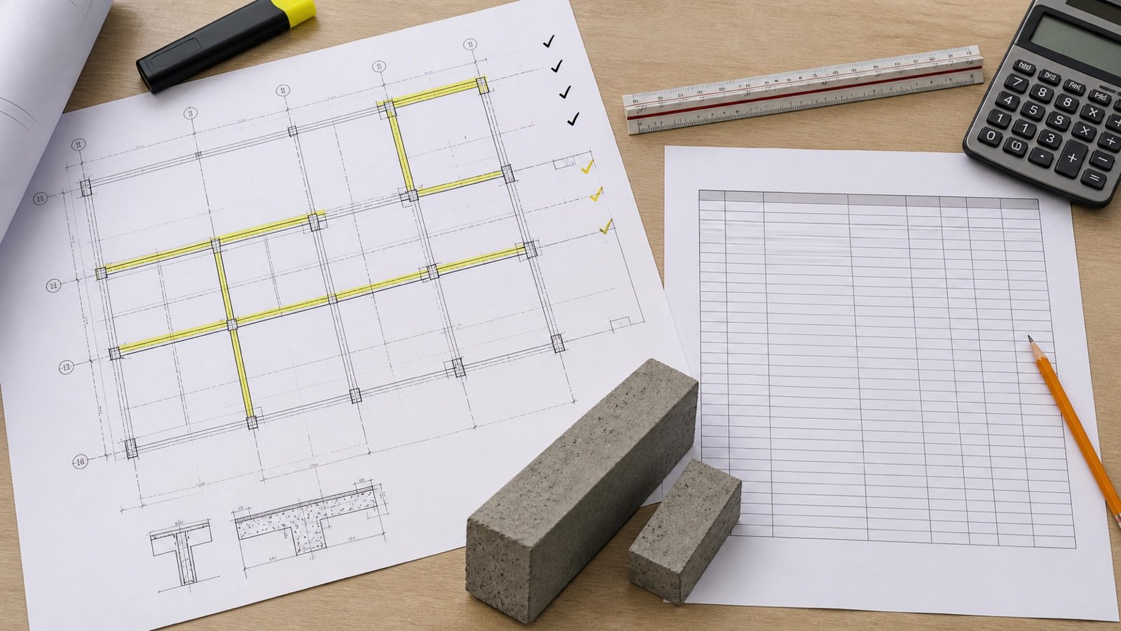
Start with the latest approved plan, section and detail. Mark a new schedule line whenever horizontal length, width, concrete depth, quantity, footing mark, revision or concrete boundary changes.
| Schedule field | What to record | Why it matters |
|---|---|---|
| Section ID | Drawing mark or a traceable takeoff label | Connects the number to one visible solid |
| Horizontal run | Plan length between non-overlapping boundaries | Prevents the slope length from replacing the concrete run |
| Width and depth | Approved concrete dimensions for that run | Separates changes instead of hiding them in an average |
| Quantity | Count of identical, separate runs | Avoids copying dimensions into unverified locations |
| Transition | Detail reference and extra solid dimensions | Shows why an addition exists |
| Deduction | Shared footprint, depth and reason | Removes only concrete counted on 2 lines |
Measure length with one stated convention. The Strip Footing Length guide explains centreline, outside, inside and clear-run methods at corners and intersections.
Worked metric example: 4 stepped runs
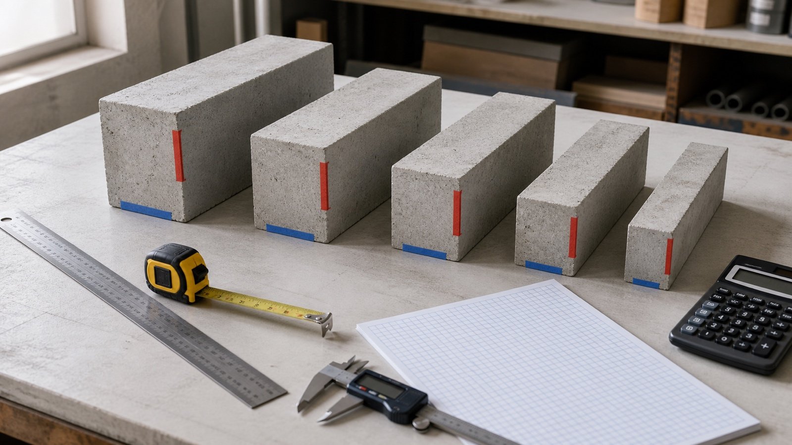
An approved takeoff has 4 non-overlapping horizontal runs. Runs A and B are 0.60 m wide and 0.25 m deep. Runs C and D are 0.75 m wide and 0.30 m deep.
| Run | Dimensions | Volume |
|---|---|---|
| A | 4.2 m × 0.60 m × 0.25 m | 0.6300 m³ |
| B | 3.6 m × 0.60 m × 0.25 m | 0.5400 m³ |
| C | 2.8 m × 0.75 m × 0.30 m | 0.6300 m³ |
| D | 1.9 m × 0.75 m × 0.30 m | 0.4275 m³ |
| Run total | 2.2275 m³ | |
The scheduled runs contain 2.2275 m³, equal to 2,227.5 L. Their changes in elevation do not alter that result.
Suppose the approved detail also identifies one extra transition block outside those base prisms. Its dimensions are 0.60 m × 0.60 m × 0.30 m, so it adds 0.1080 m³. The scenario total becomes 2.3355 m³, or 2,335.5 L.
That transition block is a worked geometry scenario. It is not a standard step, recommended size or automatic addition.
When does a transition need its own volume line?
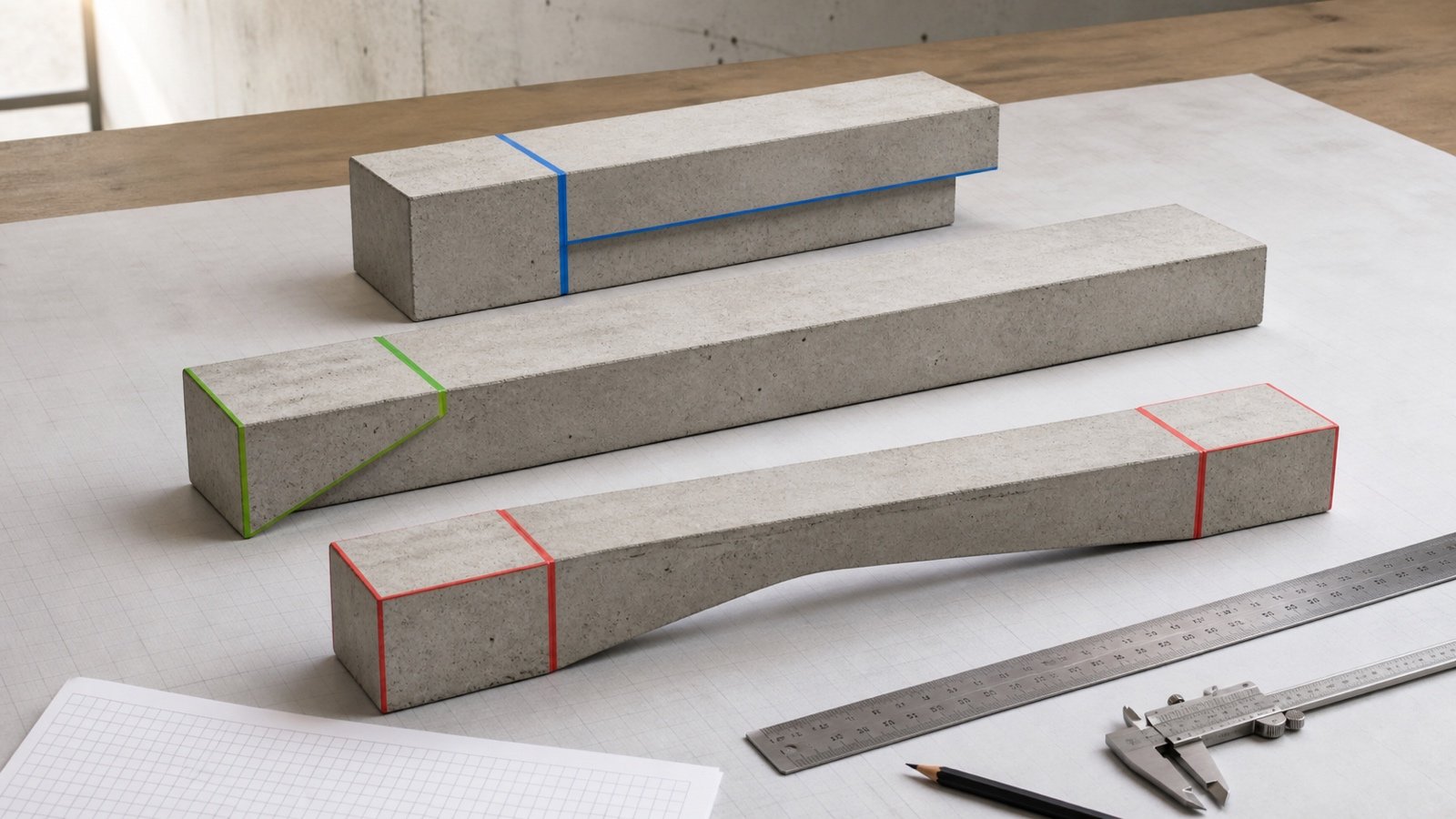
Add a transition line only when the drawing shows concrete that falls outside the scheduled run prisms. Trace the shape in plan and section before choosing its formula.
- Overlay the adjacent run boundaries on the detail.
- Shade the solids already included by length × width × depth.
- Identify any unshaded concrete at the step.
- Break that remainder into geometry the drawing actually defines.
- Record the dimensions and detail reference beside the addition.
A rectangular extra-depth block uses length × width × extra depth. A sloped, tapered or irregular transition needs the geometry specified by the approved detail. Do not approximate it as a trapezoid unless the actual section and dimensions support that shape.
Can you use the solid-stair formula?
The solid-stair expression does not describe a typical stepped strip-footing schedule. It calculates a staircase-shaped mass in which each tread includes the accumulated depth beneath it.
A stepped footing consists of approved footing runs and connection details at changing elevations. Using rise × run × width × n(n + 1) ÷ 2 can create a false volume when the concrete is a narrow strip with discrete level changes.
If the project detail defines a solid stair-shaped foundation element, calculate that stated solid. Label it accurately so it cannot be confused with a continuous strip footing.
Worked imperial example: runs plus one shown addition
An approved schedule has 3 non-overlapping runs measuring 12 ft, 9.5 ft and 7 ft. Each run is 24 in wide and 10 in deep.
- Total horizontal run: 12 + 9.5 + 7 = 28.5 ft.
- Width: 24 ÷ 12 = 2 ft.
- Depth: 10 ÷ 12 = 0.833333 ft.
- Run volume: 28.5 × 2 × 0.833333 = 47.5 ft³.
- Cubic-yard volume: 47.5 ÷ 27 = 1.759259 yd³.
The detail also shows one extra block outside the run prisms. It is 2 ft wide, 1.5 ft long in plan and 8 in, or 0.666667 ft, deeper than the base prism already counted.
The addition is 2 × 1.5 × 0.666667 = 2.0 ft³. The measured total is 49.5 ft³, equal to 1.833333 yd³. Round for reporting or ordering after the full-precision sum has been checked.
How do you prevent overlap at a step?
Draw the boundary of every scheduled solid. Two lines may touch at a plane without overlapping. A deduction is needed only when both lines contain the same physical concrete.
For example, a run and a transition line both include a 0.60 m × 0.40 m footprint through 0.25 m of depth. The duplicate is 0.0600 m³. Deduct it once, or redefine the transition as extra depth only so the overlap never enters the schedule.
The second approach often produces a clearer audit trail. It records the base prism on the run line and only the incremental solid on the transition line.
How should drawing revisions and field changes be recorded?
Keep the original section schedule and add a dated revision. Identify the affected run, old dimensions, new dimensions, volume difference, reason and approval reference.
If Run C in the metric fixture changes from 2.8 m to 3.1 m, its new volume is 3.1 × 0.75 × 0.30 = 0.6975 m³. The increase is 0.0675 m³. Updating one identified line preserves the reason for the changed total.
Field overbreak, collapsed soil, water, loose material or a changed bearing level needs site action and a recorded decision. Hiding an unknown condition inside a percentage removes the link between the physical change and the quantity.
Which quantities stay separate from footing concrete?
Keep excavation, blinding, footing concrete, walls, pedestals, grade beams, formwork, reinforcement and backfill as separate takeoff items. They can share boundaries without sharing the same formula or unit.
Excavation may include working room, sloping, benching, a protective system, drainage or overdepth. Compare those volumes with the method in Footing Excavation vs Concrete.
A step face can add formwork contact area while adding no separate concrete volume. Reinforcement lengths and laps follow approved structural details and remain outside this geometric volume guide.
Should a waste or planning allowance be added?
Start the measured volume at 0% allowance. Add a separate planning percentage only when drawings, specifications, measured tolerances, accepted field conditions, placement method or an approved takeoff policy provides its basis.
Keep measured and planning totals visible together. An allowance cannot correct a missing run, mixed units, a duplicated transition, an unknown detail or an unsafe excavation.
Supplier order increments, minimum deliveries and mixture requirements also sit after the measured quantity. Use current producer terms when the volume becomes a ready-mix order.
Common stepped-footing takeoff mistakes
- Using the slope distance instead of the horizontal run shown for the footing.
- Adding the full vertical rise as another concrete prism.
- Applying a solid-stair formula to a narrow strip footing.
- Using one average depth across discrete runs.
- Counting both sides of one step boundary as overlapping length.
- Adding a transition block that the run prism already includes.
- Entering centimetres as metres or inches as feet.
- Rounding every line before summing the schedule.
- Using excavation width as concrete width.
- Combining the footing, wall, pedestal and blinding in one line.
- Applying a fixed allowance without a recorded basis.
- Treating the quantity result as approval of the footing design.
What design and excavation limits apply?
The approved designer and authority determine the step configuration. Soil or rock, loads, bearing level, groundwater, frost, nearby foundations, ground movement and slope stability can affect the footing. The FHWA lists these factors in its noise-barrier foundation context and notes that stepped footings may suit grade changes. That handbook does not provide a universal building detail.
The City of Santa Clarita and City of San Clemente sheets show local stepped-footing details from 2015. Santa Clarita expressly states that its sheet does not replace a complete set of plans. Neither sheet proves a current rule for another place or project.
For covered U.S. construction work, OSHA 29 CFR 1926.651 addresses utilities, access, water accumulation, adjacent structures, loose material and inspections within its scope. Use the current requirements, project controls and a competent person where applicable. This page does not design an excavation or protective system.
What should the final quantity record contain?
- Project, footing mark, drawing and detail revisions, takeoff date and checker.
- Run IDs, horizontal lengths, widths, concrete depths, quantities and units.
- Transition geometry, detail reference and proof that it lies outside the run prisms.
- Any duplicate deduction with its footprint, depth and reason.
- Measured total before allowance, chosen allowance and documented basis.
- Field revisions, unresolved conditions and approval references.
- Supplier handoff, order increment and delivery basis when ordering begins.
Enter up to 4 checked section lines in the Concrete Footing Calculator. It keeps the gross schedule, verified intersection deduction, measured volume and optional planning allowance separate.
For the broader workflow, read Concrete Footing Volume. Return to the Concrete Planning hub for bag, ready-mix and related quantity tools.
Sources and scope
- NIST Handbook 44, 2026, Appendix C: metric and U.S. customary unit relationships used in the fixtures.
- OSHA 29 CFR 1926.651: cited U.S. excavation requirements within its scope.
- FHWA Noise Barrier Design Handbook, Section 8: foundation-condition factors and stepped-footing context for noise barriers.
- City of Santa Clarita Typical Stepped Footing Detail and City of San Clemente Detail BI-8: local detail examples and issuing context.
Source scope: NIST supports unit relationships. OSHA supports the stated U.S. workplace boundary. FHWA and the city sheets illustrate conditions and local details within their stated scopes. They do not choose project dimensions, step geometry, reinforcement, concrete mixture, allowance, supplier increment or price.
Review note: Saleem Sial owns the research and editorial record. Formula fixtures, source checks, build validation and rendered QA form the internal publication gate. Waseem Sial, External Reviewer and Engineer, is listed for ongoing external review; no completed review date is claimed.