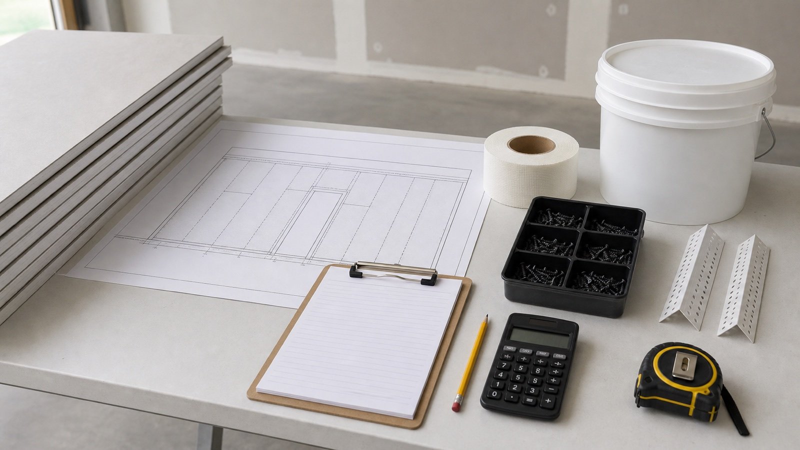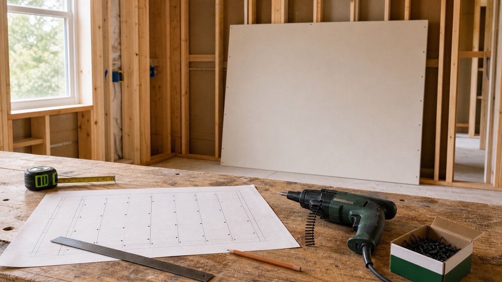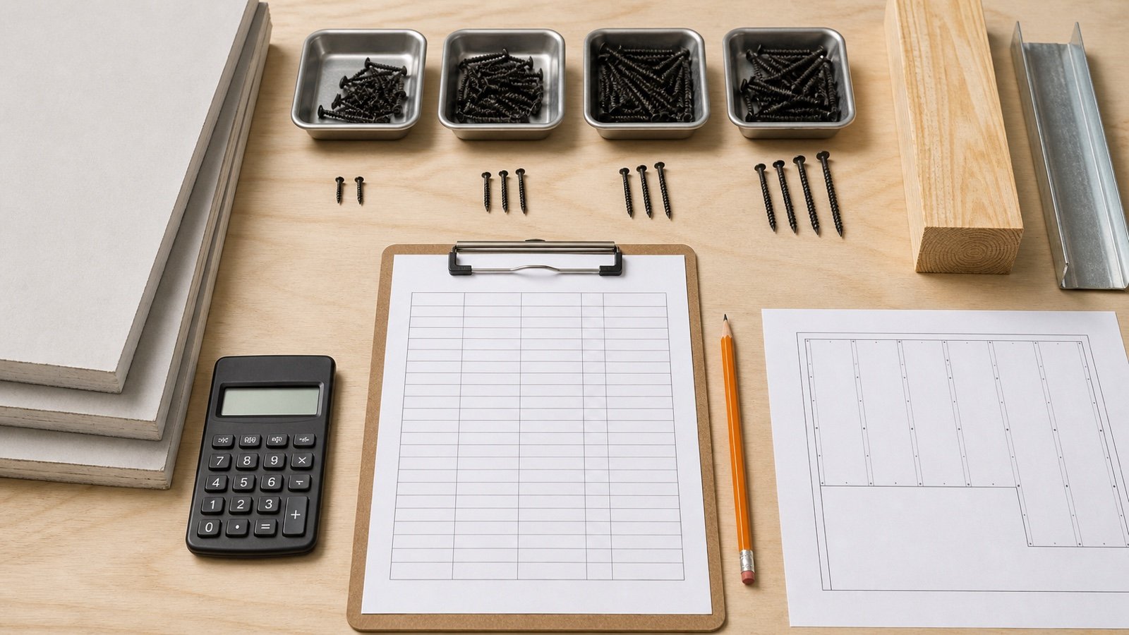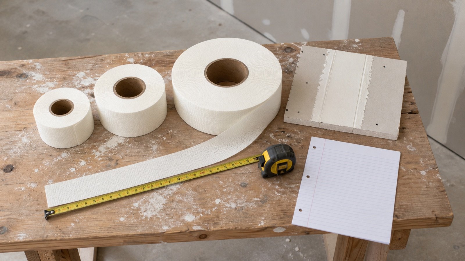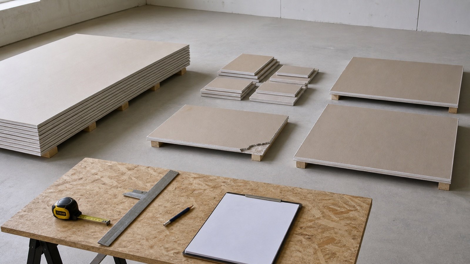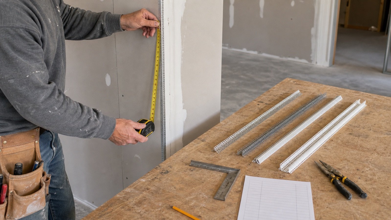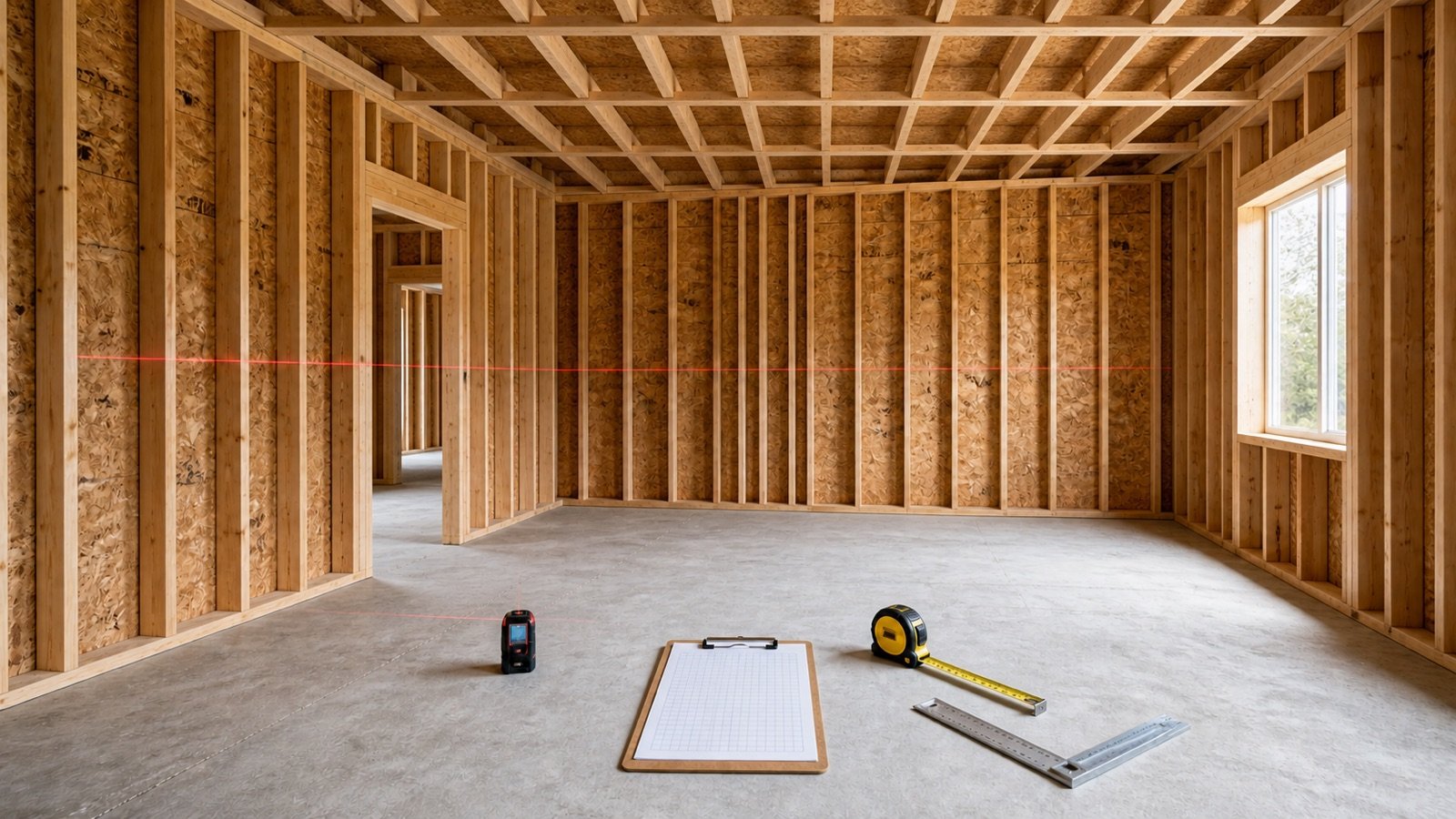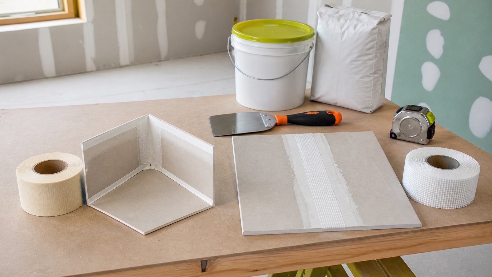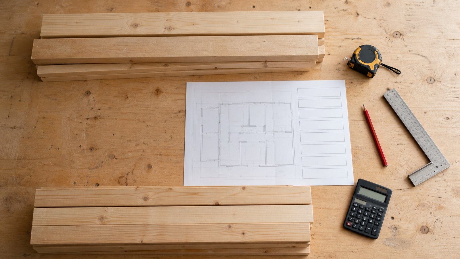
Drywall tape quantity depends on the joints that the accepted panel layout creates. Record each taped run by location, measure its centerline once and keep flat joints, inside angles and special details on separate rows.
A joint ledger gives the Drywall Tape Calculator a traceable input. It also lets another person find a missed run, a duplicate line or a layout change before tape becomes a purchase order.
How do you measure drywall joints for tape?
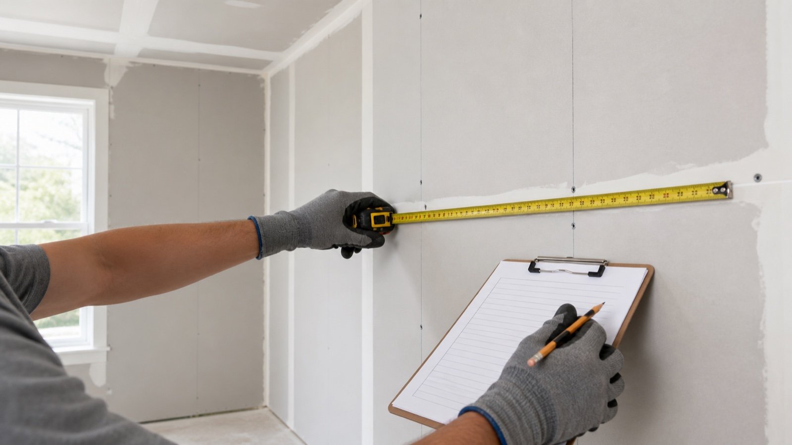
Mark every panel-to-panel joint and taped inside angle on the accepted wall and ceiling layouts. Measure the centerline length of each continuous run, multiply only identical repeated runs, and add the accepted rows.
- Assign a room, wall elevation or ceiling-zone ID.
- Draw the installed or accepted panel boundaries on that surface.
- Trace each flat or butt joint from one endpoint to the other.
- List inside wall corners and wall-to-ceiling angles that receive the selected tape system.
- Record repairs and other specified taped details as separate rows.
- Exclude boundaries handled by base trim, corner bead, control-joint accessories or another approved detail.
- Add the rows and send the base length to the calculator.
Row total = joint centerline length × number of identical runs
Base tape length = flat and butt joints + taped inside angles + other approved taped runs
What should a drywall joint ledger contain?
A useful ledger ties each length to a physical location and a treatment decision. A total written as “174 ft” cannot show whether it includes ceiling seams, wall-to-ceiling angles or an outside-corner product.
| Field | Record | Check |
|---|---|---|
| Location | Room, wall elevation or ceiling zone | Matches the current drawing or field sketch |
| Joint class | Tapered, butt, inside angle or special detail | Uses the specified treatment |
| Endpoints | Grid line, corner, opening or panel-edge references | The run can be found again |
| Length | Measured centerline length in ft or m | One unit system per total |
| Quantity | Number of identical runs represented | Dimensions and treatment repeat |
| Product row | Paper, fiberglass or named proprietary tape | Compatibility record is attached |
| Status | Accepted, field changed or unresolved | Only accepted rows enter the order |
| Revision | Drawing, layout or field-check date | The current layout controls the total |
The drywall material takeoff worksheet carries the accepted tape total into the wider sheet, compound, fastener and trim order.
Which joints belong in the tape total?
Count panel-to-panel joints and interior angles that the selected system requires you to tape. Keep product-specific trims and untreated boundaries outside the ordinary joint-tape row.
| Boundary | Tape-ledger treatment | Reason |
|---|---|---|
| Tapered-edge joint | Measure once along the joint centerline | Two panel edges create one joint |
| Butt joint | Measure once along the joint centerline | End edges still form one taped run |
| Inside wall corner | Count when the specified system uses joint tape | Paper tape commonly folds at its center crease |
| Wall-to-ceiling angle | Count when the finish and assembly require tape | The treatment can differ at a trim, reveal or movement detail |
| Outside corner | Use the selected bead or trim record | Stock length and treatment belong to that corner product |
| Floor boundary | Follow the approved base and finishing detail | The panel edge may be hidden and untreated |
| Control or movement joint | Use the project detail and accessory schedule | Ordinary tape cannot replace the specified joint |
| Repair patch | Measure the repair detail that requires tape | Patch shape and method control the run |
Why should a shared joint be counted once?
Drywall tape follows the joint centerline. Two board edges meet at that line, so adding both edge lengths doubles the material.
Sheet perimeter can provide a rough early estimate only after boundary edges and shared edges receive the correct treatment. A room perimeter, floor edge or opening edge may not receive ordinary joint tape. Build the count from installed joints when the layout is available.
Use panel-edge references to locate the run, then record the shared centerline once. Keep another row only when the project requires another taped layer or a separate product application.
How can a rectangular panel grid check joint length?
A full rectangular grid gives a quick arithmetic check before openings, staggered joints and partial pieces change the layout. Count internal row and column boundaries, excluding the outer perimeter.
Grid joint length = (columns − 1) × surface height + (rows − 1) × surface length
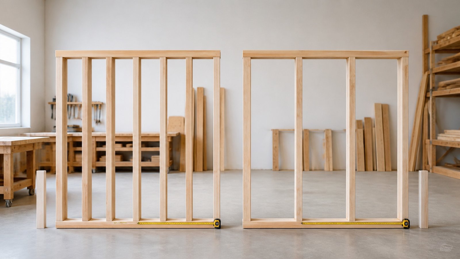
A 12 ft by 8 ft wall covered with three 4 ft-wide vertical panels has 2 internal joints. Each runs 8 ft, so the flat-joint total is 16 ft.
A basic horizontal grid on the same wall uses two 4 ft-high rows and two 8 ft-long columns. Its internal boundaries total (2 − 1) × 8 + (2 − 1) × 12 = 20 ft. The wall area stays 96 ft², while the simple grid check changes by 4 ft.
USG J371 states that panels may run horizontally or vertically and says horizontal application with 12 ft panels can reduce joint footage on walls. The same guide calls for staggered vertical joints in its wall method and advises avoiding vertical joints directly above or below openings. Use the accepted layout after those decisions, since a grid alone cannot place staggered segments.
Worked example: measuring a 12 ft by 10 ft room
This example uses 8 ft-high walls, vertical 4 ft-wide wall panels and a 4 ft by 8 ft rectangular ceiling grid. The room has no openings. All 4 vertical inside corners and the wall-to-ceiling angle receive the selected tape system.
| Location | Calculation | Tape length |
|---|---|---|
| Two 12 ft walls | 2 walls × 2 joints × 8 ft | 32 ft |
| Two 10 ft walls | 2 walls × 2 joints × 8 ft | 32 ft |
| 12 ft × 10 ft ceiling grid | (2 − 1) × 10 + (3 − 1) × 12 | 34 ft |
| Vertical inside corners | 4 × 8 ft | 32 ft |
| Wall-to-ceiling angle | 2 × (12 + 10) | 44 ft |
| Base tape | 32 + 32 + 34 + 32 + 44 | 174 ft |
Enter 174 ft in measured-joints mode. A documented 5% allowance gives 174 × 1.05 = 182.7 ft. With a declared 250 ft roll, the calculator returns 1 whole roll and 250 − 182.7 = 67.3 ft of purchase remainder.
The example explains arithmetic, not panel-layout approval. Framing, openings, panel direction, joint staggering, finish details and tested assembly requirements can change the rows.
How does an area-rate check compare with the measured ledger?
Use a named area rate as an independent comparison. Preserve the product, qualifier, reference area, market and retrieval date so the check does not become a universal constant.
The example room has 352 ft² of wall surface and 120 ft² of ceiling surface, for 472 ft² of board area. USG's J780A submittal states approximate coverage of 370 ft of its named fiberglass drywall tape per 1,000 ft² of gypsum panels.
472 ft² × 370 ft ÷ 1,000 ft² = 174.64 ft
The measured ledger gives 174 ft, a difference of 0.64 ft. That agreement checks this one fixture. Another room can have the same board area and more returns, shorter walls, openings or changed panel lengths, which can move the measured result away from the approximate rate.
How should openings and partial panels be recorded?
Draw the installed joint path around each opening. Area subtraction cannot identify the cut pieces or seam endpoints created by a door, window, access panel or service opening.
USG J371 advises avoiding vertical joints directly above or below openings in the wall method it describes. That layout choice can move a joint to another stud line and change butt-joint segments. Record the revised endpoints instead of subtracting the opening perimeter or a standard door allowance.
- Split a continuous line where the joint stops at an opening.
- Add the new joint segment where a filler or return meets another panel.
- Keep opening trim and corner products in their own material rows.
- Mark a field change with its date and drawing or sketch reference.
How should inside angles and outside corners be separated?
Measure inside angles only when the selected joint system uses tape there. USG J371 shows paper tape folded along its center crease and embedded at inside corners. USG J2140 also identifies paper tape for corners and wall-to-ceiling intersections within its product scope.
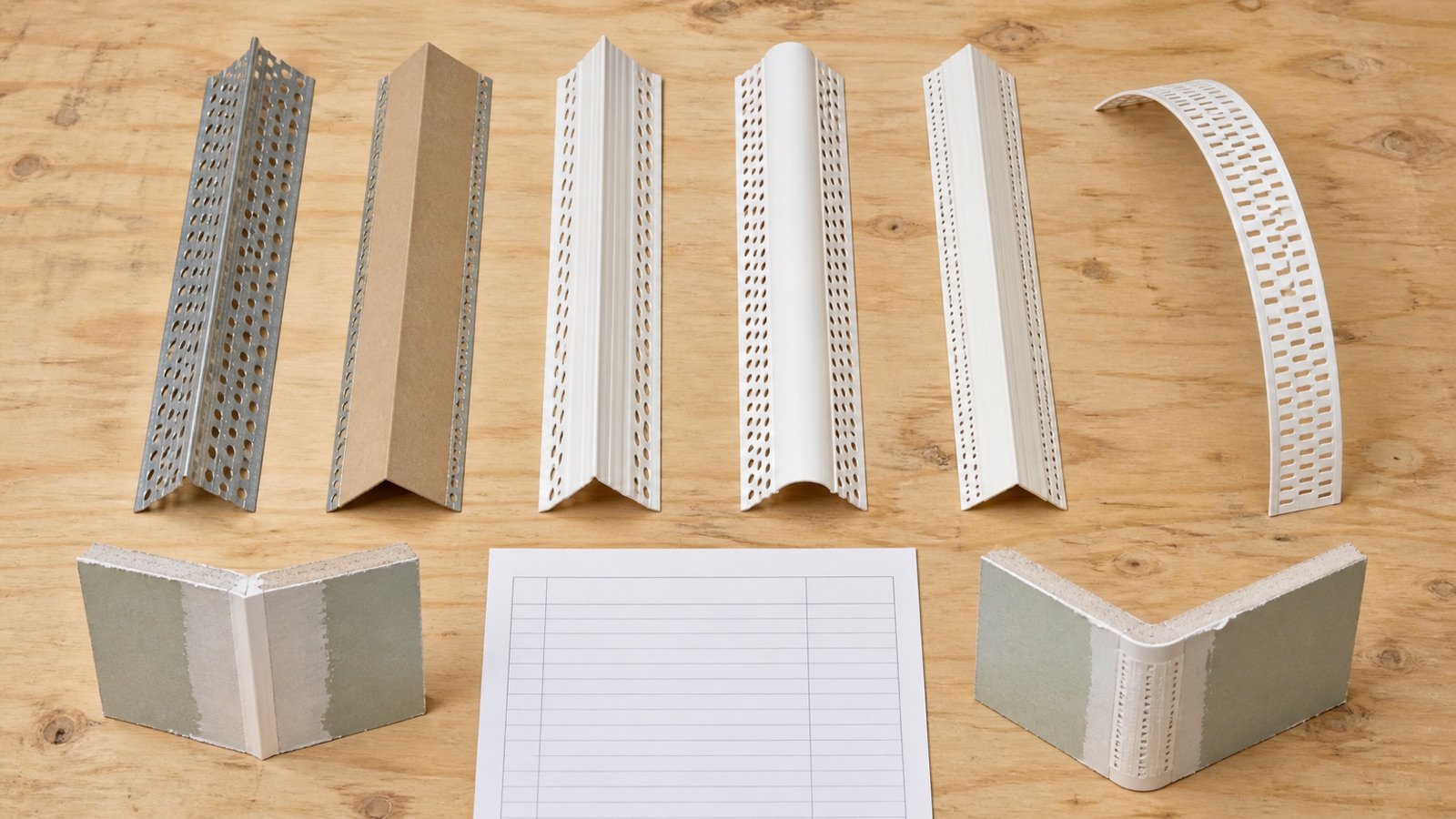
Outside corners often use metal, vinyl, paper-faced or composite bead. Measure those corner lengths for the chosen product and stock size. Add them to an ordinary joint-tape total only when the current product instructions require the same tape.
How should several tape products or board layers be scheduled?
Use one ledger and one roll calculation per tape product. Paper tape, fiberglass tape and proprietary corner products can have different package lengths and compound requirements.
For multilayer construction, follow the accepted assembly and product documents to identify which joints receive treatment on each layer. Record each treated layer by face and product. A simple board-area multiplier cannot show whether base-layer joints, face-layer joints or perimeter details require the same treatment.
USG J2140 reports product-specific differences between paper and fiberglass tape with drying-type and setting-type compounds. Its findings do not approve another manufacturer's combination or a project substitution.
How can field changes be reconciled?
Keep the original accepted length and each added or removed joint as separate entries. The revised total should close through arithmetic that another person can reproduce.
Revised base tape = accepted base + added taped runs − removed taped runs
| Revision field | Example |
|---|---|
| Original joint | C2 ceiling seam, 10 ft |
| Change | Access opening interrupts 2 ft and adds two 1 ft returns |
| Removed length | 2 ft |
| Added length | 2 × 1 ft = 2 ft |
| Net change | 0 ft, with a changed joint pattern |
| Evidence | Field sketch, date and checker |
A zero net length does not mean the record can be skipped. The changed pattern can affect tape pieces, compound work and the next layout review.
Which measurement errors change the tape order?
- Counting both panel edges at one shared joint.
- Adding the outside perimeter to every sheet.
- Using room floor area as the drywall surface area.
- Assuming equal board area creates equal seam length.
- Counting a floor boundary hidden by the approved base detail.
- Adding outside corners to ordinary tape without checking the corner product.
- Missing wall-to-ceiling angles or counting an untaped reveal.
- Using the simple grid after openings, staggered joints or partial pieces change it.
- Combining feet and metres in one total.
- Combining tape products with different roll sizes.
- Applying allowance before duplicate rows are removed.
- Refreshing the ledger total without recording the layout revision.
What should you check before calculating tape rolls?
- Every wall and ceiling zone has an accepted panel layout or field sketch.
- Each taped centerline appears once.
- Flat joints, butt joints, inside angles and special details have separate classes.
- Opening and partial-panel changes have measured endpoints.
- Outside corners, control joints and trims use their own product records.
- Each tape product has its own subtotal and current roll length.
- The unit system is consistent and conversions remain traceable.
- An entered allowance has a stated reason.
- The prepared-by, checked-by and revision fields are complete.
Send each accepted product subtotal to the Drywall Tape Calculator. Use the Drywall Calculator and wall and ceiling measurement guide when surface dimensions or panel grids still need review.
Project and product limits
Joint measurement does not select a tape, compound, finish level, corner accessory, control joint or tested assembly. Confirm current drawings, specifications, manufacturer instructions and local requirements before ordering or installation.
NIST gives the exact relationship 1 ft = 0.3048 m. Convert every length in a row before addition and round the reported total after summing. A converted 250 ft roll length equals 76.2 m, though that conversion does not prove a 76.2 m product is stocked in the local market.
Return to the Drywall planning hub for the current sheet, tape and compound workflow. The calculation methodology explains unit and rounding checks. Send a source or formula issue through the corrections route.
Sources and source scope
- USG Sheetrock Brand Installation and Finishing Guide J371 supports its horizontal and vertical application notes, reduced-joint statement for long horizontal panels, opening-related joint placement and treatment of butt, tapered and inside-corner joints.
- USG Sheetrock Fiberglass Drywall Tape J780A supports the named approximate 370 ft per 1,000 ft² coverage record, roll lengths, compatibility and market limits.
- USG Matching Joint Compound with the Proper Joint Tape J2140 supports paper and fiberglass tape distinctions, named compatibility findings and paper tape at interior angles.
- NIST Handbook 44, 2026 Appendix C supports the exact length conversion.
Source scope: USG sources cover their named products and installation context. NIST supports unit conversion. They do not approve this example layout, a universal allowance, another manufacturer's system, local stock or a project quantity.
Review note: Saleem Sial owns the research and editorial record. Source checks, independent fixtures, editorial review, build validation, link crawl, schema review and rendered QA form the internal publication gate. Waseem Sial, External Reviewer and Engineer, is listed for ongoing external review; no completed review date is claimed.