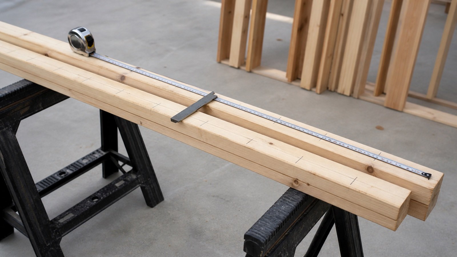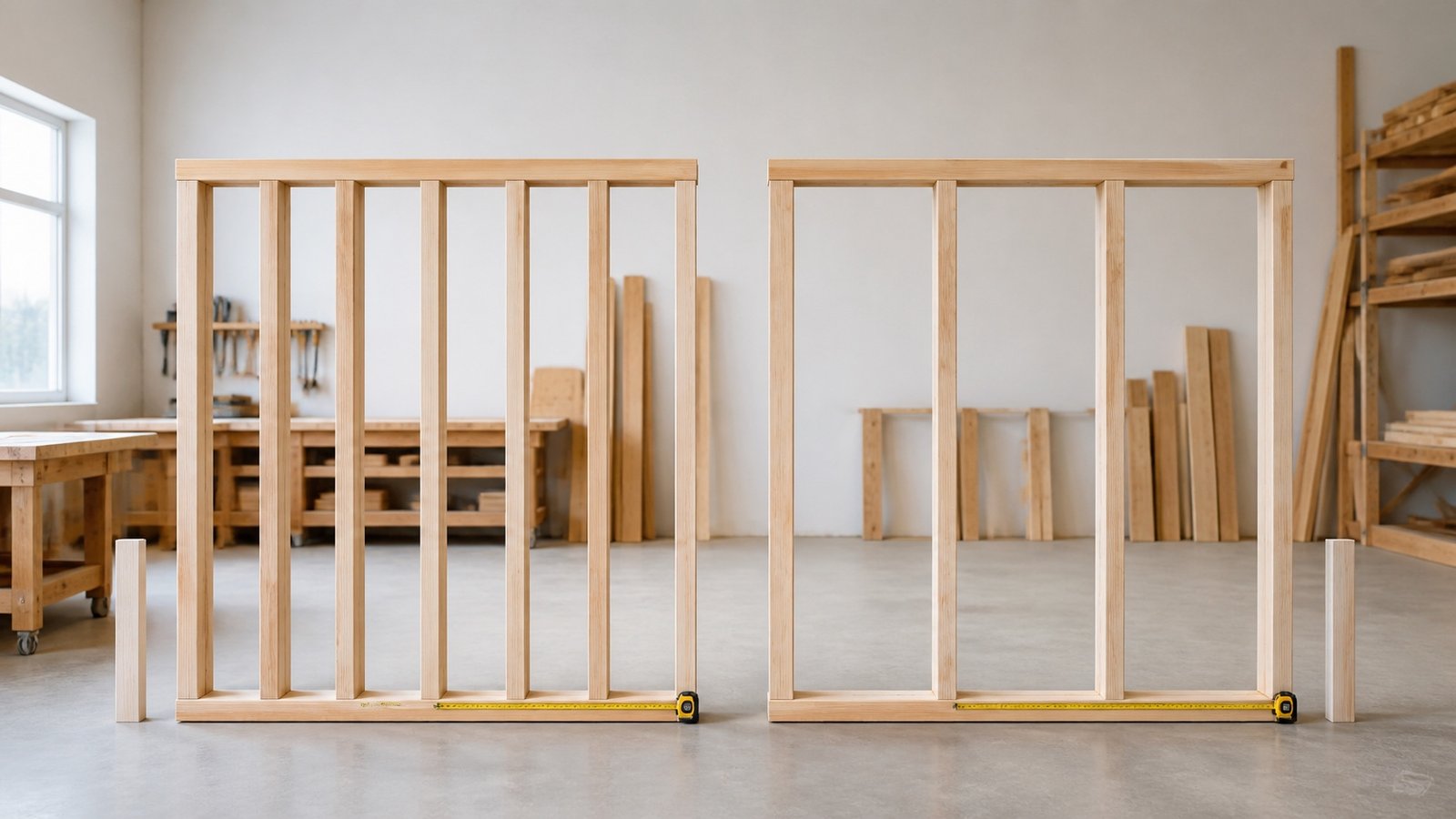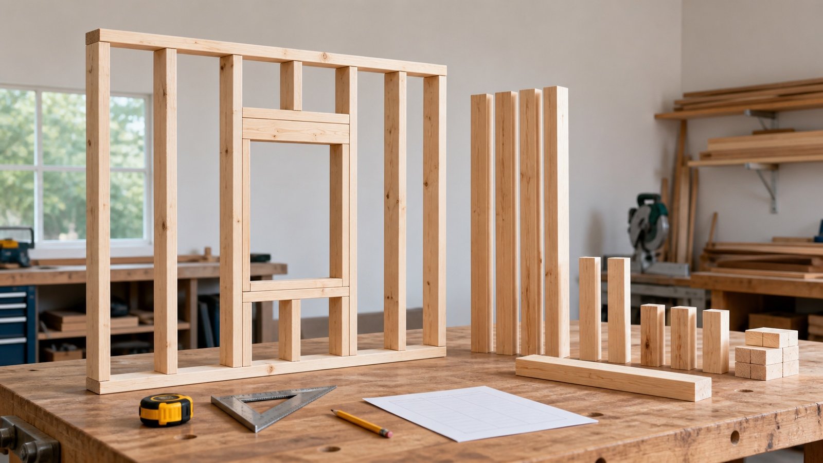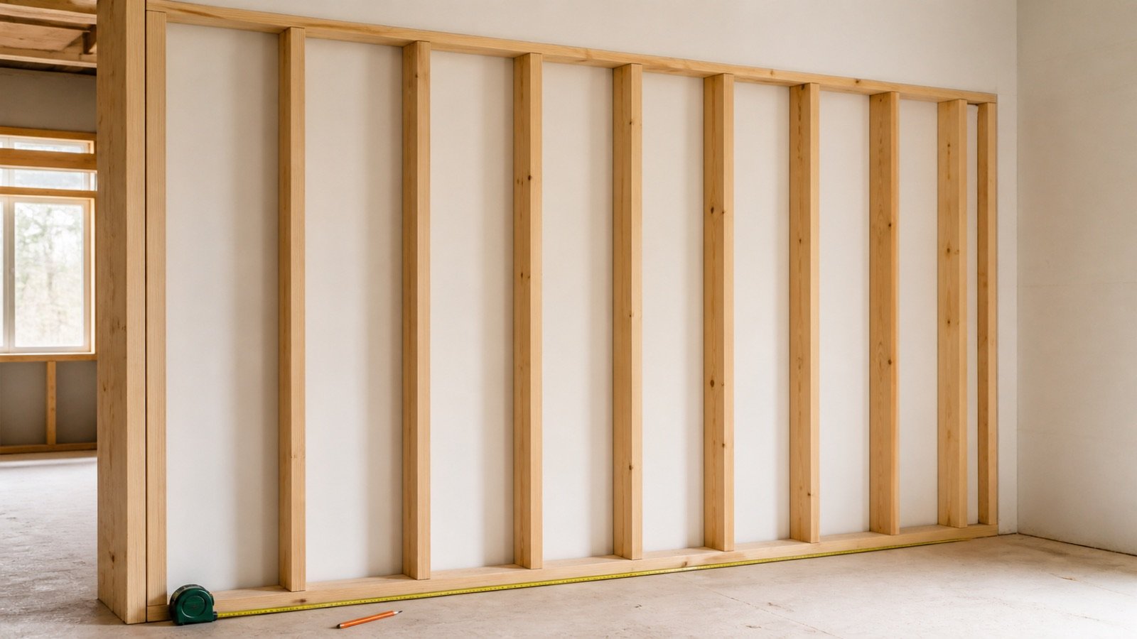
A wall-stud count starts with the length of each straight run and the approved on-centre spacing. Combining several wall lengths before rounding can lose the starting or closing stud that each run needs.
This calculator counts field positions for identical straight runs. It then adds a checked extra-stud total for details that the spacing grid cannot define.
How many wall studs do you need?
Count the starting stud, every full on-centre position and a closing stud at the wall end when the final point falls between spacing marks. Calculate separate runs independently, then add studs required by the approved corner, intersection, opening and backing details.
Enter spacing from the current drawings, specification, accepted design or applicable requirements. The calculator does not choose 12 in, 16 in, 24 in, 300 mm, 400 mm, 450 mm or 600 mm spacing for the project.
Use the wall-stud spacing guide to compare 16 in and 24 in structural, covering, assembly and attachment checks. The wall-stud layout guide explains origins, center positions, member-width edge marks, paired-plate transfer and closing-bay checks. The wall-stud takeoff worksheet reconciles openings, corners, backing and short pieces with the plain field count.
What does the Wall Stud Calculator calculate?
The calculator returns field studs per straight run, field studs across identical runs, full spacing intervals, the closing-stud condition, final-bay width, approved extras, allowance pieces, planning studs, stock applied and studs to purchase.
| Output | Meaning | Check before ordering |
|---|---|---|
| Field studs per run | Starting position, full spacing positions and the run-end position | Accepted run limits and start line |
| Full spacing intervals | Complete entered spacing distances inside one run | Approved spacing and layout direction |
| Closing-stud condition | Whether the wall end lands on a spacing mark or needs another end position | End detail and adjoining construction |
| Final bay | Distance from the last full spacing mark to the closing stud, or one full spacing when the end is on-grid | Field layout and sheet-edge support |
| Approved extra studs | User-entered pieces outside the plain field grid | Corner, tee, opening, backing and engineering details |
| Planning studs | Base count plus entered whole-piece allowance | Allowance reason and acceptance |
| Studs to purchase | Planning studs less usable matching stock | Product identity, grade, length and condition |
What formulas does the calculator use?
The calculator converts the run and spacing to one internal layout unit. Imperial mode converts feet to inches. Metric mode converts metres to millimetres.
Full intervals = floor(run length in layout units ÷ approved spacing)
Grid remainder = run length in layout units − full intervals × spacing
Field studs per run = full intervals + starting stud + off-grid closing stud
Field studs = field studs per run × identical run count
Base studs = field studs + approved extra studs
Allowance studs = ceiling(base studs × allowance ÷ 100)
Planning studs = base studs + allowance studs
Studs to purchase = maximum(0, planning studs − usable matching stock)
An end that lands exactly on the spacing grid already has a stud at that position. An off-grid end receives one closing stud. Small floating-point tolerances prevent an exact converted position from being counted twice.
Worked example: 2 separate 10 ft wall runs
Two identical straight wall runs each measure 10 ft. The accepted layout uses 16 in on-centre spacing. The checked framing details add 8 studs across the 2 runs. The estimator records a 10% full-piece allowance and 3 usable matching studs in stock.
- Convert one run: 10 ft × 12 = 120 in.
- Full intervals: floor(120 ÷ 16) = 7.
- The final grid mark is at 112 in, leaving an 8 in final bay.
- Field studs per run: 7 full intervals + 1 starting stud + 1 closing stud = 9.
- Field studs across 2 runs: 9 × 2 = 18.
- Base count: 18 field studs + 8 approved extras = 26.
- Allowance: ceiling(26 × 10%) = 3 studs.
- Planning count: 26 + 3 = 29 studs.
- Purchase count: 29 − 3 usable stock studs = 26 studs.
The 8 extra studs came from the checked framing details. The calculator does not infer their locations or roles from the number of corners and openings.
Worked example: a 24 ft run on an exact grid
A 24 ft straight run is 288 in long. At an entered 16 in spacing, it contains 18 full intervals and 19 field positions from 0 through 288 in.
The closing stud falls on the spacing grid. Adding another end stud would count the 288 in position twice. The final bay is one full 16 in interval.
Why are separate wall runs counted independently?
Each run has its own start and end conditions. Pooling 2 separate 10 ft runs into one 20 ft length produces a continuous spacing grid that does not exist across the break.
At 16 in spacing, one 10 ft run has 9 field studs. Two such runs have 18. A single continuous 20 ft run has 16 field studs because its grid crosses the point where the separate walls would end and restart.
Use the identical-run field only when lengths, spacing and end rules match. Run another calculation for each different length or layout origin.
How should the spacing input be selected?
Copy the spacing from the accepted project source. Stud size, material, grade, wall height, bearing role, supported loads, wind, bracing, sheathing, gypsum-panel application and local code can change the permitted value.
The 2024 IRC Table R602.3(5) gives different maximum wood-stud spacings across listed stud sizes, heights and supported-load conditions. Chapter 7 also connects gypsum-panel thickness, application and orientation with maximum framing-member spacing. Those tables are scoped model-code examples. The edition adopted for the project, local amendments, drawings and specifications control the work.
Enter the accepted value without rounding it to a familiar spacing. Use a separate calculation when spacing changes within the wall.
Which studs belong in the approved-extra field?
Enter a checked total for full pieces that sit outside the plain start-to-end field grid. Keep a small ledger that names the detail and its source.
| Detail | What to record | Why the calculator asks for a checked total |
|---|---|---|
| Corner | Corner type, backing method and extra full studs | Open corners, conventional multi-stud corners and approved clips use different quantities |
| Partition intersection | Tee location, backing method and extra full studs | Attachment can use multiple studs, ladder backing or another accepted detail |
| Door or window | Opening ID, king studs, jack or trimmer studs, cripples and header reference | Counts depend on opening width, loads, header design and framing system |
| Panel or fixture backing | Backing location, member type and length | Blocking and short pieces may not equal full-height stud stock |
| Control, movement or rated detail | Detail number and required members | Tested or specified assemblies must stay intact |
The American Wood Council notes that studs can occur in multiples at corners and partition intersections and that nailing strips or metal clips can support interior finishes. This supports recording the selected detail. It does not supply one universal extra count.
How should openings be handled?
Mark every field position that crosses the rough opening, then apply the accepted opening detail. Record removed field pieces and required full-height or cut members separately before entering the net full-stud extra count.
The 2024 IRC contains condition-specific header, jack-stud and king-stud provisions. Header span, supported loads, stud spacing and construction system can change those counts. The calculator does not size a header or convert every cripple and sill piece into full-height stud stock.
A full material takeoff should keep full-height studs, trimmers, cripples, sill pieces, headers and blocking on separate rows when their stock lengths or products differ.
How should imperial and metric layouts be compared?
Imperial mode uses feet for wall length and inches for spacing. Metric mode uses metres and millimetres. NIST's current Handbook 44 identifies Appendix C as the unit-conversion reference; 1 international foot equals exactly 0.3048 m and 1 in equals exactly 25.4 mm.
Converted dimensions can describe the same geometry. Product labels and prescribed layout modules may name different nominal systems, so verify the source value rather than replacing 16 in with a rounded 400 mm or 24 in with a rounded 600 mm.
How should allowance and existing stock be recorded?
The allowance adds whole studs after field and approved-extra counts are combined. Set it to 0% until the project record supports extra pieces for selection, handling damage, planned changes or retained spares.
Inspect stock before deducting it. For sawn lumber, the American Wood Council explains that a grade mark identifies species, grade, grading agency and mill number. Match the required member size, length, grade, species or approved product, treatment and condition.
- Exclude twisted, bowed, split, decayed, wet, contaminated or unidentified stock when it fails the project acceptance rules.
- Keep full-height stock separate from short offcuts.
- Cap the deduction at the planning need.
- Record supplier bundle or selling increments after the calculator result when they apply.
Which conditions need another calculation?
| Change | New record |
|---|---|
| Wall-run length or layout start | Field spacing calculation |
| On-centre spacing | Approved spacing source and field count |
| Wood, cold-formed steel or another framing system | Product, member and connection schedule |
| Stud size, height, grade or species | Design and purchase row |
| Bearing and nonbearing walls | Structural scope and approved details |
| Different openings, corners or intersections | Extra-member ledger |
| Single and multi-layer panel assemblies | Panel-support and fastening requirements |
| Rated, acoustic, exterior or braced walls | Complete approved assembly |
Which estimating mistakes change the stud count?
- Dividing the combined length of separate walls by spacing.
- Adding a closing stud twice when the run ends on the spacing grid.
- Omitting the closing stud when the run ends between grid marks.
- Choosing a familiar spacing without checking the project source.
- Using a fixed number of extra studs for every corner or opening.
- Subtracting field studs at openings without applying the complete approved detail.
- Counting short cripples or blocking as full-height pieces without a stock cut check.
- Mixing wood and steel framing in one row.
- Applying allowance before the approved-extra count is complete.
- Deducting mismatched or rejected stock.
What should the wall-stud takeoff record contain?
- Project, level, room, wall ID and drawing revision.
- Run start, run end, measured length and layout direction.
- Approved on-centre spacing and source reference.
- Stud material, size, length, grade, species or product designation.
- Field positions per run, closing-stud condition and final bay.
- Opening, corner, intersection and backing detail references.
- Full studs, cut members, allowance, stock deduction and purchase count.
- Prepared by, checked by, date and unresolved design questions.
Carry the accepted result into the drywall material takeoff worksheet. Use the Drywall Calculator for panel-area and rectangular-grid checks.
Safety, design and code limits
The calculator estimates vertical field positions and user-approved extra full studs. It does not design a wall, size a stud or header, check loads, verify bracing, set fastening, approve notches or holes, or establish fire, sound, moisture, exterior and movement-joint performance.
Follow current drawings, specifications, product instructions, temporary-bracing procedures and the locally adopted code. Structural walls, tall walls, large openings, unusual loads and altered existing construction can require a qualified designer or engineer.
Return to the Drywall planning hub for panel, tape, compound, screw and corner-bead tools. Review the calculation methodology or report a formula or source issue through the corrections route.
Sources and source scope
- 2024 IRC Chapter 6, Wall Construction: model-code examples for wood-stud size, height, spacing and condition-specific opening framing.
- 2024 IRC Chapter 7, Wall Covering: model-code examples connecting gypsum-panel conditions with framing-member spacing.
- American Wood Council, Lumber Studs: member role, grade-mark traceability and corner or intersection backing options.
- NIST Handbook 44, current 2026 edition: official Appendix C unit-conversion reference.
Source scope: the code pages support only their stated edition and conditions. Local adoption and amendments control project use. AWC supplies general wood-framing context. NIST supports unit relationships. None of these sources approves the entered spacing, extra-stud total, allowance, stock condition or finished design.
Review note: Saleem Sial owns the research and editorial record. Source checks, independent formula fixtures, interface tests, build validation, link crawl, schema review and rendered QA form the internal publication gate. Waseem Sial, External Reviewer and Engineer, is listed for ongoing external review; no completed review date is claimed.