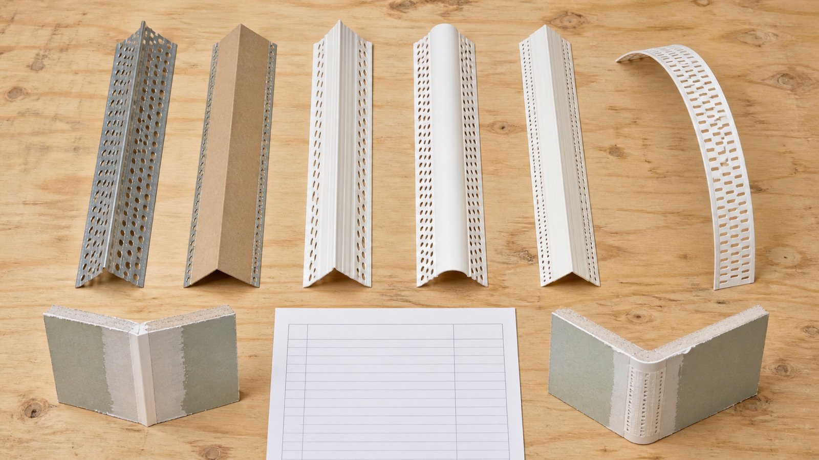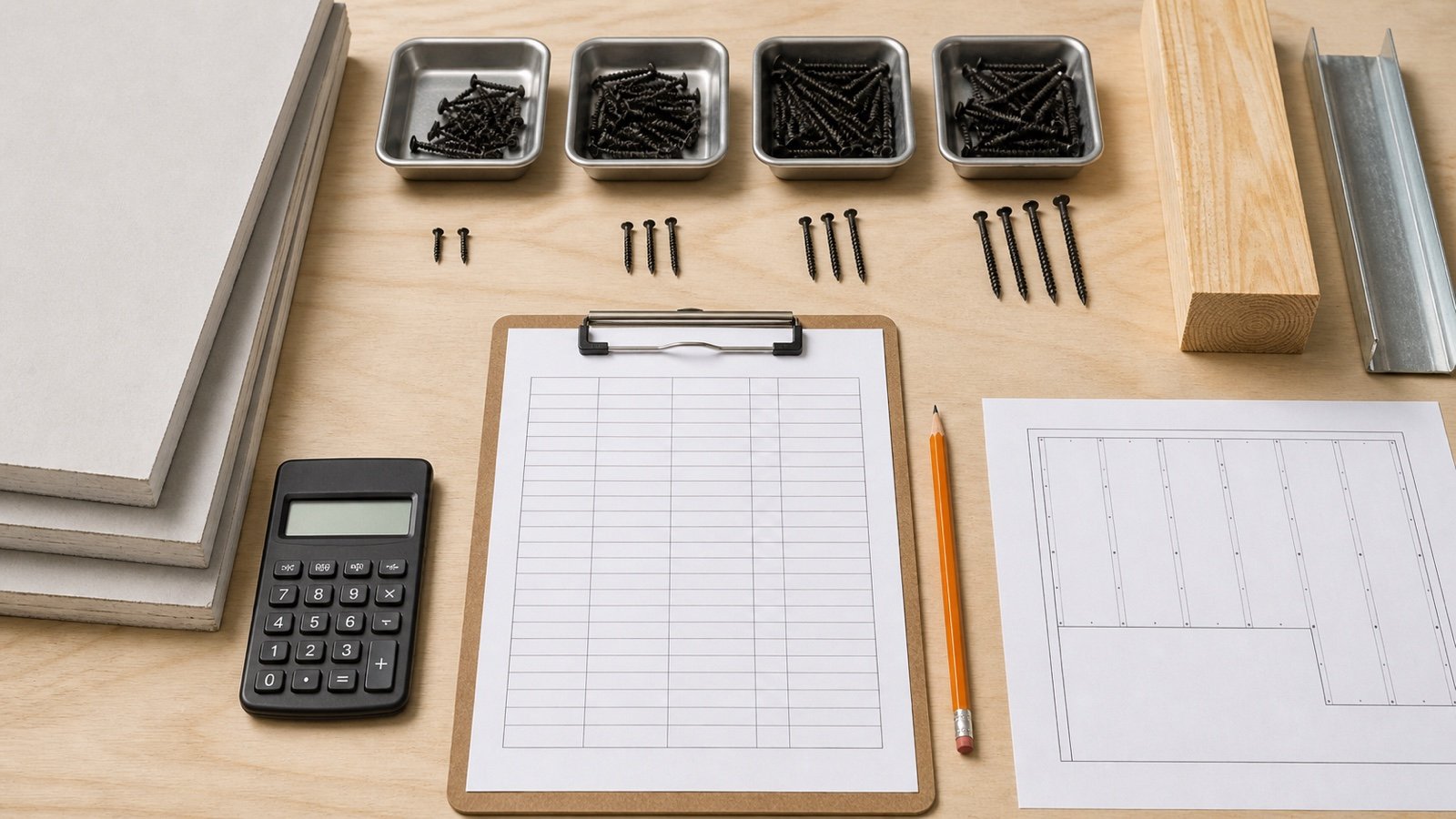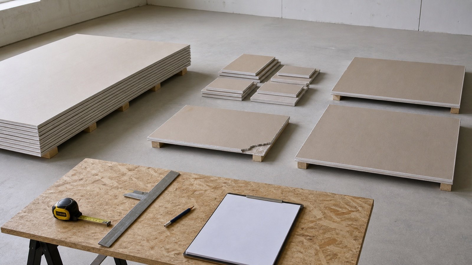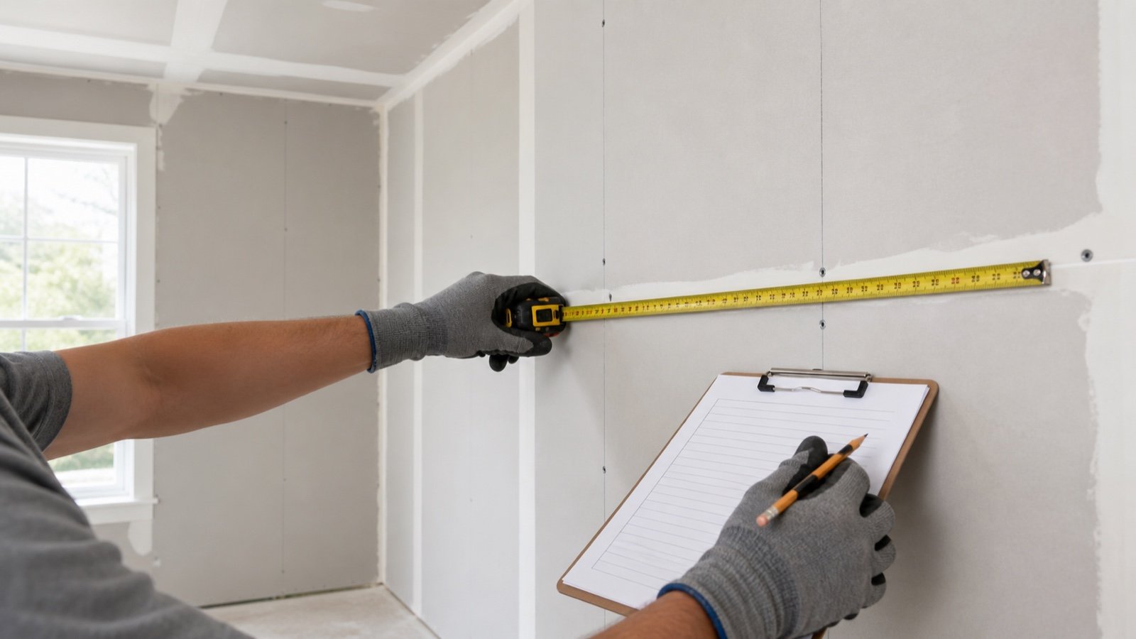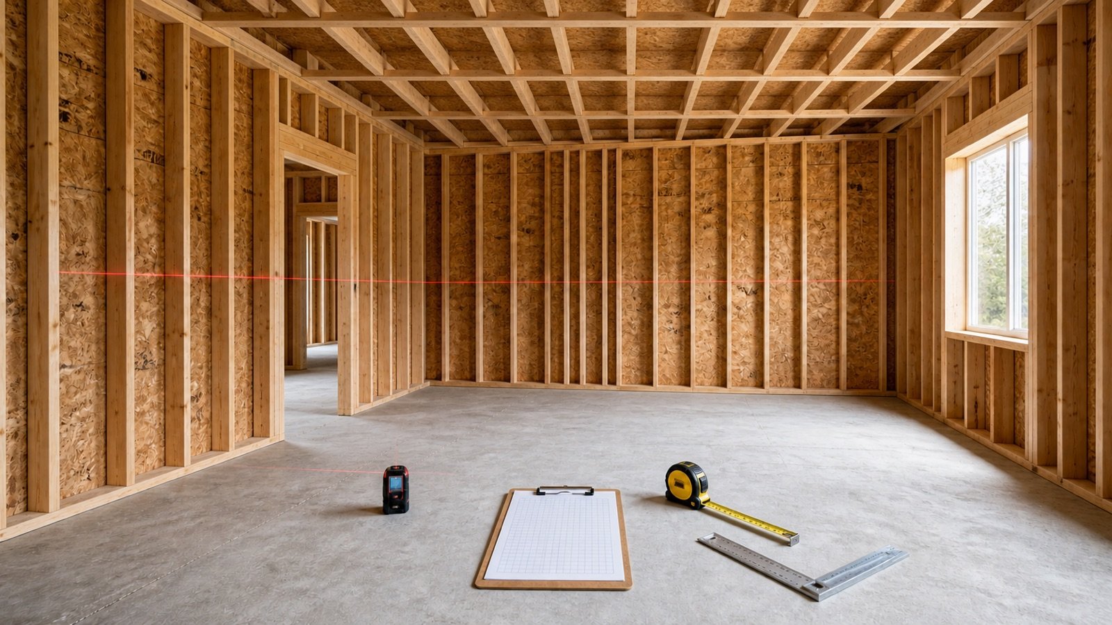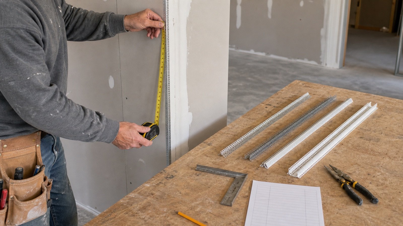
A corner-bead takeoff starts with the edges that the selected finish system will cover. Count and measure each physical run, record its endpoints and product, then group only runs that share the same finished cut length and stock item.
This run ledger prevents a common ordering error: dividing pooled linear feet by stock length even when separate vertical corners cannot share short offcuts.
How do you measure drywall corner bead for a takeoff?
Mark every outside corner, return, soffit edge, opening edge and column edge that receives the selected bead or trim. Measure each run between defined endpoints, apply the current product's cut instruction, and enter the finished cut length on its own ledger row.
- Confirm the drawing, finish detail and selected corner product.
- Assign a location and run ID to each treated edge.
- Measure between physical endpoints along the bead nose path.
- Record vertical, horizontal, sloped or curved orientation.
- Apply the named product's end clearance or transition detail.
- Dry fit field-measured cuts where the manufacturer requires it.
- Group only matching runs and send them to the calculator.
Use the Drywall Corner Bead Calculator after the ledger identifies the run count, finished cut length, stock length and package quantity.
Which edges belong in the corner-bead takeoff?
Include each edge that the current drawings, specifications or selected product instructions assign to corner bead or trim. A floor-plan point count cannot tell whether an edge is exposed, full height or treated with another detail.
| Edge or condition | Takeoff action | Record needed |
|---|---|---|
| Vertical outside wall corner | Measure the treated vertical run | Floor, ceiling and end-clearance condition |
| Soffit or bulkhead edge | Measure each horizontal and vertical segment | Segment endpoints and intersections |
| Uncased opening return | Measure every edge receiving the selected trim | Jamb, head, sill and corner-transition detail |
| Column or box-out | Measure each physical edge by face and level | Profile, angle and repeated height |
| Bullnose or chamfer corner | Keep under its named profile | Radius or profile plus caps and transitions |
| Curved opening | Measure the accepted curve path | Flexible product and arc measurement |
| Inside taped angle | Keep in the joint-tape ledger when that system uses tape | Selected inside-angle treatment |
| Control, movement or reveal joint | Use the project accessory schedule | Named detail and product |
The drywall joint measurement guide handles ordinary taped joints and inside angles. Keep those lengths out of the outside-corner bead subtotal unless the chosen system states another treatment.
What should a corner-bead measurement ledger contain?
The ledger should let another person locate the run and reproduce its finished cut length. A note such as “120 linear feet of bead” cannot show missed returns, mixed profiles or an unsupported joint.
| Field | Record | Check |
|---|---|---|
| Location | Level, room, elevation, opening, soffit or column | Matches the current drawing or field sketch |
| Run ID | Unique mark for one continuous piece | Appears once in the ledger |
| Run class | Vertical, horizontal, sloped, curved or transition | Uses the correct measurement method |
| Endpoints | Finished floor, ceiling, intersecting bead, return or termination | Both ends are defined |
| Selected product | Manufacturer, name, stock number, profile, angle and material | Matches the approved detail |
| Measured geometry | Field or drawing length before product adjustment | Unit and source are shown |
| Cut instruction | End clearance, cap, miter, transition or joint requirement | Current source is attached |
| Finished cut length | Length used for cutting and quantity calculation | Arithmetic is visible |
| Repeat count | Whole count of identical runs | Geometry and end conditions match |
| Revision | Drawing or field-check date and status | Superseded rows are removed |
How should field measurements be taken?
Measure the actual corner after the board and relevant floor or ceiling reference are known. Hold the tape along the path the bead nose will occupy and record the endpoints before subtracting a product-specific clearance.
- Confirm that the board corner is ready for the selected bead to fit.
- Mark the bottom and top or the 2 horizontal endpoints.
- Measure the full geometric distance between those marks.
- Check a second point when the floor, ceiling, opening or soffit is out of level.
- Write the measured length before making a cut.
- Apply the selected product's documented end condition.
- Cut and dry fit according to the manufacturer's current method.
- Return changed dimensions to the takeoff ledger.
USG J371 tells users of its named paper-faced metal method to measure the corner and cut vertical trim 1/2 in (12.7 mm) shorter than wall height. The CGC guide gives the same 13 mm instruction for its named paper-faced bead. Trim-Tex describes measuring, cutting and dry fitting, with a 1/2 in base gap in the condition where flooring has not been installed.
Those documents support their products and stated conditions. Copy the instruction for the bead on the job. A 1/2 in deduction should not become a site-wide default for unrelated metal, vinyl, flexible, bullnose, reveal or proprietary trims.
How should corner bead be measured from plans?
Use elevations, reflected ceiling plans, wall types, details and finish schedules together. A plan view can identify a corner location while an elevation supplies height, interruptions and top or bottom conditions.
- Trace every wall end, outside turn, chase, column and box-out on the plan.
- Use elevations to split full-height and partial-height runs.
- Add soffit edges and opening returns from their details.
- Check finish transitions, ceiling steps and base conditions.
- Assign the specified bead or trim profile before totaling.
- Record unresolved edges as pending instead of guessing a length.
Do not multiply every plan-view outside point by one ceiling height when bulkheads, half walls, sloped ceilings or openings change the run. Keep a count check beside the measured ledger so a missed corner can be found without replacing the measured lengths.
What is the difference between measured length and cut length?
Measured length describes the physical distance between reference points. Cut length applies the accepted end clearances, caps, miters or transitions to that measured geometry.
Finished cut length = measured geometric length + approved end additions − approved end clearances
Record each adjustment by end. “Minus 1/2 in” gives no clue whether the clearance belongs at the floor, ceiling or both. End A and End B fields keep the arithmetic tied to the product detail.
A field checker needs the full geometric length and the product adjustment. Storing only the final cut size hides the reason for the deduction and makes a product change harder to reconcile.
When can corner-bead runs be grouped as identical?
Group runs when the complete product identity, cut length and both end conditions match. Similar wall heights alone do not make 2 runs identical.
Use one repeated row only when all of these fields agree:
- manufacturer, product and stock number;
- profile, angle or radius and material;
- attachment and finish system;
- finished cut length;
- top, bottom and intersection detail;
- straight, sloped or curved condition;
- current drawing or field revision.
Example: 6 vertical corners measure 8 ft. The declared USG paper-faced method shortens each cut by 1/2 in, giving 6 identical cuts at 7 ft 11.5 in. Under declared 10 ft stock, each piece supplies one complete vertical run, so the base need is 6 pieces.
The total cut length is 47 ft 9 in. Dividing 47.75 ft by 10 ft and rounding up returns 5 pieces. Five pieces cannot supply 6 complete 7 ft 11.5 in runs. The calculator's identical-run mode checks complete cuts per stock piece before rounding the piece count.
How do mixed run lengths change the stock count?
Mixed runs need a cutting list because pooled length cannot show which cuts share one stock piece. Keep every physical offcut separate and assign it only when its length, product and condition suit a remaining run.
| Run | Finished cut | Assigned stock piece |
|---|---|---|
| Vertical V1 | 7 ft 11.5 in | Piece 1 |
| Vertical V2 | 7 ft 11.5 in | Piece 2 |
| Soffit S1 | 6 ft 2 in | Piece 3 |
| Header H1 | 3 ft 4 in | Piece 3 |
| Return R1 | 2 ft 9 in | Piece 4 |
The cuts total 28 ft 2 in. A linear calculation rounds that total to 3 pieces of 10 ft stock. The 2 vertical runs each consume their own piece, and the 6 ft 2 in soffit can share a third piece with the 3 ft 4 in header. The 2 ft 9 in return does not fit any remaining offcut, so the checked list needs 4 pieces.
Four pieces provide 40 ft of stock and leave 11 ft 10 in unallocated across separate pieces. That aggregate remainder is not one continuous 11 ft 10 in offcut. Record each remnant by physical piece before crediting it elsewhere.
How should openings, soffits and columns be measured?
Split complex work at every corner, transition and product change. One opening can contain 2 jamb runs, a head run, a sill condition and several three-way intersections.
| Condition | Measurement check | Separate item |
|---|---|---|
| Door or window return | Measure jambs, head and sill treatment by edge | Caps, miters and casing transitions |
| Soffit or bulkhead | Measure each horizontal and vertical line between intersections | Inside angles and control joints |
| Four-sided column | Count and measure each treated vertical edge | Base and ceiling terminations |
| Half wall | Measure vertical ends and any horizontal cap edges | Three-way corner components |
| Sloped ceiling | Measure the actual sloped run | Angle-specific or flexible profile |
| Curved opening | Measure the arc path required by the product | Flexible bead and transition pieces |
A straight chord across a curved opening is shorter than the arc. Use the measurement method in the selected flexible product's instructions and keep curved stock or rolls out of the straight-piece calculation.
How should feet, inches and metres be recorded?
Use one unit system within each subtotal. NIST Handbook 44 Appendix C states that 12 in equals 1 ft and the international foot equals 0.3048 m exactly.
Convert each source measurement before adding rows. For example, 7 ft 11.5 in equals 95.5 in, 7.958333 ft or 2.4257 m when reported to 4 decimal places. Keep more precision in the calculation record and round the field cutting mark to the method and tool appropriate for the selected product.
A locally sold 3 m bead is a 3 m product. It is not the same stock length as a 10 ft bead, which equals 3.048 m. Use the current supplier item in the piece calculation.
How should a revised corner-bead takeoff be checked?
Reconcile added, removed and changed runs against the previous accepted ledger. Replace superseded rows instead of stacking a new total on top of the old one.
Revised measured total = accepted total + added runs − removed runs + length changes
A zero net length can still change the stock count. Replacing one 6 ft run with 2 separate 3 ft runs changes the cut layout even though the pooled length remains 6 ft. Keep the run IDs and cutting list current.
How does the ledger become a material order?
Send one product group at a time to the Drywall Corner Bead Calculator. Use identical-run mode for repeated complete cuts. Use direct mode after a checked cutting list approves the base stock-piece count for mixed lengths.
- Confirm the finished cut lengths and product group.
- Copy the current stock-piece length.
- Calculate the base pieces.
- Add a documented full-piece allowance when the project record supports it.
- Deduct matching usable stock.
- Enter the current pieces per package or 1 for individual sales.
- Record the whole packages and package remainder.
Trim-Tex's current Corner Bead and Archway page lists several stock lengths and a package quantity for that named family. Other profiles and suppliers can use different stock and selling increments. Confirm the exact item and local availability before the order.
Carry the accepted trim rows into the drywall material takeoff worksheet with panels, tape, compound and fasteners. Keep each product subtotal traceable through purchase and field issue.
Which measurement errors change the bead order?
- Counting every plan corner without checking its finish detail.
- Using one average height for full walls, half walls and soffits.
- Combining outside bead with ordinary inside-angle tape.
- Applying a 1/2 in gap to every product and end condition.
- Measuring an opening perimeter as one continuous cut.
- Using a curve's straight chord as its bead length.
- Grouping different profiles or stock numbers.
- Dividing total length by stock length without checking complete cuts.
- Joining 2 offcuts without product and project approval.
- Crediting aggregate remainder as one physical offcut.
- Mixing feet and metres in one subtotal.
- Adding revised rows without removing superseded runs.
Safety, product and project limits
Measure from a safe working position and use access equipment suited to the task. USG J371 describes cutting metal bead flanges with tin snips and tells users to wear gloves to protect their hands. Follow the selected product's cutting method and current site rules for sharp edges, tools, ladders, adhesives, dust and personal protective equipment.
This article prepares a quantity record. Project drawings, specifications, tested assemblies, selected manufacturer instructions, local requirements and qualified project professionals control product selection, corner geometry, attachment, movement details, fire or sound construction and installation acceptance.
Return to the Drywall planning hub for the published sheet, tape, compound, screw and trim workflow. The calculation methodology explains unit and rounding checks. Send a source or arithmetic issue through the corrections route.
Sources and source scope
- USG Sheetrock Brand Installation and Finishing Guide J371 supports the named paper-faced metal measurement and 1/2 in vertical cut instruction, the tin-snip method and glove note.
- CGC Sheetrock Installation and Finish Guide supports the stated Canadian paper-faced bead measurement and 13 mm cut instruction.
- Trim-Tex corner-bead installation article supports its measure, cut and dry-fit sequence and its unfinished-floor base-gap condition.
- Trim-Tex Corner Bead and Archway product page supports the named product family's current stock-length and package examples.
- NIST Handbook 44, 2026 Appendix C supports the exact inch, foot and metre relationships.
Source scope: Manufacturer sources cover their named products, methods and conditions. NIST supports unit conversion. They do not approve the example cutting lists, a universal clearance, a project allowance, a local package or another manufacturer's system.
Review note: Saleem Sial owns the research and editorial record. Source checks, independent arithmetic, editorial review, internal-link review, build validation, crawl, schema review and rendered QA form the internal publication gate. Waseem Sial, External Reviewer and Engineer, is listed for ongoing external review; no completed review date is claimed.