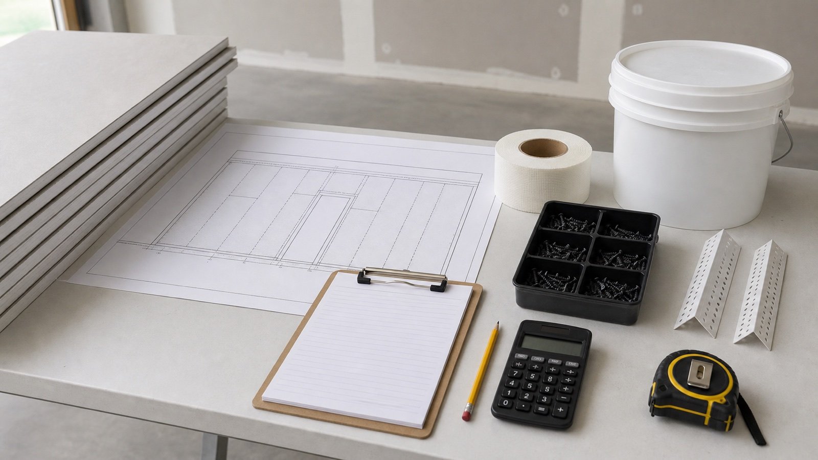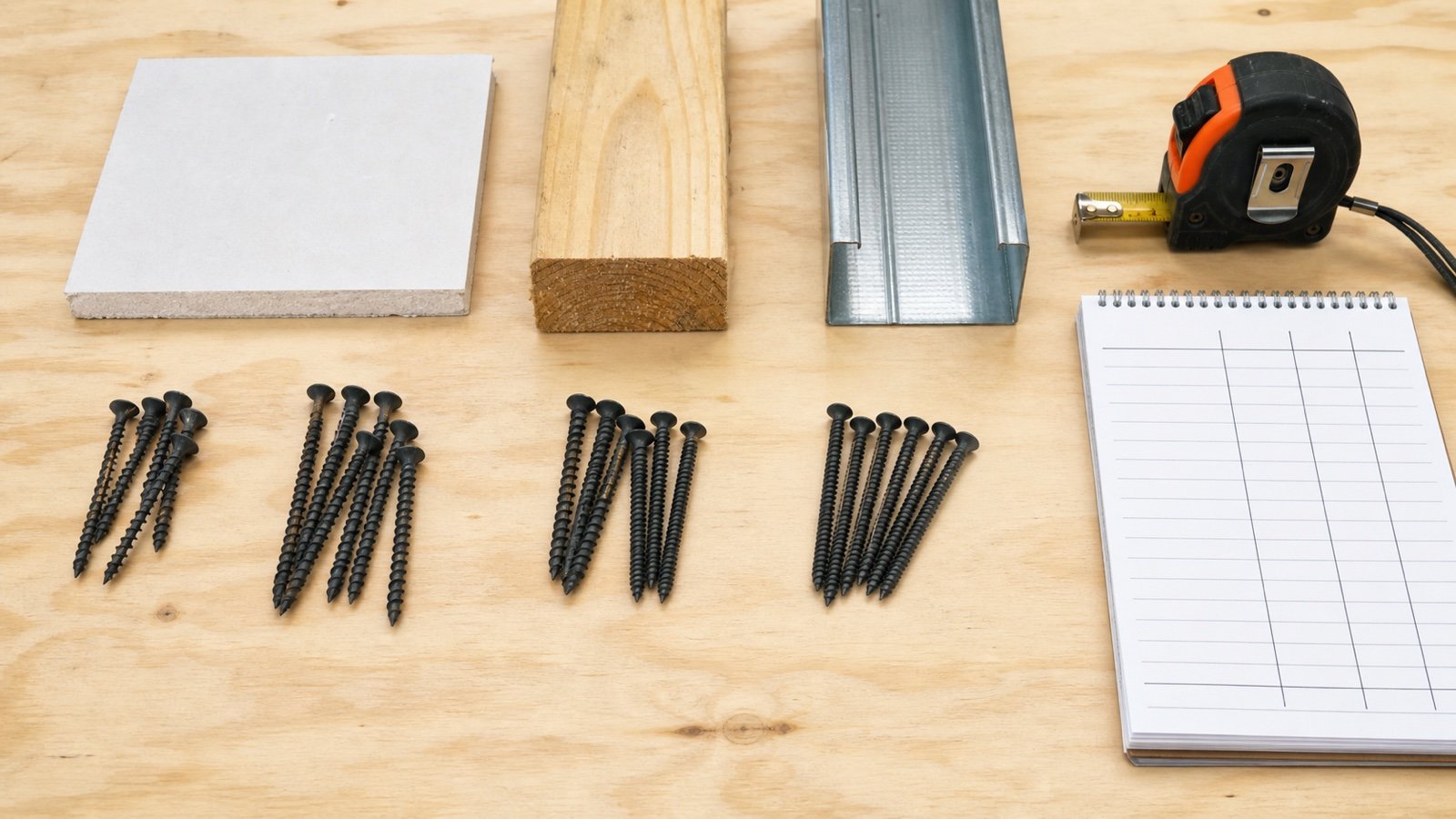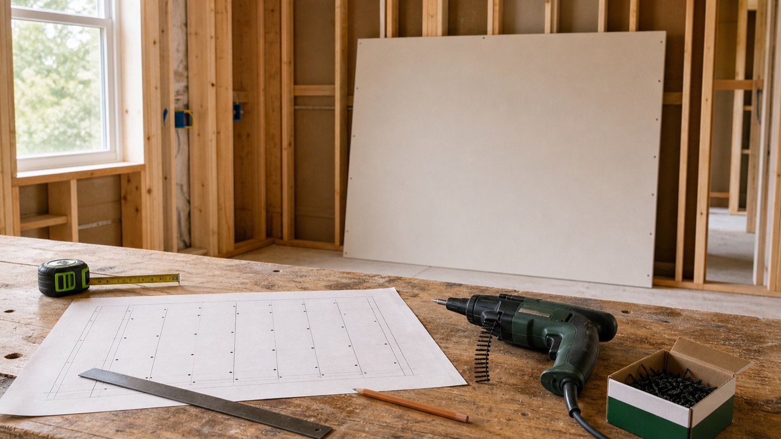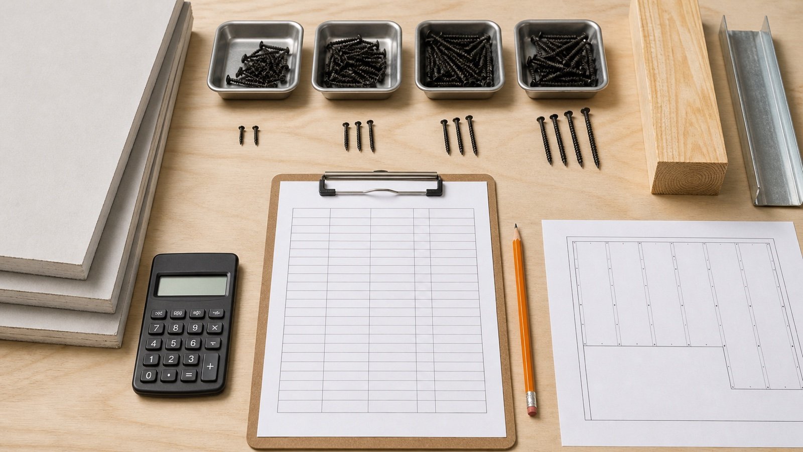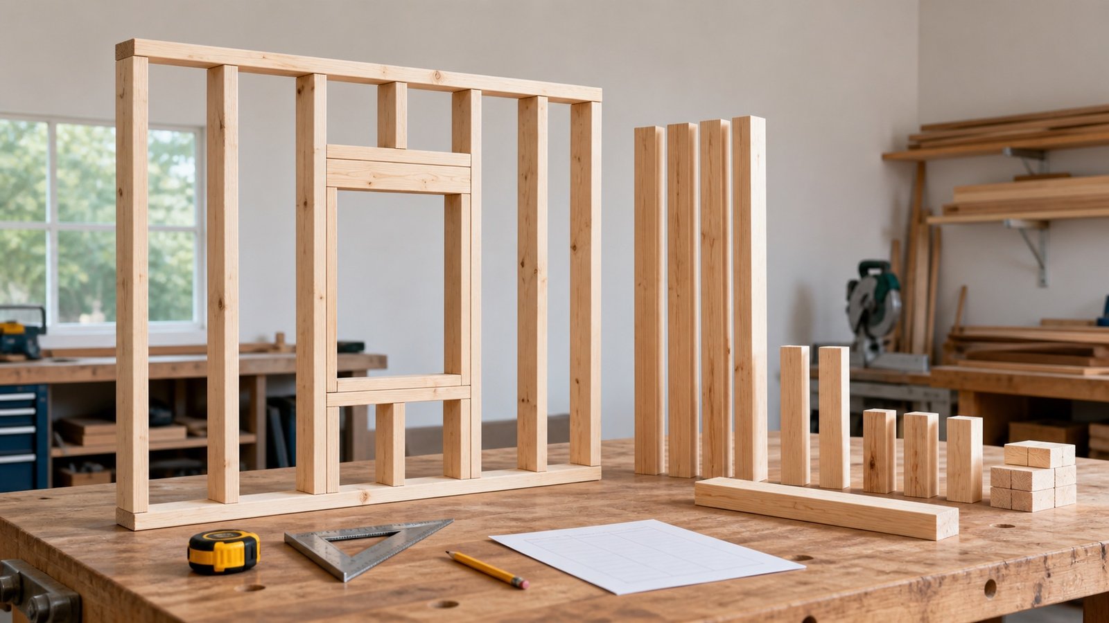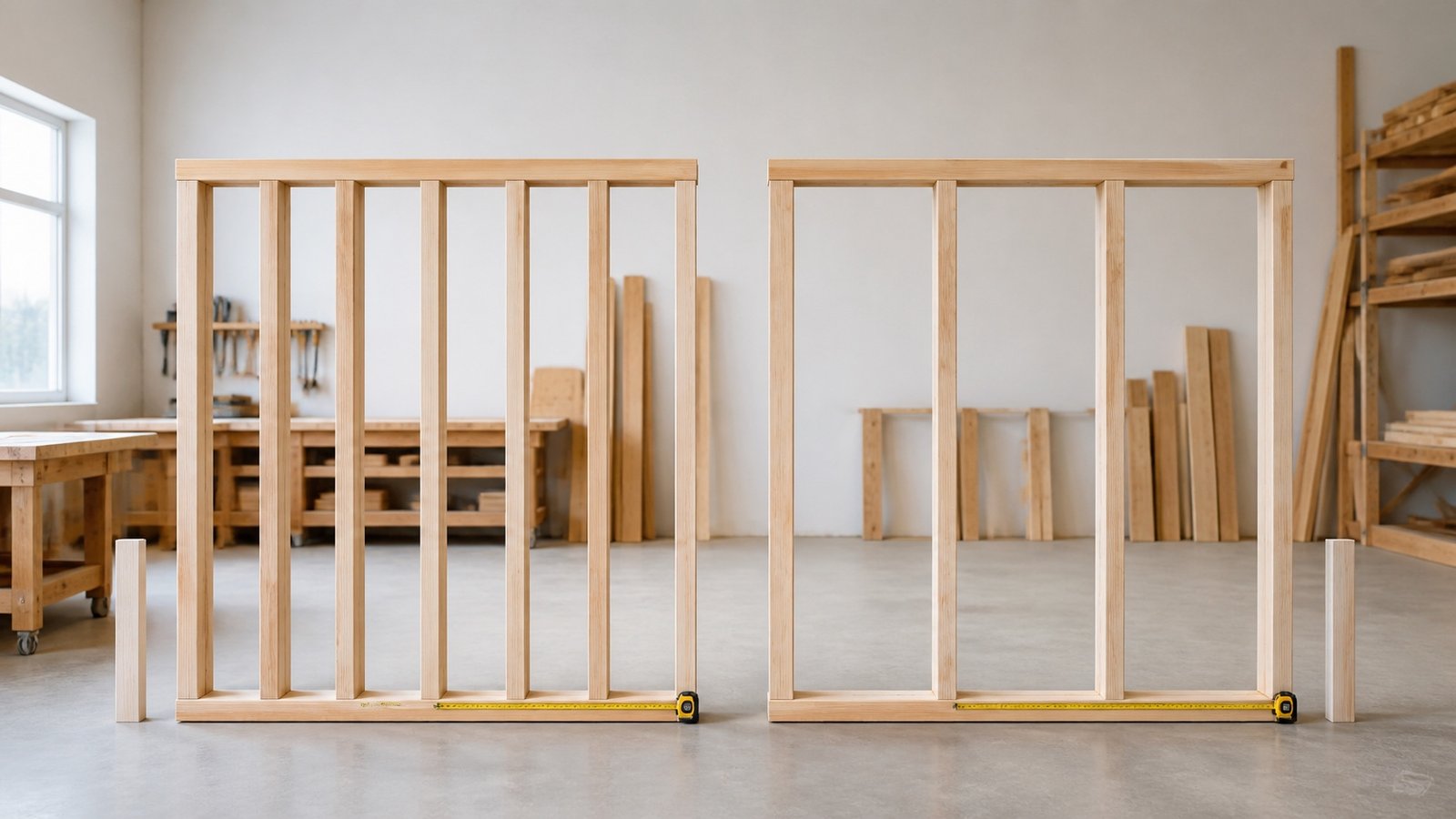
Choosing wall-stud spacing affects more than the number of studs on an order. The spacing must work with the wall's loads, member size and height, sheathing or gypsum system, openings, attachments and locally accepted design.
Use 16 in and 24 in as values to compare after those checks. Do not select either one from habit or from a material-savings claim alone.
Should wall studs be 16 or 24 inches on center?
Use the spacing shown by the accepted drawings, specifications or design for that wall. A 16 in grid provides more field positions, while 24 in uses fewer field studs. Either choice can be unsuitable when the structural conditions, covering system, tested assembly or attachment plan requires something else.
The 2024 International Residential Code sends wood-stud size, height and spacing decisions to condition-based tables. Gypsum Association guidance also connects maximum framing spacing with panel thickness, orientation, wall or ceiling use, layers and tested-system status. Check both sides of the wall system before entering a spacing in the Wall Stud Calculator.
| Check | Record | Why it can change the spacing |
|---|---|---|
| Structural source | Wall type, stud material and size, height, grade, loads, bracing and design reference | Permitted spacing depends on the listed or engineered conditions |
| Wall covering | Panel product, thickness, orientation, layers, edge support and fastener or adhesive method | The covering may have a smaller maximum support spacing |
| Tested assembly | Fire, sound or other assembly number and complete construction | Changing framing spacing can take the wall outside the tested configuration |
| Attachments | Cabinets, rails, fixtures, cladding and backing details | Wider bays can require a different attachment or backing plan |
| Local acceptance | Adopted code edition, amendments, permits and approved project documents | Model guidance does not establish local approval by itself |
What does on-center spacing measure?
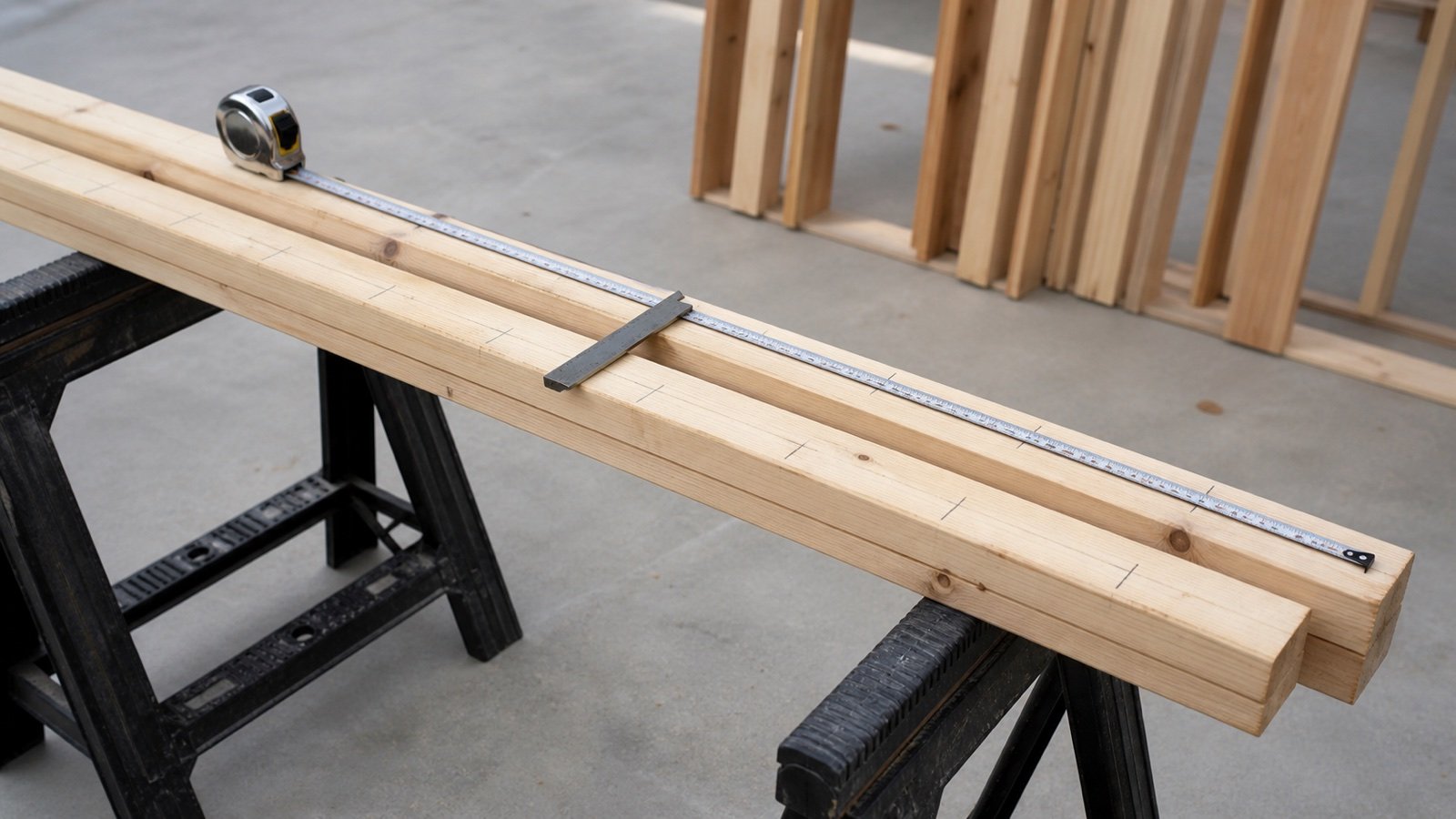
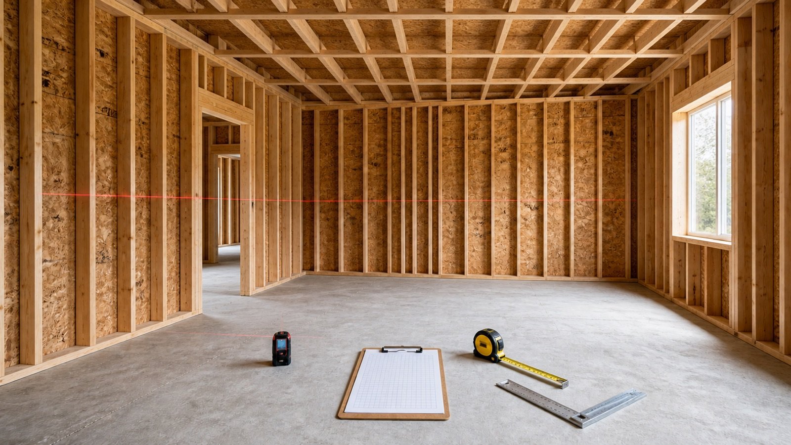
On-center spacing is the distance from the centerline of one repeated framing member to the centerline of the next. It sets a module; it does not describe the clear opening between stud faces.
A 16 in on-center grid has center positions at 0, 16, 32, 48 in and so on from the accepted origin. A 24 in grid uses 0, 24, 48, 72 in and so on. The physical end of an off-grid wall still needs its accepted closing detail.
The wall-stud layout guide explains how to turn accepted center positions into edge lines on paired plates and how to check a shorter closing bay.
Which structural conditions control stud spacing?
Wall role, material, member dimensions, height and supported loads belong in the structural check. Wind, bracing, openings, connections and local amendments can add other limits.
The American Wood Council describes 16 in exterior-wall spacing as normal in conventional wood framing and notes that 24 in spacing can be acceptable for some one-story 2x4 conditions when the covering can bridge the spacing. Its page also gives a more restrictive multi-story example. These examples show why a one-line rule such as “bearing walls use 16 in” cannot approve a project.
- Match the wall ID to the current drawing and revision.
- Record whether the wall is bearing, nonbearing, exterior, braced or part of another named system.
- Confirm stud material, actual size, grade or product designation and unsupported height.
- Check gravity, wind and other loads stated by the design.
- Check openings, headers, connections, notches, holes and temporary bracing separately.
- Use the adopted code edition and local amendments, not an undated online summary.
If the documents conflict or omit the spacing, send the question to the responsible designer, building official or other authorized project decision-maker. A quantity calculator cannot settle a structural design choice.
How can drywall or sheathing limit the spacing?
The covering system needs adequate support under its approved installation method. Panel type, thickness, orientation, number of layers, joint treatment and tested-system status can affect the permitted framing spacing.
The Gypsum Association's spacing preview tells users to consider whether the surface is a wall or ceiling, whether panels run parallel or perpendicular to framing, and whether the work must match a tested system. GA-216 then provides application guidance over appropriately spaced wood or steel framing. Product instructions and the complete project specification can be more specific.
| Item | Question for the project record |
|---|---|
| Panel identity | What product, thickness and edge type is specified? |
| Orientation | Will the panel's long dimension run parallel or perpendicular to the studs? |
| Layers | Is the wall single-layer, multi-layer or part of a tested assembly? |
| Edges and joints | Where do panel edges land, and which edges need framing or another approved support? |
| Attachment | Which fastener, spacing, adhesive and substrate requirements apply? |
| Exposure and finish | Do moisture, exterior exposure, tile, veneer, impact or finish requirements change the support? |
A structural table can permit a wider stud grid while the selected covering or assembly requires closer support. Record the smaller accepted limit instead of checking only the framing member.
When does 24-inch spacing form part of advanced framing?
In advanced framing, 24 in on-center studs work as one part of a coordinated system. The U.S. Department of Energy Building America guide describes 2x6 studs on a two-foot module alongside aligned floor and roof framing, planned openings and reduced redundant framing.
Changing one wall from 16 in to 24 in without checking that coordination can move panel edges, loads and attachments away from their planned supports. A complete review should cover:
- stud size, grade, wall height and approved structural design;
- alignment of studs with floor joists, roof framing or point loads where required;
- window and door dimensions on the selected module;
- corner and partition-intersection details;
- sheathing, gypsum, insulation and cladding compatibility;
- cabinet, handrail, service and fixture backing;
- local restrictions, including wind or hurricane-zone provisions;
- crew layout, procurement and inspection records.
The advanced-framing label does not approve a wider grid by itself. Keep the system detail or drawing reference beside the takeoff.
How many field studs do 16-inch and 24-inch grids use?
For a plain straight run with both physical ends counted, divide the run length by spacing, keep the whole intervals and add the starting position. Add one closing position only when the run ends between grid marks.
Full intervals = floor(run length ÷ approved spacing)
Remainder = run length − full intervals × spacing
Field positions = full intervals + 1 starting position + 1 closing position when remainder is greater than 0
| Straight run | 16 in grid | 24 in grid | Difference |
|---|---|---|---|
| 8 ft / 96 in | 7 positions | 5 positions | 2 |
| 10 ft / 120 in | 9 positions, 8 in closing bay | 6 positions, exact grid | 3 |
| 12 ft / 144 in | 10 positions | 7 positions | 3 |
| 20 ft / 240 in | 16 positions | 11 positions | 5 |
On the plain 12 ft run, the 24 in grid uses 3 fewer field positions than the 10 positions at 16 in, a 30% reduction for that isolated row. On the 20 ft run, the difference is 5 positions, or 31.25% of the 16 in field count.
Those percentages cover the repeated field only. Corners, intersections, openings, headers, trimmers, cripples, backing, plates and cut pieces remain outside the comparison.
Worked example: a 10 ft wall
A 10 ft wall is 120 in long. At 16 in, floor(120 ÷ 16) gives 7 full intervals and an 8 in remainder. Count the origin, 7 grid positions and the off-grid physical end for 9 field positions.
At 24 in, 120 ÷ 24 gives 5 exact intervals. Count the origin and the 5 following positions for 6 field positions. Another closing stud would duplicate the position at 120 in.
Run each separate wall independently. Combining two wall lengths before rounding can remove the start or end positions needed at the break.
Does wider spacing always reduce the project cost?
Fewer field studs can reduce one material row, but the project cost changes only after the complete approved wall systems are priced. Member size, covering, backing, insulation, fasteners, clips, waste, labor and inspection needs can offset the field-stud difference.
| Cost row | 16 in option | 24 in option | Evidence to keep |
|---|---|---|---|
| Field studs | Calculated by run | Calculated by run | Run schedule and approved spacing |
| Stud size and grade | Specified product | Specified product | Design and supplier quote |
| Openings and backing | Detail-based count | Detail-based count | Detail ledger |
| Sheathing and interior panels | Approved system | Approved system | Product and assembly instructions |
| Insulation and services | Matching module and labor | Matching module and labor | Takeoff and installation plan |
| Fasteners, clips and connectors | System quantity | System quantity | Connection schedule |
| Labor and waste | Current project estimate | Current project estimate | Crew method and dated quote |
Use current local supplier and labor quotes when money matters. A national percentage from another project cannot establish the saving on this one.
What changes when fixtures need support?
Cabinets, rails, grab bars, televisions, cladding and equipment need an attachment path that matches their loads and product instructions. Wider stud spacing may change where direct-to-stud attachment is available.
Record fixture locations and loads before closing the wall. Use the approved blocking, panel, fastener, anchor or proprietary support detail. Avoid a universal blocking quantity because backing requirements vary by fixture, wall system and accessibility or safety scope.
For rated, acoustic, braced or movement-sensitive walls, an extra member or fastener can also alter the listed or tested construction. Keep the full assembly reference with the layout decision.
Are 16 inches and 400 mm the same module?
No. The exact conversion is 16 in = 406.4 mm, while 24 in = 609.6 mm. A 400 mm or 600 mm grid is a separate specified module, even when someone uses the pairs as rough comparisons.
NIST supports the exact relationship 1 in = 25.4 mm. Use the project unit throughout one run rather than rounding an approved module.
| Module | Exact converted value | 4.8 m run |
|---|---|---|
| 16 in | 406.4 mm | Requires a run calculation in the original module |
| 400 mm | 15.748 in | 12 intervals, 13 positions |
| 24 in | 609.6 mm | Requires a run calculation in the original module |
| 600 mm | 23.622 in | 8 intervals, 9 positions |
The calculator keeps imperial and metric inputs in separate modes. Copy the accepted spacing rather than substituting the nearest familiar value.
How should stud spacing be checked in an existing wall?
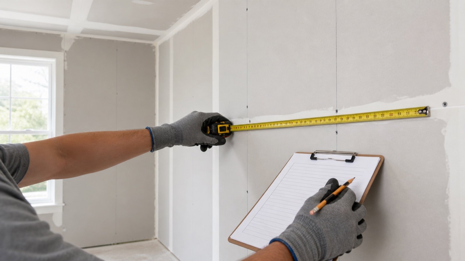
Use several observations and record uncertainty. One detector reading, fastener line or exposed bay does not prove that every stud follows one repeated grid.
- Check both sides for switches, outlets, trim fasteners and known panel joints.
- Use a suitable detector according to its instructions and verify from more than one direction.
- Confirm with a small permitted inspection opening or other accepted method before critical drilling or loading.
- Expect interruptions at windows, doors, corners, intersections, plumbing, blocking and repairs.
- Check for electrical, plumbing and other concealed services before cutting or fastening.
- Have altered, damaged or load-bearing work assessed when the condition is uncertain.
An existing wall can contain a changed layout, mixed member sizes or added backing. Record measured locations instead of forcing the observations onto a 16 in or 24 in template.
Which spacing mistakes affect the estimate?
- Selecting 16 in or 24 in from habit instead of the accepted project source.
- Checking the structural table but not the covering or tested assembly.
- Calling 400 mm equal to 16 in or 600 mm equal to 24 in.
- Counting clear gaps between stud faces as on-center spacing.
- Adding another end stud when the wall already ends on-grid.
- Omitting the physical end position on an off-grid run.
- Combining separate runs before rounding.
- Claiming a whole-project saving from the field-stud reduction alone.
- Ignoring attachments, backing, openings and aligned load paths.
- Applying one observed bay to an entire existing wall.
How do you carry the approved spacing into a takeoff?
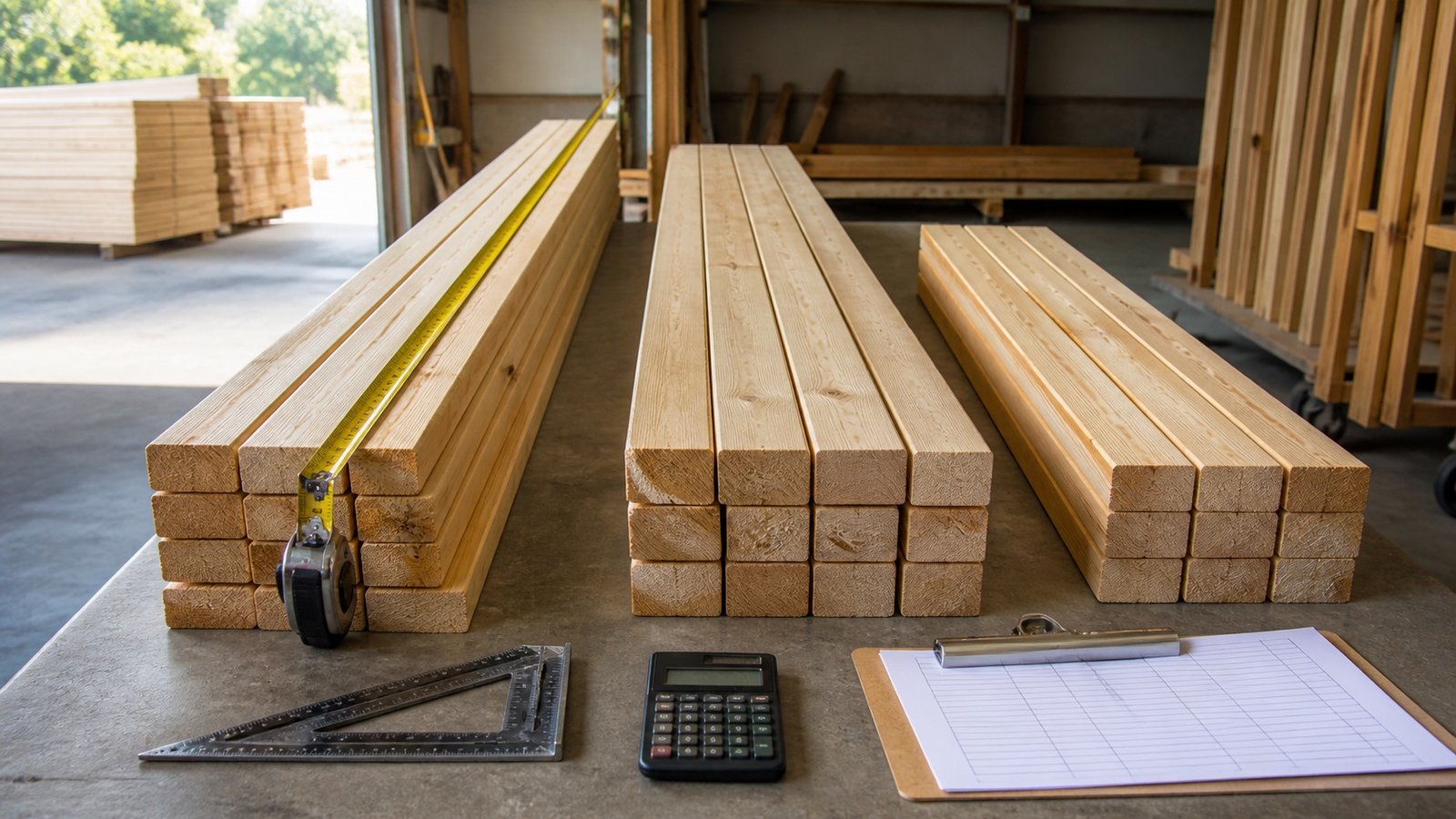
Enter each unique straight run and its approved on-center value in the Wall Stud Calculator. Add only the full studs supported by the corner, intersection, opening and backing ledger, then apply a documented allowance and deduct usable matching stock.
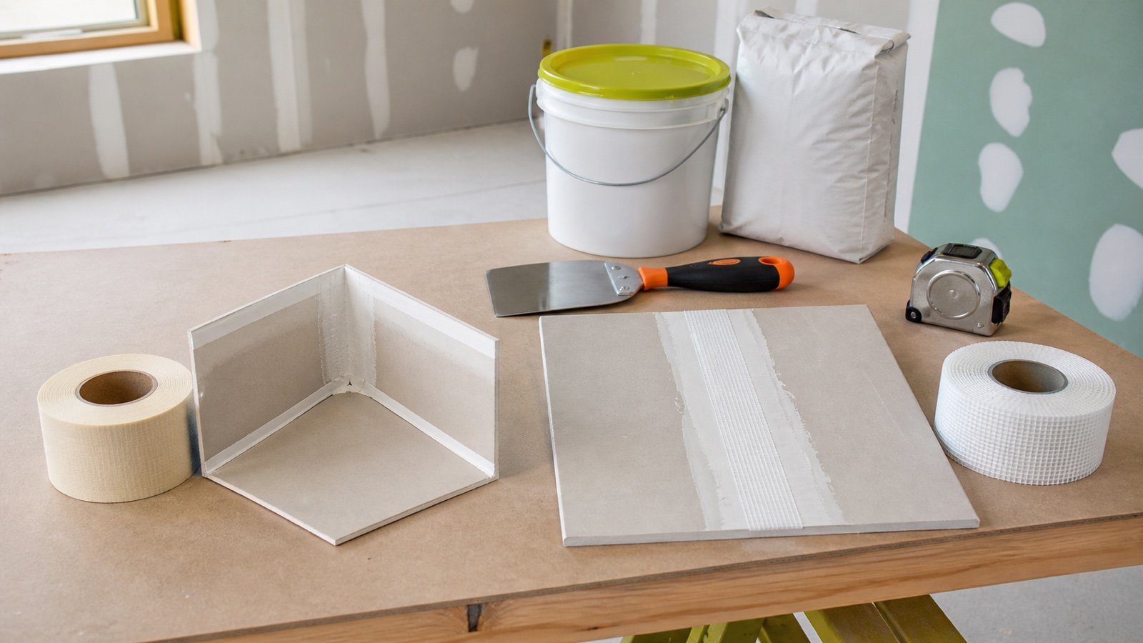
Use the Drywall Calculator for panel-area checks. The drywall sheet size and coverage chart helps separate nominal panel area from layout fit, while the drywall material takeoff worksheet keeps panels, framing and accessories on traceable rows.
Return to the Drywall planning hub for the current framing, panel, joint, compound, screw and corner-bead workflow.
Safety, design and project limits
This guide compares spacing records and field quantities. It does not design a wall, size members or headers, check loads, verify bracing, specify fastening, approve alterations or establish fire, sound, moisture, exterior and movement performance.
Follow current drawings, specifications, product instructions, temporary-bracing procedures and the locally adopted code. Structural walls, tall walls, large openings, unusual loads, high-wind conditions and altered construction can require a qualified designer or engineer.
Review the calculation methodology or report a formula, source or page issue through the corrections route.
Sources and source scope
- 2024 IRC Chapter 6, Wall Construction: model-code conditions connecting stud size, wall height, loads and maximum spacing.
- Gypsum Association, Spacing of Framing Members, and GA-216 overview: variables and application scope for gypsum panel support.
- American Wood Council, Lumber Studs: conventional wood-framing context and condition-dependent spacing examples.
- Building America Solution Center, Advanced Framing: Minimum Wall Studs: coordinated 24 in advanced-framing context and jurisdictional checks.
- NIST Handbook 44, current 2026 edition: official Appendix C conversion reference.
Source scope: the IRC page supports its stated model-code edition and conditions; local adoption and amendments control project use. Gypsum Association sources address panel application. AWC gives general wood-framing context. Building America describes a coordinated efficiency system. NIST supports unit conversions. None of these sources approves one spacing for an unidentified wall.
Review note: Saleem Sial owns the research and editorial record. Source checks, independent calculation fixtures, content tests, build validation, link crawl, schema review and rendered QA form the internal publication gate. Waseem Sial, External Reviewer and Engineer, is listed for ongoing external review; no completed review date is claimed.