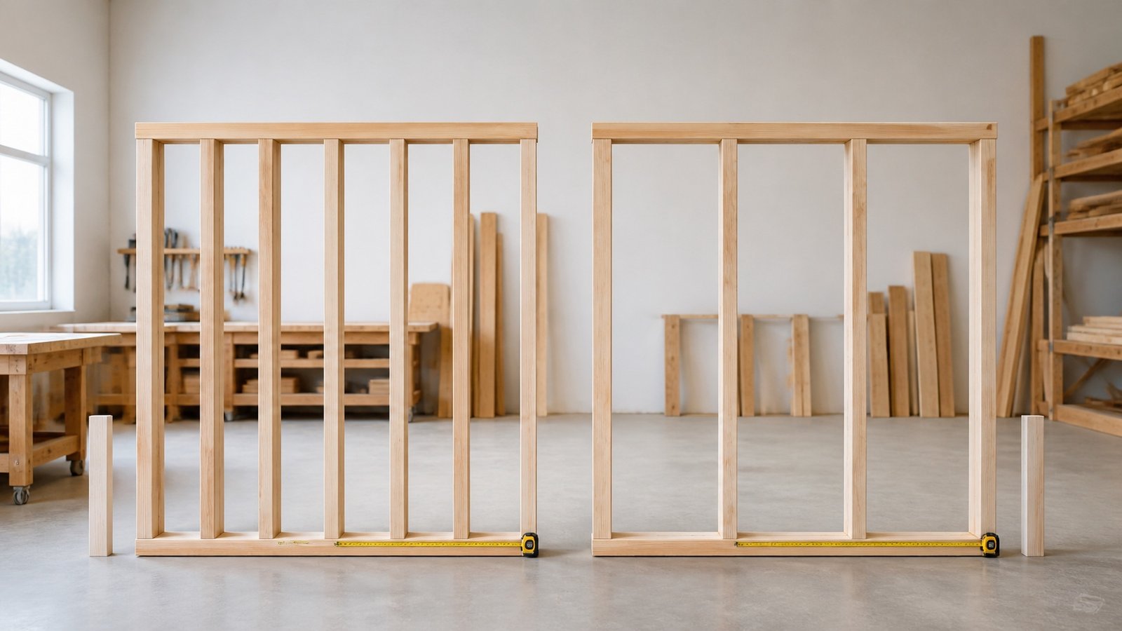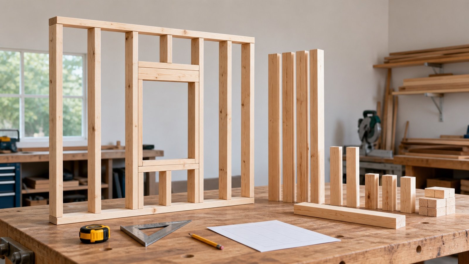
A reliable stud layout starts with one accepted wall run, one approved spacing and one clear measurement origin. The marks on the plates should let another person place every field stud without guessing which side of a line to use.
The layout also needs an honest end condition. A wall that stops between grid marks has a shorter closing bay, while a wall that ends on the grid already has its final position.
How do you lay out wall studs?
Confirm the wall-run endpoints and layout direction, pair the top and bottom plates, and mark each approved on-center position from the same origin. Convert each center position to a stud-edge line with the actual member width, mark the placement side, and add the physical closing position only when the wall end falls between grid marks.
- Check the current drawing, wall ID, plate length and approved spacing.
- Choose the accepted origin and measurement direction.
- Stack or pair the matching plates in the same orientation.
- Mark openings, corners, intersections and special backing from their approved details.
- Calculate the common-stud center positions.
- Offset each center by half the actual member face width to mark the chosen edge.
- Square each line across both plates and mark the placement side consistently.
- Check the final full spacing mark and closing bay.
- Record extra framing separately before calculating the purchase quantity.
Use the Wall Stud Calculator to check field positions, final-bay width, separate identical runs, approved extra studs, allowance and usable stock.
Which information should be confirmed before marking the plates?
Confirm the wall geometry and the source that controls the framing. A plate length and familiar spacing are not enough when the wall has a shifted origin, opening, corner, intersecting partition or panel-support requirement.
| Input | Record | Why it matters |
|---|---|---|
| Wall ID and revision | Level, room, wall type and current drawing date | Prevents marks from an obsolete plan reaching the plates |
| Run limits | Accepted start and physical end | Controls length and closing condition |
| Layout origin | Building grid, outside face, inside face or other accepted reference | Controls every grid position |
| Direction | Left to right or right to left as viewed from a named side | Prevents mirrored edge marks |
| On-center spacing | Approved value and source reference | Sets the repeated center grid |
| Member face width | Actual width along the layout direction | Sets the edge-line offset |
| Openings and details | Rough-opening, corner, tee, backing and assembly references | Identifies members outside the plain field grid |
| Panel or sheathing layout | Accepted direction, edge support and joint locations | Checks whether the chosen origin supports the specified covering |
Stud spacing can vary with wall role, member size, height, loads, sheathing or panel application and local requirements. Copy the value from the accepted project source. This guide does not select 12 in, 16 in, 24 in, 300 mm, 400 mm, 450 mm or 600 mm spacing for the work.
What is the difference between an on-center mark and a stud-edge line?
An on-center position locates the middle of the member. A stud-edge line locates one face of that member so it can be placed without finding the center of every piece.
Center position = grid index × approved spacing
Edge line for right-side placement = center position − actual member face width ÷ 2
If the accepted convention places the stud on the other side of the line, reverse the half-width offset. Mark an X or another documented symbol on the placement side and use the same convention across both plates.
For a 1.5 in-wide member on a 16 in center grid, a right-side edge line is 16 − 0.75 = 15.25 in from the origin. The next lines are 31.25 in, 47.25 in and so on. That 15-1/4 in mark is one example tied to a 1.5 in face, a 16 in grid and a stated placement side. Change any of those inputs and the edge line changes.
A calculator can return centers at 16 in intervals while the physical plate shows edge lines offset by half the member width. Calling both numbers “stud marks” makes a field check harder.
Where should the wall-stud layout start?
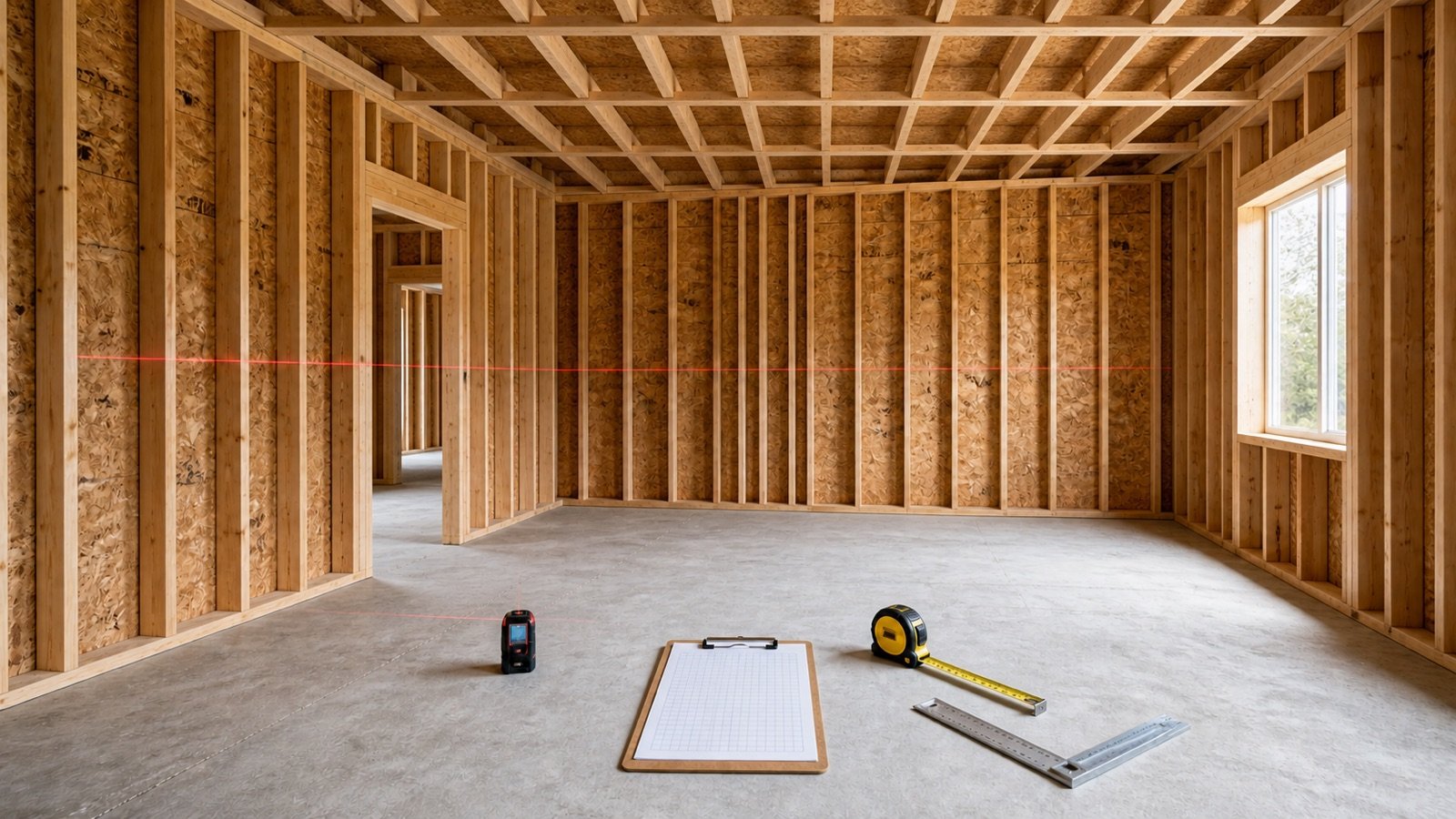
Start from the origin named by the accepted building or wall-layout plan. The cut end of an isolated plate is a usable origin only when that end matches the intended project reference.
A continuous exterior grid may need to carry across corners, jogs and intersecting walls so sheathing, floor framing, roof framing or panel joints land where the design expects them. An interior wall placed between other walls can also have a plate end that sits away from the building origin.
- Write the origin on the takeoff and on the plate bundle.
- Name the viewing side and measurement direction.
- Record any distance from the building grid to the plate end.
- Keep a shifted or reversed run as a separate calculation.
- Check panel-edge, opening and load-path requirements before accepting the common grid.
If the project documents do not establish the origin, stop and obtain the layout decision from the responsible person. Moving the origin after the openings and common studs are marked can shift every downstream line.
How should top and bottom plates be marked together?
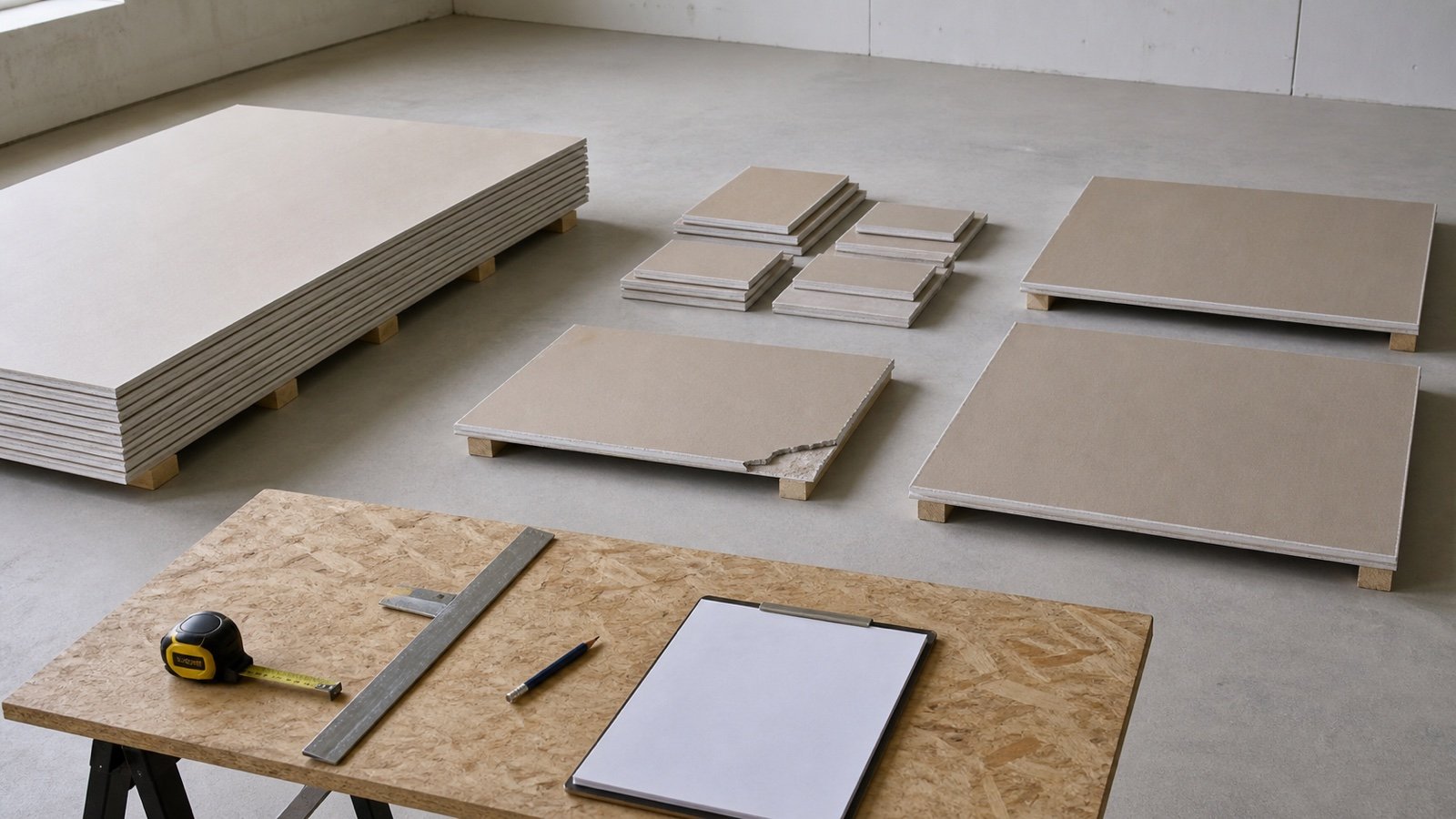
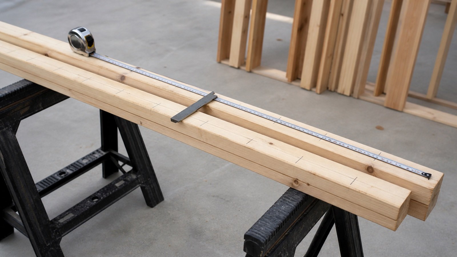
Pair the matching plates in the same orientation and transfer each accepted line across both pieces with a square. This keeps top and bottom positions aligned and leaves one visible set of checks.
The SkilledTradesBC Level 1 carpenter module describes determining plate length and stud spacing from project information, tacking or holding the plates together, and transferring layout lines across them. Its example also uses an X to identify the side of an edge line where the member belongs.
- Confirm both plates belong to the same wall and revision.
- Align the accepted origin ends, not simply the nearest cut ends.
- Orient crowns, faces and labels according to the project method.
- Secure the pair so it cannot creep while marks are transferred.
- Mark special framing before common studs when the workflow requires it.
- Square every accepted edge line across both plates.
- Write the same placement symbol on both pieces.
- Separate the plates only after a second person or documented self-check confirms the sequence.
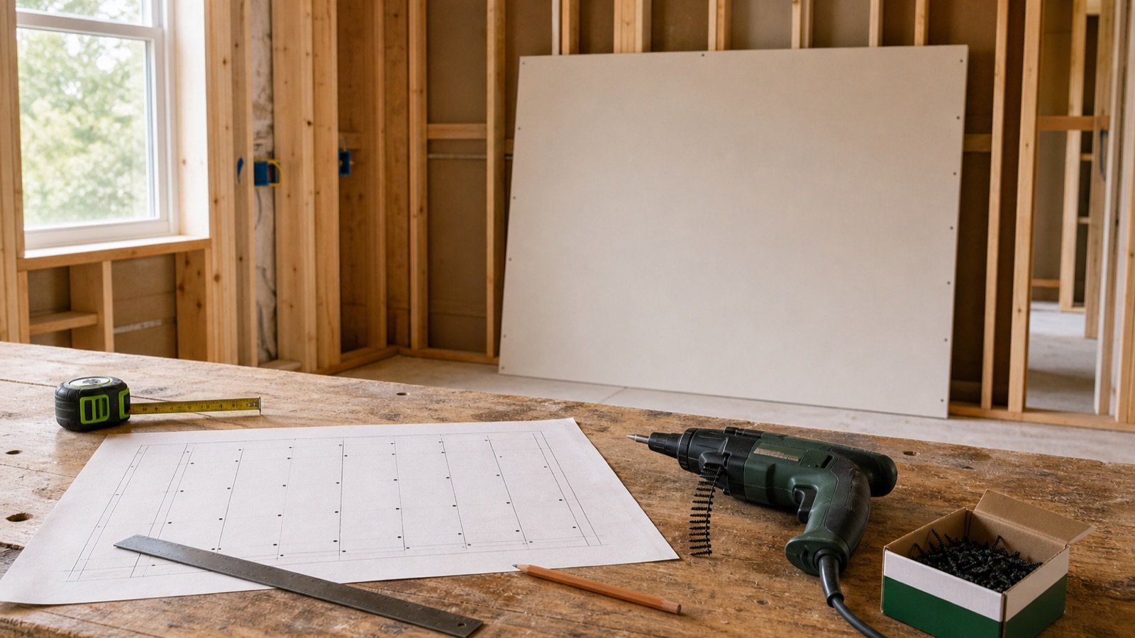
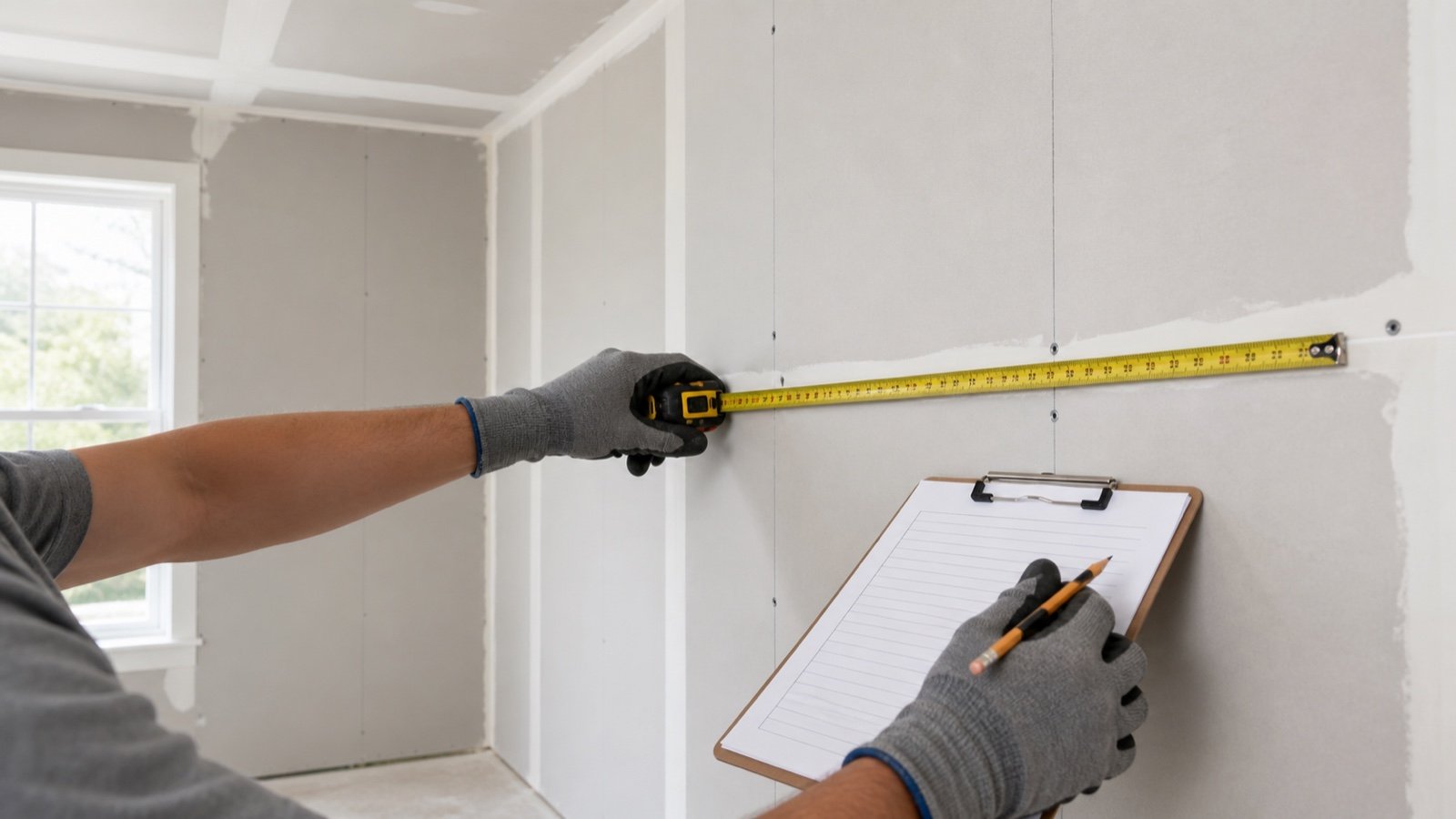
The article image shows the transfer workflow. It does not identify an approved spacing or structural detail for a project.
How do you calculate the closing bay?
Divide the wall length by the approved spacing and keep the remainder. A positive remainder is the distance from the last full grid mark to the physical wall end.
Full intervals = floor(wall-run length ÷ approved spacing)
Grid remainder = wall-run length − full intervals × approved spacing
When the remainder is greater than 0, add a closing position at the wall end and report the remainder as the final bay. When the remainder is 0, the end already lies on the spacing grid; the final bay is one full spacing and another closing position would duplicate the end stud.
Worked example: a 10 ft run at 16 in on-center
A 10 ft run is 120 in long. With an approved 16 in spacing, floor(120 ÷ 16) gives 7 full intervals. Their centers after the origin are 16, 32, 48, 64, 80, 96 and 112 in.
The remaining distance is 120 − 112 = 8 in. Count the start position, 7 full grid positions and the physical end position, giving 9 field studs. With a 1.5 in member placed to the right of its line, the 7 grid edge marks are 15.25, 31.25, 47.25, 63.25, 79.25, 95.25 and 111.25 in.
The closing member at 120 in follows the accepted wall-end detail. Do not force that physical end onto the repeated center grid or assume its pencil line uses the same relationship as the interior field marks.
Worked example: a 24 ft exact-grid run
A 24 ft run is 288 in. At an approved 16 in spacing, 288 ÷ 16 gives 18 full intervals and 19 positions from 0 through 288 in. The final position is already on-grid, so the layout does not add another closing stud. The last bay is 16 in.
Why should separate wall runs keep separate layouts?
Every separate run has its own origin and physical end. Pooling lengths before rounding can remove positions that must occur at each break.
One 10 ft run at 16 in spacing has 9 field positions. Two separate 10 ft runs have 18. One continuous 20 ft run has 16 positions because its grid continues through the point where the separate runs would end and restart.
| Wall ID | Length | Origin | Spacing | Final bay | Field positions |
|---|---|---|---|---|---|
| W-01 | 10 ft | Grid A, east | 16 in | 8 in | 9 |
| W-02 | 10 ft | Grid C, west | 16 in | 8 in | 9 |
| Combined check | 20 ft measured | 2 origins | 16 in | 2 separate bays | 18 |
Use the calculator's identical-run field only when the lengths, origins, spacing and end rules match. Run another calculation when any of those values changes.
How should doors, windows, corners and intersections be handled?
Keep the common grid visible, then apply the accepted detail for each interruption. Record removed field pieces, full-height additions and cut members separately so the plain spacing calculation remains auditable.
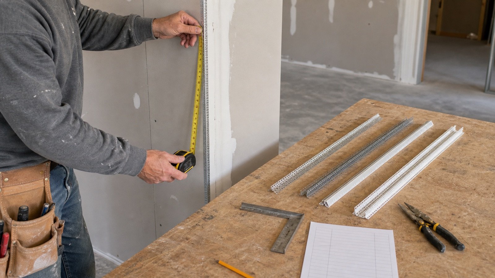
The American Wood Council notes that corners and partition intersections can use multiple studs, nailing strips or metal clips for finish backing. The selected project detail controls the quantity. A fixed “add 3 studs per corner” rule can overcount one system and undercount another.
| Condition | Keep on the layout | Record separately |
|---|---|---|
| Door or window | Common grid reference through the opening | King, jack or trimmer, cripple, sill and header detail |
| Outside corner | Run origin and physical end | Corner assembly and backing method |
| Partition tee | Intersection location | Stud pack, ladder backing, clip or approved alternative |
| Cabinet or fixture backing | Reference dimensions | Blocking type, elevation and stock length |
| Rated or acoustic wall | Complete wall ID | Tested assembly, joints, resilient elements and fastening details |
The 2024 IRC Chapters 6 and 7 provide model-code examples in which stud spacing, openings and wall-covering support depend on stated conditions. The locally adopted edition, amendments, drawings, specifications and accepted design control the work.
How should metric layouts be checked?
Use millimetres for both run length and spacing within the layout calculation. Do not replace an approved metric module with a rounded imperial value or replace an imperial module with a rounded metric value.
A 4.8 m run equals 4,800 mm. At an approved 400 mm spacing, it has 12 intervals and 13 positions including both ends. NIST's unit tables support the exact relationships 1 ft = 12 in and 1 in = 25.4 mm, but a converted dimension does not change the product or module named by the project.
For edge lines, measure the actual member face width in the same unit. A 38 mm member placed to the right of a 400 mm center line uses an edge mark at 381 mm from the same origin. Confirm the product's actual dimension instead of assuming every nominal label has the same finished width.
How do you check a completed plate layout?
Recalculate from the recorded origin and compare the sequence on both plates before assembly. A total stud count cannot reveal a mirrored layout, one missed mark or an edge line placed on the wrong side.
- Confirm wall ID, revision, origin and direction on both plates.
- Measure the plate length independently from the accepted endpoints.
- Check several center positions from the origin rather than chaining from the previous pencil line.
- Verify the half-width offset and placement symbol.
- Compare opening and special-framing marks with their detail references.
- Confirm the last full grid position and measured closing bay.
- Check that top and bottom lines align while the plates remain paired.
- Reconcile the field-position count with the calculator result.
After assembly, the site method must still check wall position, straightness, plumb, square, bracing and connections. Correct spacing marks do not prove that the wall is structurally complete or installed in the right location.
Which layout mistakes change the result?
- Choosing 16 in or 400 mm spacing from habit instead of the project source.
- Starting from a plate end that does not match the accepted building origin.
- Measuring center positions but placing the same stud edge on those numbers.
- Using a 15-1/4 in line with a different member width, spacing or placement side.
- Changing measurement direction without changing the edge-line convention.
- Chaining every mark from the previous line and carrying a small error across the wall.
- Adding a duplicate closing stud when the end already lies on-grid.
- Omitting the physical end position when the wall stops between grid marks.
- Pooling separate wall lengths before rounding.
- Removing grid references through openings before the opening detail is applied.
- Using fixed extra counts for every corner, tee or opening.
- Separating paired plates before checking transferred marks.
How does the layout become a material takeoff?
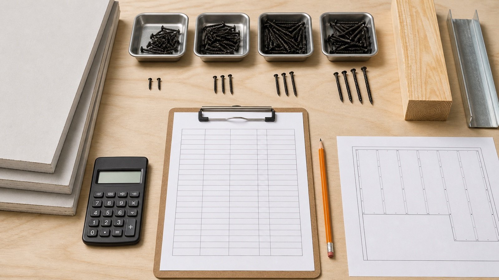
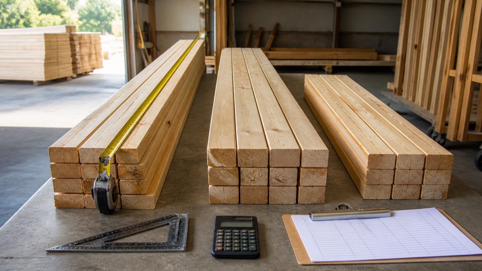
Enter each unique run in the Wall Stud Calculator. Add only the full pieces supported by the opening, corner, intersection and backing ledger, then apply a documented allowance and deduct usable matching stock.
Keep short cripples, blocking, plates, headers and other products on their own rows when their stock lengths or specifications differ. Carry the accepted quantities into the drywall material takeoff worksheet.
Use the Drywall Calculator for panel-area and rectangular-grid checks. Return to the Drywall planning hub for the current panel, joint, compound, screw, corner-bead and framing workflow.
Safety, design and project limits
This guide explains quantity and plate-marking records. It does not design a wall, choose stud size or grade, size headers, verify loads, approve bracing, set fastening, check notches or holes, or establish fire, sound, moisture, exterior and movement performance.
Follow current drawings, specifications, product instructions, temporary-bracing procedures, site safety rules and the locally adopted code. Structural walls, tall walls, large openings, unusual loads and changes to existing construction can require a qualified designer or engineer.
The calculation methodology explains unit, rounding and independent-fixture checks. Report a source, arithmetic or layout issue through the corrections route.
Sources and source scope
- SkilledTradesBC Level 1 Carpenter Module H3: plate preparation, project spacing, paired-plate transfer, edge-line marking and the stated 16 in example.
- American Wood Council, Lumber Studs: stud role, spacing context, grade marks and corner or intersection backing options.
- 2024 IRC Chapter 6, Wall Construction: model-code examples for condition-dependent stud spacing and opening framing.
- 2024 IRC Chapter 7, Wall Covering: model-code examples connecting wall-covering conditions with framing-member spacing.
- NIST Handbook 44, current 2026 edition: official Appendix C unit-conversion reference.
Source scope: SkilledTradesBC supports its vocational layout sequence and example. AWC supplies general wood-framing context. The IRC links cover their stated model-code conditions, while local adoption and project documents control use. NIST supports unit relationships. None of these sources approves this page's example origin, project spacing, extra-member count or finished wall design.
Review note: Saleem Sial owns the research and editorial record. Source checks, independent arithmetic, editorial review, internal-link review, build validation, crawl, schema review and rendered QA form the internal publication gate. Waseem Sial, External Reviewer and Engineer, is listed for ongoing external review; no completed review date is claimed.