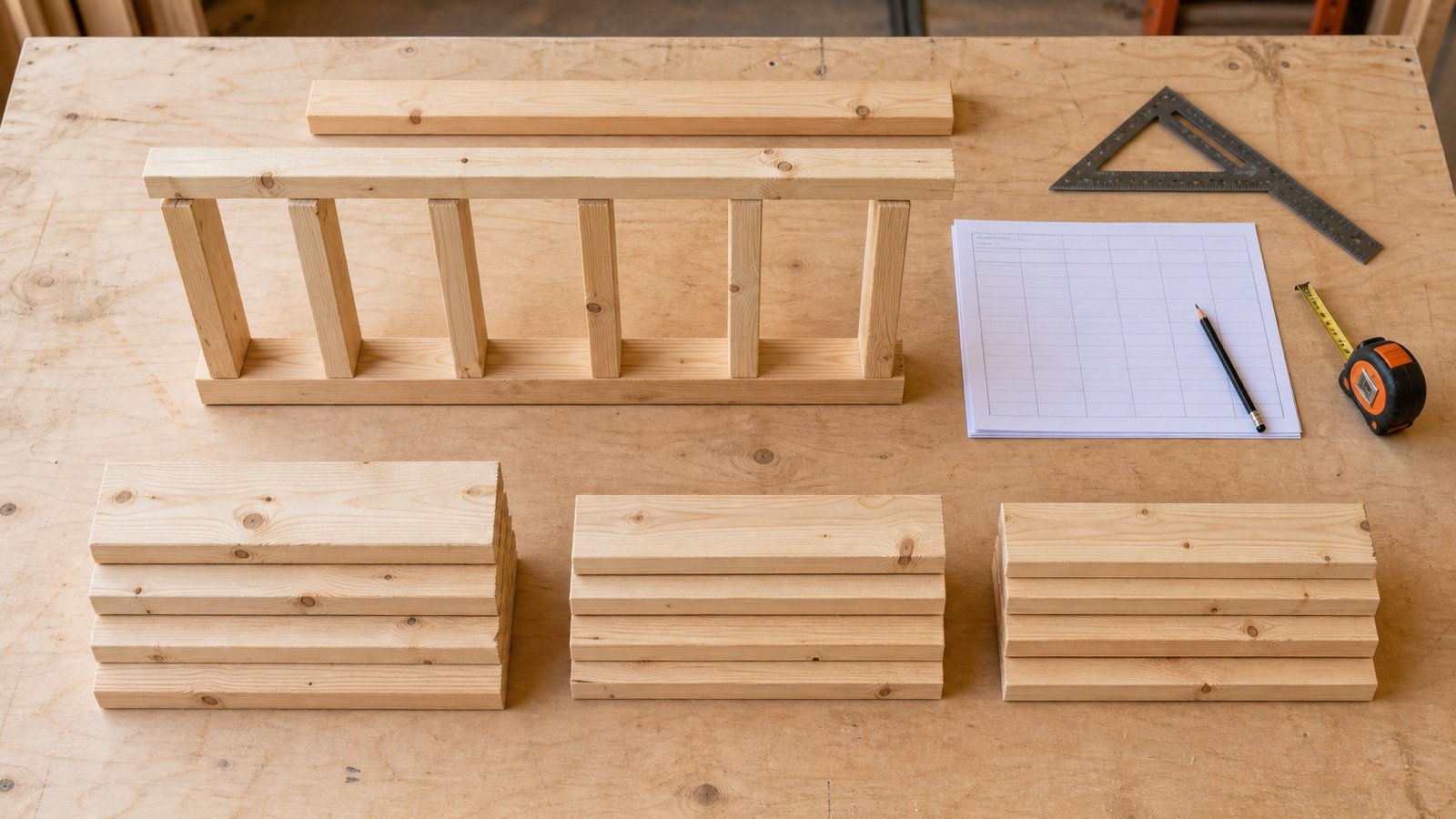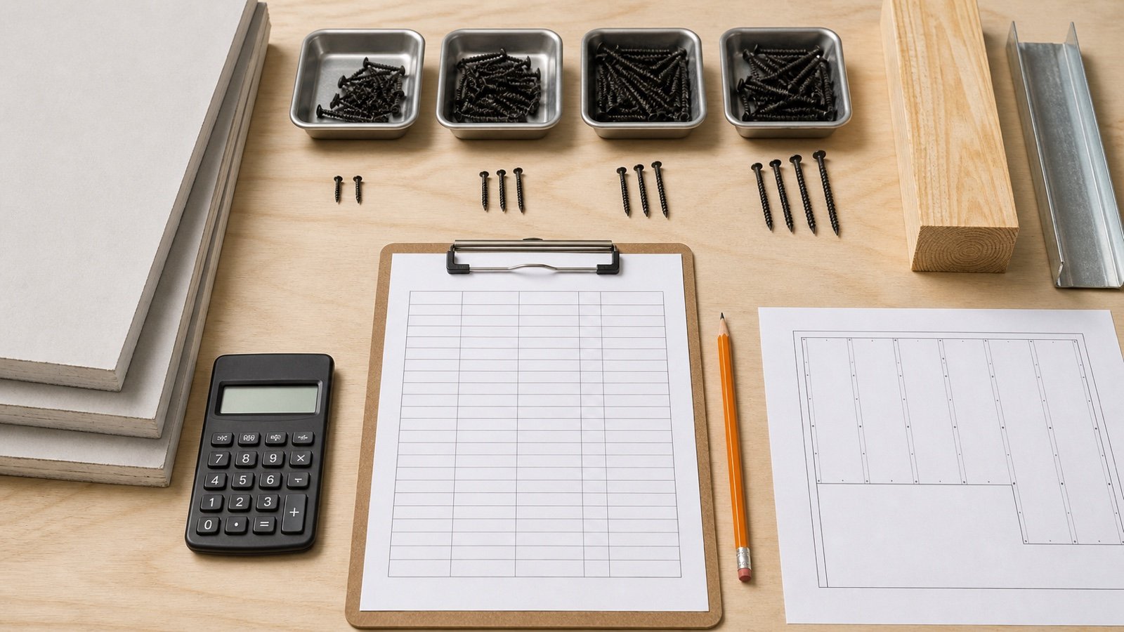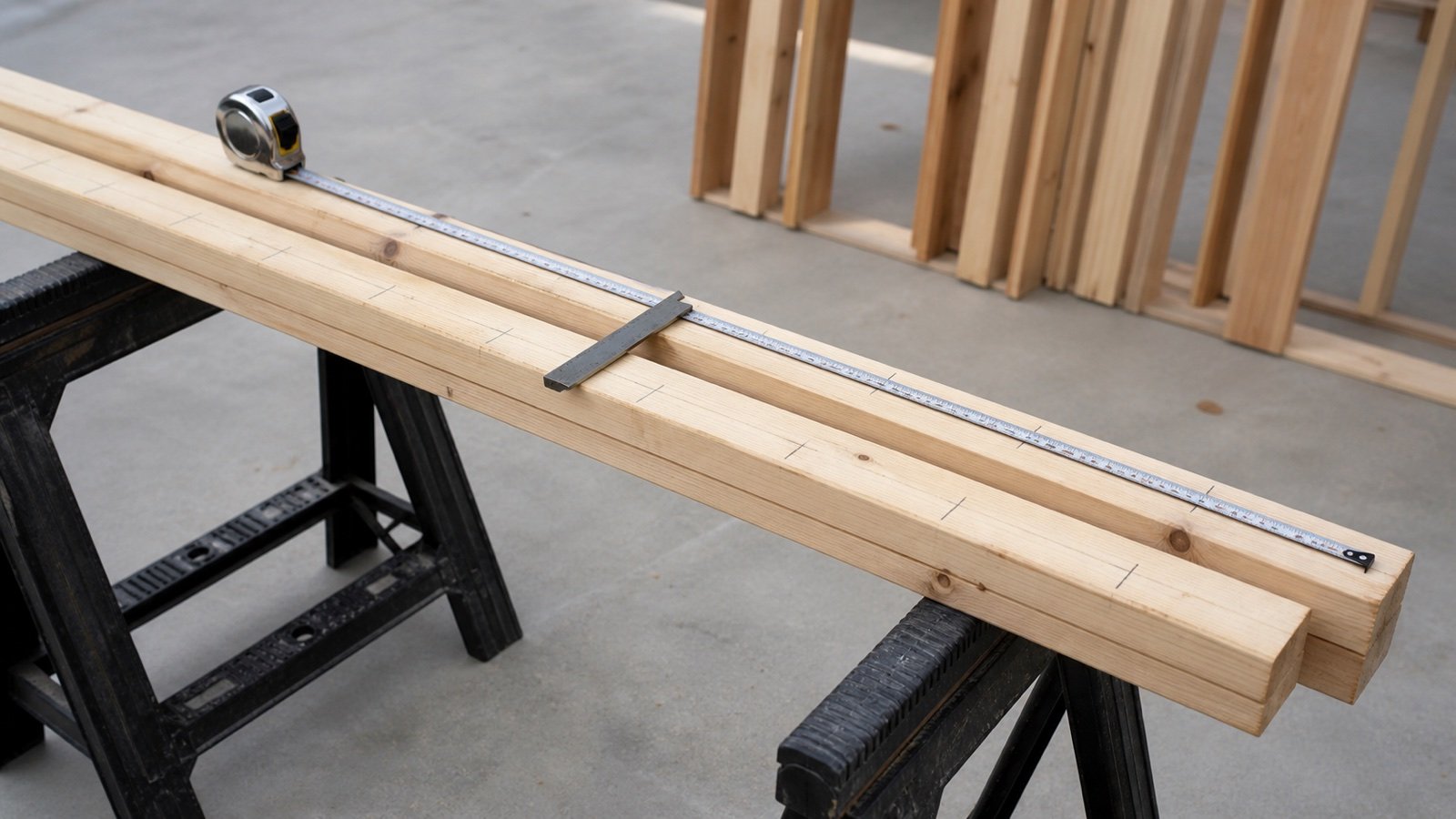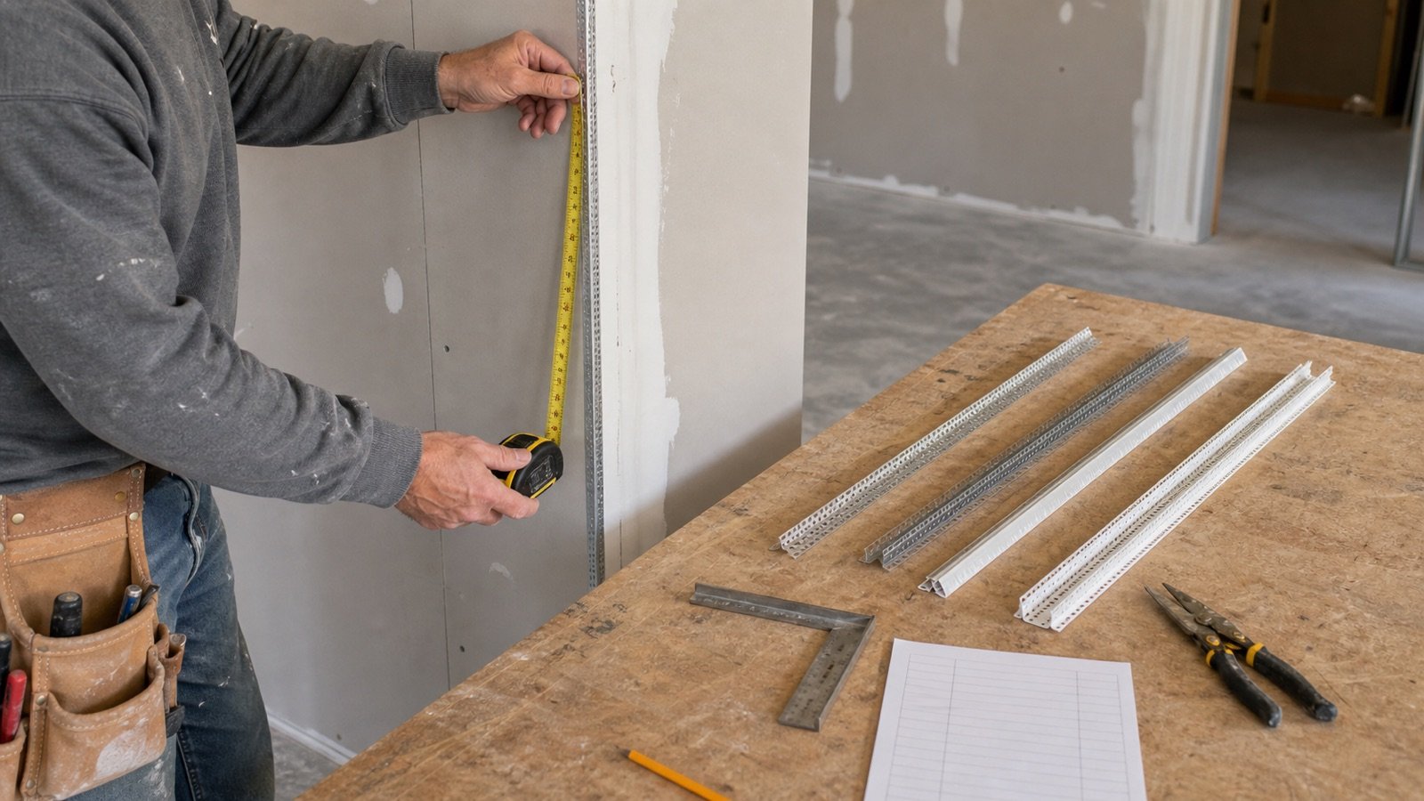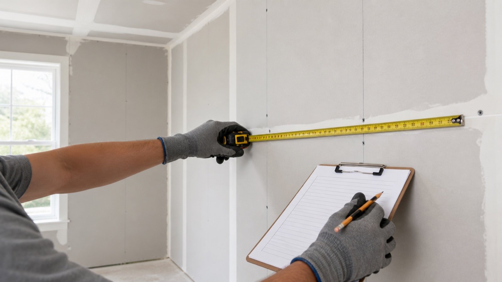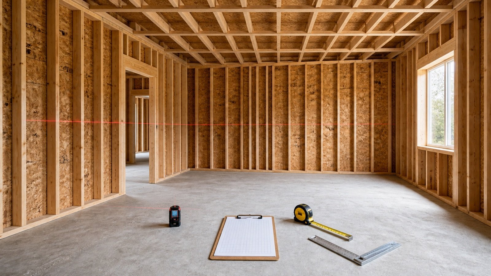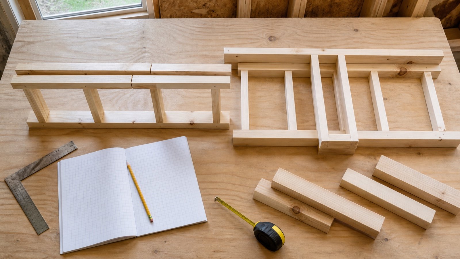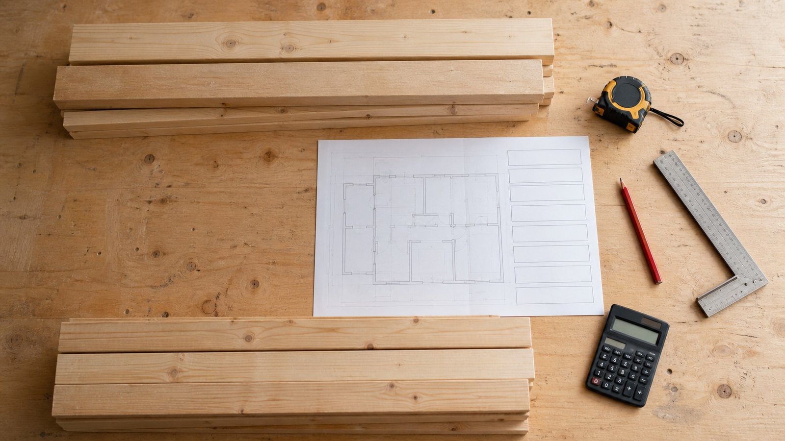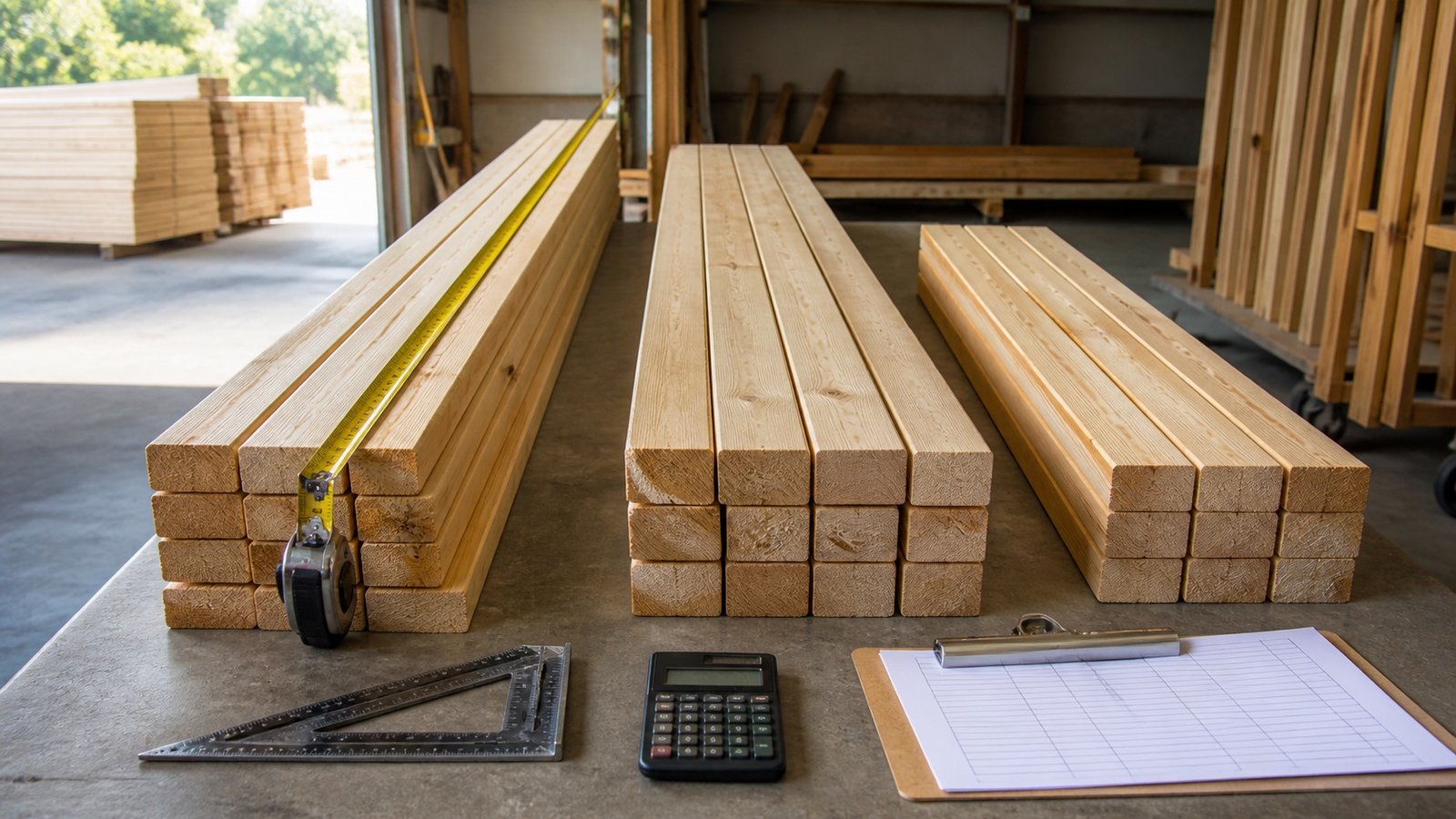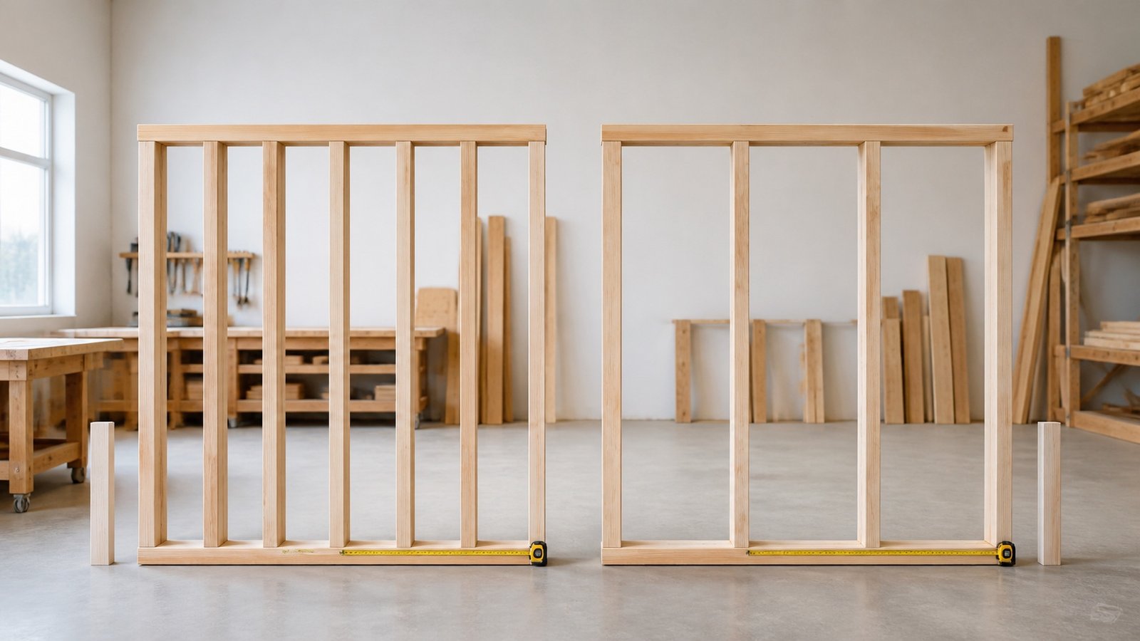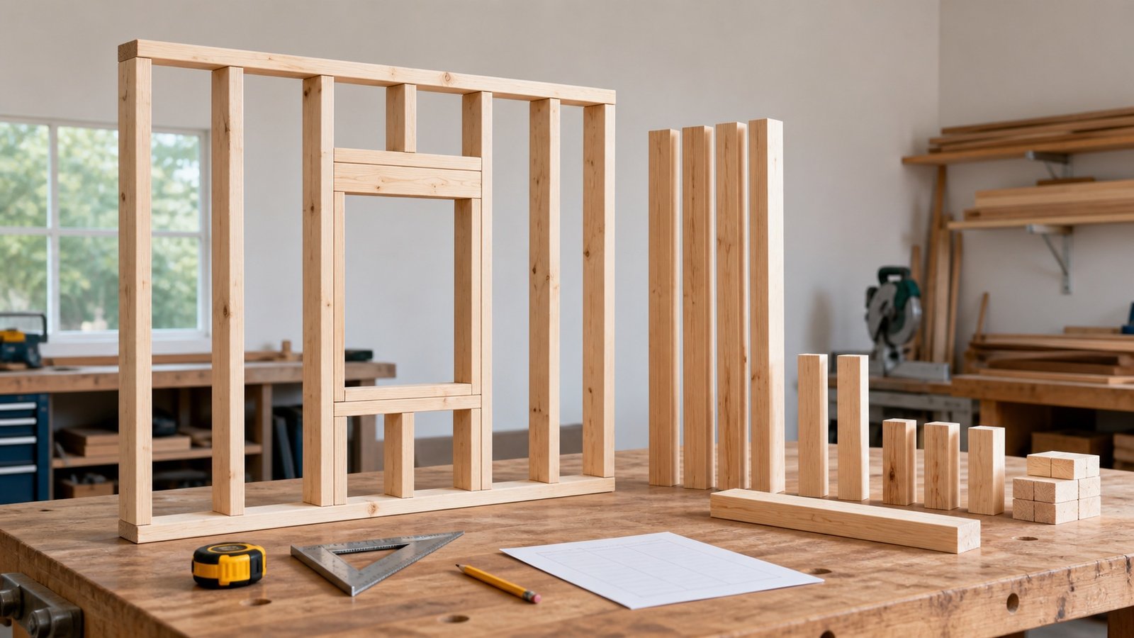
A plain spacing calculation gives you field positions along a straight wall. A purchase takeoff needs another record for openings, corners, intersecting walls, backing and pieces cut to different lengths.
Build that record wall by wall. You can then see which grid studs remain, which positions disappear inside an opening and which detail members need new stock.
How do you prepare a wall stud takeoff?
Calculate the field positions for each straight wall run, then reconcile every accepted framing detail against those positions. Keep retained or reclassified studs inside the field count, subtract removed positions, add new full-height members once, and list short or different-stock pieces on separate rows.
Installed full-height studs = field positions − removed field positions + new full-height pieces
Net full-height adjustment = new full-height pieces − removed field positions
The detail schedule, framing elevation or accepted design supplies the piece requirements. The worksheet records them; it does not decide how many king studs, jack studs, cripples, corner studs or backing pieces a wall needs.
| Column | Record | Check |
|---|---|---|
| Wall identity | Level, room, wall ID and current drawing revision | One row points back to one wall |
| Field layout | Run length, origin, direction, spacing and field positions | Matches the accepted layout source |
| Detail reference | Opening, corner, tee, backing or load detail number | Current accepted revision |
| Retained or reclassified | Grid positions that stay in the wall under another role | Count remains in the field subtotal |
| Removed | Grid positions omitted or shortened by the detail | Subtract once |
| New full-height | Members absent from the field-grid count | Add once |
| Short or different stock | Jacks, cripples, sills, blocking, headers and plates by size and cut length | Keep outside the full-height total |
| Order adjustment | Documented allowance and usable matching stock | Apply after the reviewed base count |
Which project information belongs at the top of the worksheet?
Record the information that another person needs to reproduce the count. A total with no wall IDs, dimensions or detail references cannot show whether the estimator used the current plans.
- Project, building, level, area and worksheet number.
- Prepared-by and checked-by names with dates.
- Drawing, specification and detail revisions.
- Wall type, material, nominal size, actual product and required full-height stock length.
- Approved on-center spacing and layout origin.
- Bearing, nonbearing, exterior, braced, rated or other wall classification stated by the documents.
- Opening IDs and rough-opening dimensions from the accepted schedule.
- Unresolved questions, responsible decision-maker and response status.
Use a new row when wall height, stud product, grade, treatment, spacing, assembly or stock length changes. Combining unlike products can produce a correct piece total and an unusable order.
How should the plain field count be recorded?
Count each straight run from its accepted origin to its physical end. Include the starting position, every full spacing position and an off-grid closing position when the wall ends between grid marks.
Use the Wall Stud Calculator for this baseline. The wall-stud spacing guide explains how to verify the entered spacing, and the wall-stud layout guide covers center positions, edge lines and closing bays.
A 12 ft wall at 16 in on-center has 10 field positions. A separate 10 ft wall has 9. Their takeoff starts at 19 positions, even when the walls use the same stud product.
Draw or list the grid through openings before applying the detail. This gives you a visible reference for positions that remain, change role or disappear.
How do openings change the full-height count?
An opening can remove common field positions, retain some positions as full-height kings and add full-height members that were absent from the grid. Jack or trimmer studs, cripples, sills and headers often use different lengths or products, so they need separate rows.
The DOE Building America opening guide identifies the full-length member beside an opening as a king stud. It describes jack studs supporting the header, a sill below a window and cripples above or below an opening. Its limits on extra members belong to the named advanced-framing system and its accepted plans.
| Record | Treatment in the full-height total | Separate takeoff row |
|---|---|---|
| Grid stud remains as a king | Retain and reclassify; do not add it again | Role and opening ID |
| Grid position falls inside the clear rough opening | Remove from the full-height field subtotal | Removal position and reason |
| New king or other full-height jamb member | Add when the field grid did not already count it | Size, length and detail reference |
| Jack or trimmer | Exclude from full-height subtotal when it is shorter | Cut length, count and bearing detail |
| Cripple | Exclude unless the cut plan assigns full-length stock | Upper or lower location and cut length |
| Header or sill | Exclude from stud subtotal | Approved assembly, plies, size and cut length |
APA's DT-AF-12 shows one single-ply load-bearing header configuration with code-dependent king and jack stud requirements. It confirms that opening support belongs to a named detail. It does not supply a universal count or header size for this worksheet.
How should corners and partition intersections be counted?
Count the exact accepted assembly and subtract any member already represented by the field grid. Corner and intersection methods vary because the framing may need to connect walls, support finishes, carry loads, retain insulation space or satisfy a tested assembly.
The American Wood Council notes that corners and partition intersections can use multiple studs, nailing strips or metal clips. DOE Building America documents several interior/exterior intersection options, including ladder blocking, a full-length nailer, or a connector and drywall clips. Its corner guide also shows different insulated corner configurations.
| Detail ID | Required by accepted detail | Already in field grid | New full-height | Other stock |
|---|---|---|---|---|
| C-01 | Named corner assembly | End or grid member retained | Assembly total less retained full-height members | Clips, nailer or blocking when specified |
| T-01 | Named partition-intersection method | Host-wall member retained | Full-height support absent from the grid | Ladder blocks, plate or clips when specified |
| B-01 | Fixture or panel-edge backing detail | Matching grid support retained | Full-height backing only when specified | Short blocking or sheet backing by cut size |
A fixed “add 2 studs per corner” entry can miss one accepted system and overcount another. Write the detail ID in the same row as the quantity.
Worked example: 2 wall runs with a door and window
This fixture uses stated example details to test the worksheet arithmetic. The counts do not approve a corner, intersection, door or window design for another project.
W-01: 12 ft wall with one corner and one door
The approved spacing is 16 in on-center, giving 10 plain field positions. The accepted corner detail retains the wall-end grid member and requires 2 new full-height pieces. The door elevation removes 1 field position, retains another as a king and requires 1 new full-height king.
| Row | Field positions | Removed | New full-height | Running total |
|---|---|---|---|---|
| Plain 12 ft grid | 10 | 0 | 0 | 10 |
| Corner C-01 | 1 retained | 0 | 2 | 12 |
| Door D-01 | 1 retained as king | 1 | 1 | 12 |
W-01 has 12 installed full-height studs: `10 − 1 + 3 = 12`. Its net full-height adjustment is `+2`. The 2 jack or trimmer pieces and approved header assembly stay on separate rows.
W-02: 10 ft wall with one intersection and one window
The 16 in grid gives 9 field positions and an 8 in closing bay. The accepted intersection retains 1 grid member and adds 1 full-height piece. The window elevation removes 2 grid positions, retains another as a king and adds 1 full-height king.
| Row | Field positions | Removed | New full-height | Running total |
|---|---|---|---|---|
| Plain 10 ft grid | 9 | 0 | 0 | 9 |
| Intersection T-01 | 1 retained | 0 | 1 | 10 |
| Window WN-01 | 1 retained as king | 2 | 1 | 9 |
W-02 finishes with 9 installed full-height studs: `9 − 2 + 2 = 9`. Its net full-height adjustment is 0. Separate rows list 2 jack or trimmer pieces, 4 cripples, 1 sill and the approved header assembly.
Project reconciliation
| Quantity | Calculation | Result |
|---|---|---|
| Plain field positions | 10 + 9 | 19 |
| Removed positions | 1 + 2 | 3 |
| New full-height pieces | 3 + 2 | 5 |
| Installed full-height studs | 19 − 3 + 5 | 21 |
| Example 5% allowance | ceiling(21 × 0.05) | 2 |
| Planning full-height studs | 21 + 2 | 23 |
| Example usable matching stock | 2 | 2 |
| Full-height studs to purchase | 23 − 2 | 21 |
The 5% allowance is a fixture input. Choose an allowance from the project's selection criteria, cut plan, handling conditions, planned changes and spare-stock policy.
How does the worksheet connect to the Wall Stud Calculator?
Run each wall separately in the Wall Stud Calculator. Enter the worksheet's nonnegative net full-height adjustment, then apply the documented allowance and verified matching-stock deduction.
- For W-01, enter 12 ft, 16 in spacing, 1 run and 2 approved extra studs. The calculator returns 12 base full-height studs.
- For W-02, enter 10 ft, 16 in spacing, 1 run and 0 approved extra studs. The calculator returns 9 base full-height studs.
- Add the accepted wall results only after confirming they use the same purchase product.
- Keep jacks, cripples, sills, blocking, plates and headers on their cut-list rows.
The calculator accepts 0 or a positive whole number for approved extras. When one wall has a negative net adjustment, keep its final installed total in the worksheet and use the calculator to verify the plain field grid. Do not offset that negative value against another wall's positive extras.
How should short pieces become a purchase order?
Group short pieces by product and cut length, then test them against available stock lengths. One full-length stud can supply several short pieces only when dimensions, saw kerf, defects, grade, treatment, orientation and the accepted reuse rules permit that cut plan.
| Piece role | Required record | Purchase check |
|---|---|---|
| Jack or trimmer | Opening ID, count, member size and exact cut length | Bearing and connection detail |
| Cripple | Upper or lower location, count and cut length | Grid, panel support and fastening |
| Rough sill | Opening ID, size, length and support | Product and connection detail |
| Blocking or backing | Location, purpose, size and count | Fixture, finish or assembly requirement |
| Header | Approved type, plies, size, length and bearing | Design reference; worksheet does not size it |
| Plate | Bottom and top plate schedule by run and stock length | Splices, laps, treatment and cut plan |
The SkilledTradesBC module separates detailed stock lengths when wall geometry changes and notes that scale drawings can support member-by-member counts. Its examples use Canadian practice. Use the same record discipline with the governing documents for your project.
How should allowance and usable stock be handled?
Apply allowance after the reviewed base quantity, then deduct stock that matches the required product and condition. Write the reason and the person who accepted the allowance.
Allowance pieces = ceiling(installed full-height studs × documented allowance / 100)
Purchase pieces = maximum(0, installed full-height studs + allowance pieces − usable matching stock)
- Inspect full-height stock for size, length, grade, species or product, treatment, moisture and visible condition.
- Keep unidentified, damaged or mismatched stock out of the deduction.
- Record short offcuts in the cut-stock ledger rather than counting them as full-height pieces.
- Apply supplier bundle or pack rounding after the piece requirement when the seller uses one.
- Keep reserve pieces separate from accidental over-ordering.
Use current supplier data for available lengths, grade, treatment, bundle quantity, price, delivery charges and return rules. The worksheet should retain the quote date and location.
How should revisions and existing walls be recorded?
Issue a revision row when the wall length, spacing, opening, detail or product changes. Preserve the previous quantity, show the added and removed pieces, and record whether procurement or installation has already occurred.
| Field | Example record |
|---|---|
| Revision trigger | Door D-01 moved 16 in on drawing A-104 Rev 4 |
| Layout effect | Grid positions rechecked from the accepted origin |
| Quantity change | Added, removed, recut and unchanged pieces listed separately |
| Material status | Not ordered, ordered, delivered, cut or installed |
| Disposition | Return, reuse, quarantine, scrap or retain as approved spare |
| Approval | Responsible person and response date |
For an existing wall, record observed members, inspection limits and concealed conditions. A detector reading or one exposed bay cannot establish the detail across the full wall. Check for concealed electrical, plumbing and other services before cutting or fastening.
Which takeoff mistakes change the purchase count?
- Combining separate wall lengths before calculating their start and end positions.
- Adding every king stud when a field-grid stud already remains in that role.
- Leaving grid positions inside a clear rough opening in the full-height subtotal.
- Subtracting an opening area without counting its accepted jamb, header, sill and cripple details.
- Using one fixed corner or tee addition across different wall systems.
- Counting short jacks and cripples as full-height pieces before preparing a cut plan.
- Mixing stud sizes, grades, treatments, lengths or wall types on one order row.
- Applying allowance before opening and detail reconciliation.
- Deducting offcuts or rejected stock as usable full-height members.
- Changing the worksheet date without checking a substantive revision.
How does the stud takeoff connect to drywall planning?
Carry accepted wall IDs, openings and backing locations into the Drywall Material Takeoff Worksheet. Use the Drywall Calculator for panel-area and rectangular-grid checks.
Framing and panel records should use the same wall identity and revision. Return to the Drywall planning hub for the current framing, panel, screw, tape, compound and corner-bead workflow.
Safety, design and project limits
This worksheet records quantities. It does not design a wall, size a stud or header, calculate loads, approve bracing, set bearing, specify fastening, verify notches or holes, or establish fire, sound, moisture, exterior and movement performance.
Follow current drawings, specifications, product instructions, temporary-bracing procedures, fall-protection requirements and the locally adopted code. Structural walls, tall walls, large openings, unusual loads and altered construction can require a qualified designer or engineer.
Review the calculation methodology or report a formula, source or page issue through the corrections route.
Sources and source scope
- American Wood Council, Lumber Studs: general stud, corner, intersection, backing and header-bearing context.
- Building America, Minimal Framing at Doors and Windows: opening-member roles and advanced-framing limits.
- Building America, Insulated Interior/Exterior Wall Intersections, and Insulated Corners: several corner and intersection methods within coordinated advanced framing.
- APA Single-Ply Header, DT-AF-12: one load-bearing opening detail with code-dependent king and jack stud configuration.
- SkilledTradesBC Carpenter Module H3: vocational member identification, scale-drawing takeoff and length-separated stock records.
Source scope: AWC gives general U.S. wood-framing context. Building America sources describe named advanced-framing methods. APA covers one specific header detail. SkilledTradesBC supplies a vocational method and Canadian examples. The accepted local design, code, product instructions and project documents control each quantity.
Review note: Saleem Sial owns the research and editorial record. Source checks, independent arithmetic, content tests, build validation, link crawl, schema review and rendered QA form the internal publication gate. Waseem Sial, External Reviewer and Engineer, is listed for ongoing external review; no completed review date is claimed.