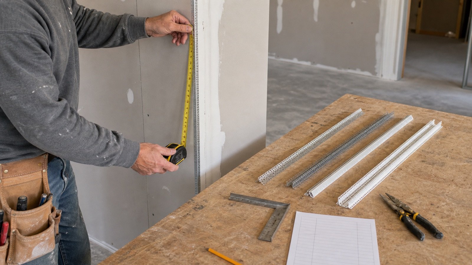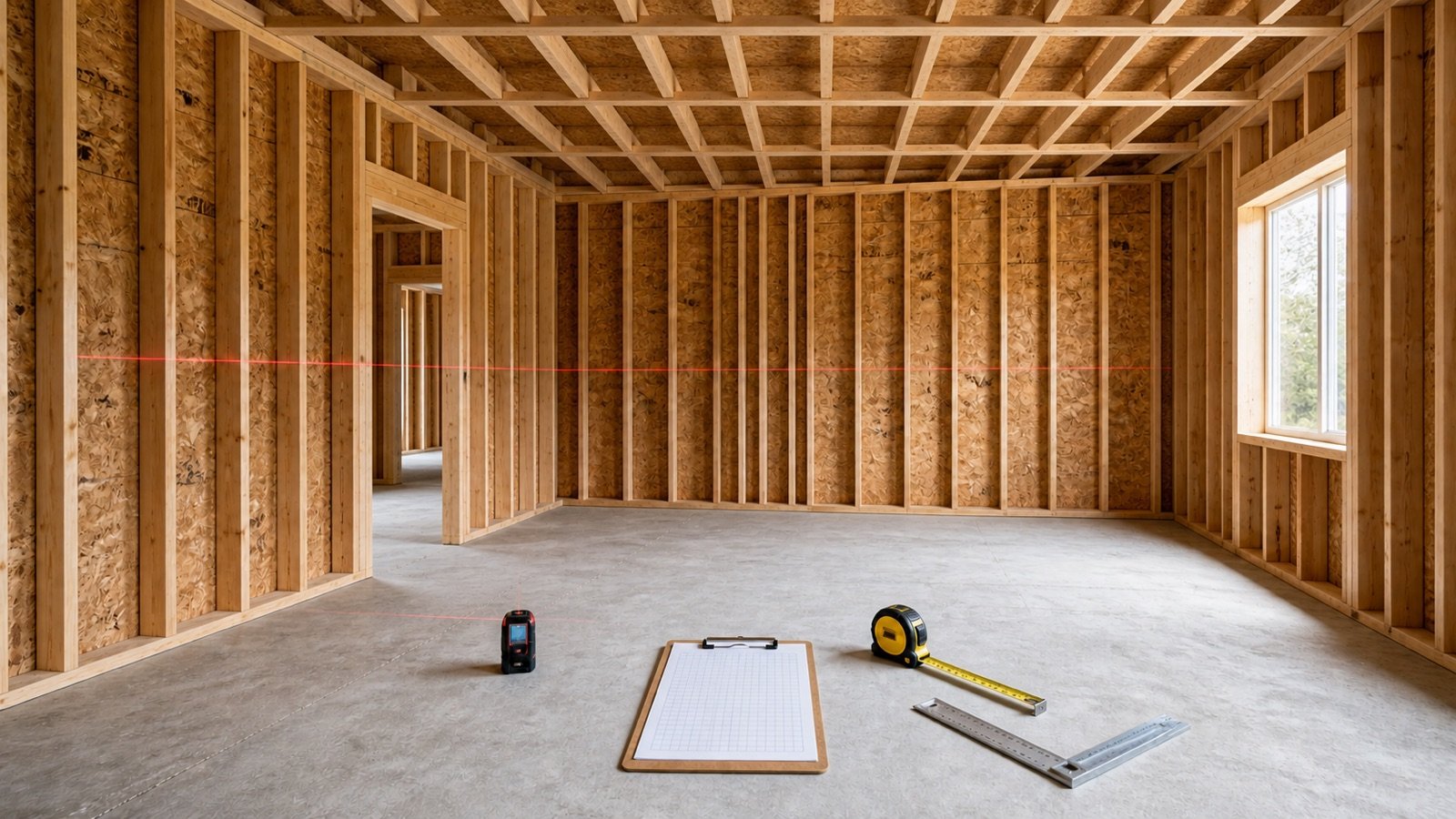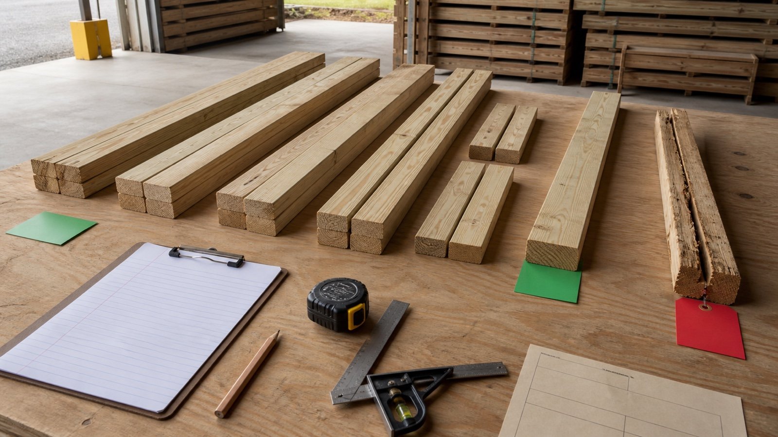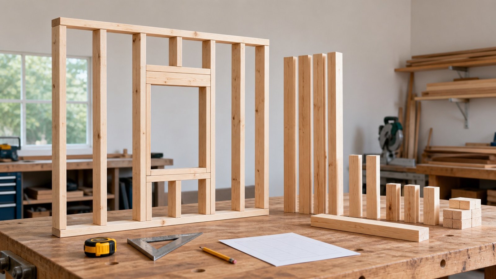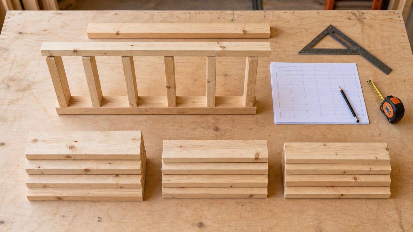
Bottom and top plates follow the same wall line, but they do not create the same takeoff row. Their position, layer count, continuity details, product requirements and stock lengths can change the quantity you order.
Separate the 2 roles before multiplying wall lengths. That small worksheet decision keeps design assumptions out of the arithmetic and makes the final order easier to check.
What is the difference between a bottom plate and a top plate?
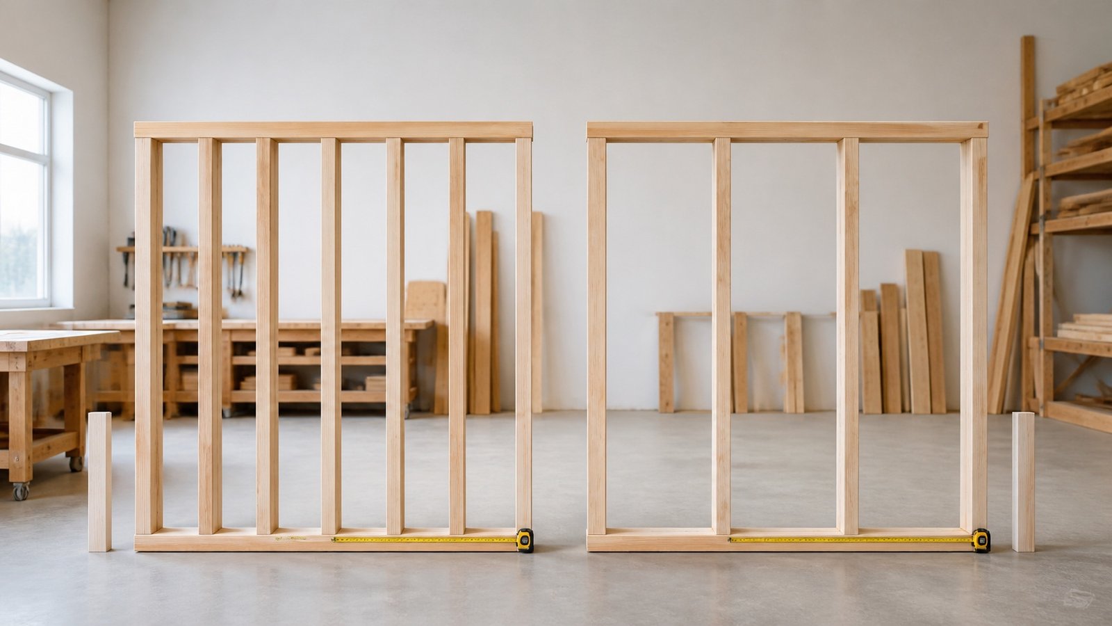
A bottom plate, also called a sole plate in many documents, forms the lower horizontal member beneath the studs. A top plate caps the studs and connects the wall to the framing or support above according to the accepted wall detail.
For a quantity takeoff, the key difference is the row definition. The bottom row starts with its approved layer count and product. The top row starts again with its own layer count, product, joint conditions and detail additions.
| Check | Bottom plate | Top plate |
|---|---|---|
| Position | Below the wall studs | Above the wall studs |
| Starting quantity | Wall run × approved bottom layers | Wall run × approved top layers |
| Common detail questions | Bearing, anchorage, moisture exposure and opening sequence | Layer count, joints, intersections, load alignment and connections |
| Opening treatment | May continue through a door during layout, depending on sequence | May continue above door and window openings, depending on detail |
| Product grouping | Separate by required size, grade, species group, seasoning, treatment and stock length | Separate by required size, grade, species group, seasoning and stock length |
| Extra-length record | Returns or project-specific additions | Laps, intersections, splice development or project-specific additions |
The 2024 IRC states that studs in its stated wall scope need support from the sole plate to the top plate. Section R602.3.4 also gives an edition-specific bottom-plate bearing requirement. Those provisions describe construction conditions; they do not supply a universal shopping multiplier.
Should you assume 1 bottom plate and 2 top plates?
No universal layer count works for every wall. Copy both layer counts from the current wall type, framing detail, specifications, accepted design and locally applicable requirements.
The 2024 IRC includes double-top-plate provisions and conditional alternatives. Its interior nonbearing-wall section permits at least a single top plate under the stated conditions. APA Form M400 covers single top plates as one part of an advanced-framing method that coordinates member alignment and connections.
A quantity worksheet should record the design decision, not make it. Changing a top row from 2 layers to 1 changes the wall system and may change load alignment, joints and connections.
Use separate rows when 2 walls follow different details, even if their measured lengths match. A bearing wall, exterior wall and interior nonbearing partition may need different records.
Why can the bottom-plate product differ from the top-plate product?
Exposure, decay-protection requirements, product specifications and connection compatibility can place the bottom plate in a different purchase group. Record the complete required identity instead of labeling both rows as 2x4 lumber.
The 2021 IRC Section R317.1 lists specific locations where naturally durable or preservative-treated wood is required in that edition. One example covers sills and sleepers on a concrete or masonry slab that contacts the ground, unless an impervious moisture barrier separates them. The rule depends on location and assembly conditions, so direct contact with any concrete surface does not support a blanket product choice.
When treated lumber is required, the same IRC chapter lists quality-mark information such as treating plant, preservative, retention, end use, treatment standard and inspection agency. It also addresses fasteners and connectors used with treated wood. Match the current project specification and product documentation before ordering.
NIST PS 20-25 supplies current American softwood-lumber terminology for nominal and dressed sizes, grades, species or species groups, seasoning and product marking. It helps describe a product but does not select a plate for a wall.
| Field | Takeoff action |
|---|---|
| Bottom or top role | Keep a separate subtotal |
| Layer count | Use a separate arithmetic row |
| Nominal or dressed size | Match the project and supplier record |
| Grade, species group or seasoning | Start a new product group when the requirement changes |
| Treatment or end use | Keep treated products separate and verify compatible fasteners and connectors |
| Stock length | Round whole pieces in a separate group |
| Unresolved requirement | Hold the row outside the order until the responsible party answers |
Do door and window openings change both plate quantities?
An opening changes a plate quantity only when the accepted detail and construction sequence omit a measured segment. Start deductions at 0, then record each approved omission against the affected row.
A crew may assemble a wall with the bottom plate running through a door opening, transfer the layout, stand and secure the wall, then cut out the door segment. That sequence still consumes the plate length. Top plates often continue above openings, but the project detail controls the actual condition.
Record the opening ID, affected row, length, drawing detail and decision owner. Keep gross length and deductions visible so a revision can reverse the decision without another wall measurement.
| Question | Required evidence |
|---|---|
| Does the bottom plate continue during layout? | Accepted installation sequence or wall detail |
| Does the top plate continue above the opening? | Current wall and opening detail |
| Which row receives a deduction? | Named bottom or top row and measured segment |
| Will removed material remain usable? | Actual cut length, condition and matching product group |
How do joints and intersections affect the top-plate takeoff?
Top-plate continuity details can add material that a wall-centreline measurement does not show. Record each measured lap, return, intersection piece or splice requirement in an extra-length ledger.
A second top layer does not mean that both layers use identical segment lengths. Joint offsets, corner laps and wall intersections can change the cut plan. Use the current detail to assign each required segment to a stock piece.
Keep detail length outside the allowance percentage. A measured lap belongs in the base requirement; an allowance covers a separate, documented planning risk.
- Name the wall, plate layer and detail reference.
- Measure the added segment once and assign it to one row.
- Check whether the base wall run already includes the return or intersection.
- Preserve the segment lengths for stock optimization.
Worked example: separate bottom and top plate rows
A straight wall measures 24 ft. The checked project detail lists 1 bottom layer and 2 top layers. The top detail also requires 4 ft of measured extra length. The example uses 12 ft stock for the bottom product, 16 ft stock for the top product, 0 deductions and 0% allowance.
Bottom-plate row
Base bottom length = 24 ft × 1 = 24 ft
Bottom pieces = ceiling(24 ft ÷ 12 ft) = 2
Top-plate row
Base top length = 24 ft × 2 = 48 ft
Net top length = 48 ft + 4 ft = 52 ft
Top pieces = ceiling(52 ft ÷ 16 ft) = 4
| Row | Required length | Stock length | Length-based pieces |
|---|---|---|---|
| Bottom product | 24 ft | 12 ft | 2 |
| Top product | 52 ft | 16 ft | 4 |
| Display total | 76 ft | 2 separate stock groups | 6 pieces |
Without the 4 ft top detail, length division would give 3 pieces of 16 ft stock. The accepted detail moves that row to 4 pieces. Enter the rows in the Wall Plate Calculator to check the arithmetic.
Why can total length still understate the piece count?
Length-based division assumes every offcut can serve another required segment. Joint locations, layer staggering, minimum segment lengths, treatment and defects can prevent that reuse.
Suppose a top layer needs 3 separate unspliced 7 ft segments. The total is 21 ft, and dividing by 12 ft stock gives 2 pieces. Each 12 ft piece supplies only one 7 ft segment, so the segment plan needs 3 pieces unless an accepted splice detail changes the requirement.
Keep the calculator result as a length-based count. Complete a segment cut plan before placing the order, then add any verified cut-plan shortage to the matching product row.
Which plate assumptions should you check before ordering?
| Assumption | Check |
|---|---|
| Every wall uses 3 plate runs | Record bottom and top layers by wall type |
| Every bottom plate needs the same treatment | Check the exact location, moisture separation, adopted requirements and specification |
| Every door width reduces the order | Check whether the plate continues during layout and is cut later |
| Both rows use the same stock length | Confirm the current supplier item for each product |
| A percentage covers laps and intersections | Measure required detail length before applying an allowance |
| Total-length division gives the final order | Assign required segments to stock pieces |
| All stored plate stock can be deducted | Verify identity, full usable length, condition and prior commitment |
How should you hand the 2 rows to purchasing?
Send one order line for each matching product and stock length. Include the source revision and preserve the arithmetic behind the rounded piece count.
- List the level, wall IDs and wall type.
- Record bottom or top role and approved layers.
- Copy the complete product identity from the accepted requirement.
- Show gross length, deductions, detail additions and allowance as separate fields.
- Attach the segment cut check and stock length.
- Record usable stock, supplier increment and final pieces to buy.
The wall-plate takeoff worksheet provides the wall-by-wall record that feeds these order lines. Keep vertical framing in the separate wall-stud takeoff worksheet.
Safety, design and code limits
This comparison supports quantity planning. It does not design the wall, choose a layer count, approve joints, verify load paths, select treatment, size members, specify anchors or fasteners, or accept substitutions.
Follow the current drawings, specifications, manufacturer instructions and locally adopted requirements. Refer a layer, joint, treatment or connection change to the designer or authority responsible for the project.
OSHA 1926.250 requires lumber stored in US construction workplaces to rest on level, solidly supported sills and remain stable and self-supporting. Apply the rules for the actual workplace, unloading method and storage area.
Return to the Drywall planning hub for related wall-framing and panel-material tools. Review the calculation methodology or report a source, formula or page issue through the corrections route.
Sources and source scope
- 2024 IRC Chapter 6: edition-specific US model-code examples for plate arrangements, sole-plate bearing and interior nonbearing walls.
- APA Advanced Framing Construction Guide, Form M400: coordinated single-top-plate framing context.
- 2021 IRC Chapter 3: edition-specific decay-protection locations and treated-product mark fields.
- NIST PS 20-25: current US softwood-lumber terminology and product-record context.
- OSHA 1926.250: US construction-workplace lumber storage requirements.
Source scope: the code pages support only their stated editions and conditions. Local adoption, amendments, drawings and specifications control project use. APA describes a coordinated framing method. NIST supports lumber terminology. OSHA supports the cited US workplace-storage rules. None of these sources approves the takeoff entries or finished wall.
Review note: Saleem Sial owns the research and editorial record. Source checks, independent arithmetic, content tests, build validation, link crawl, schema review and rendered QA form the internal publication gate. Waseem Sial, External Reviewer and Engineer, is listed for ongoing external review; no completed review date is claimed.