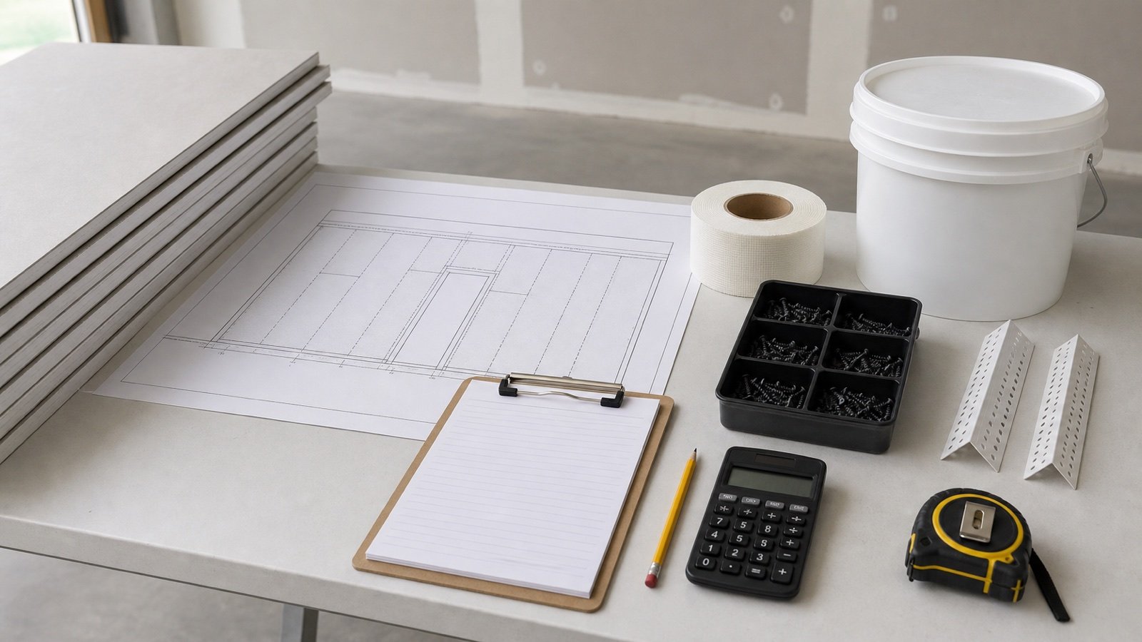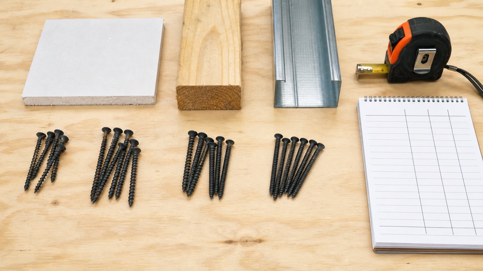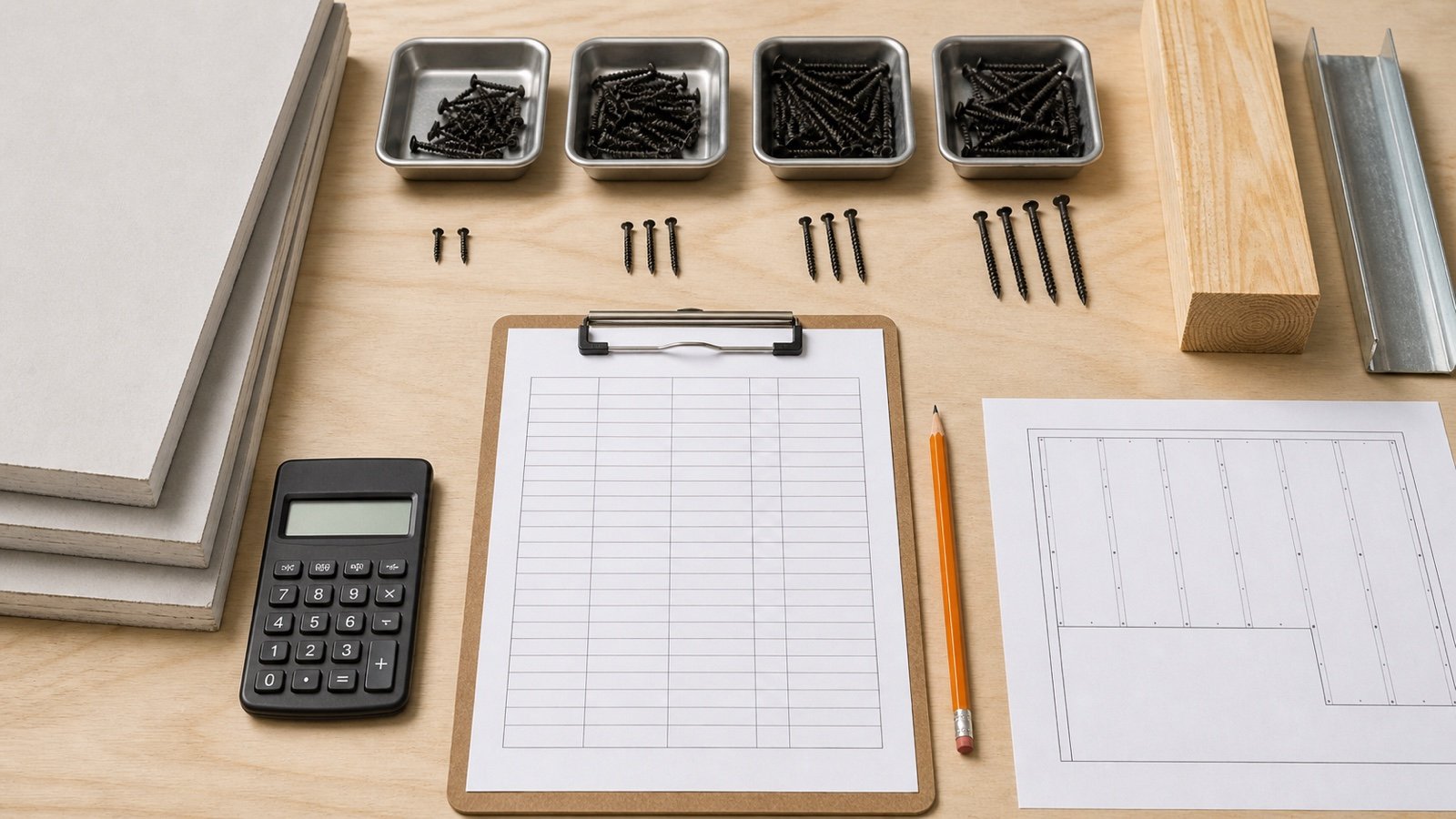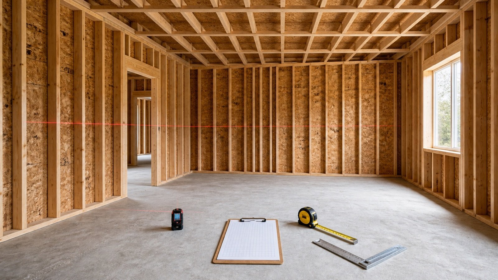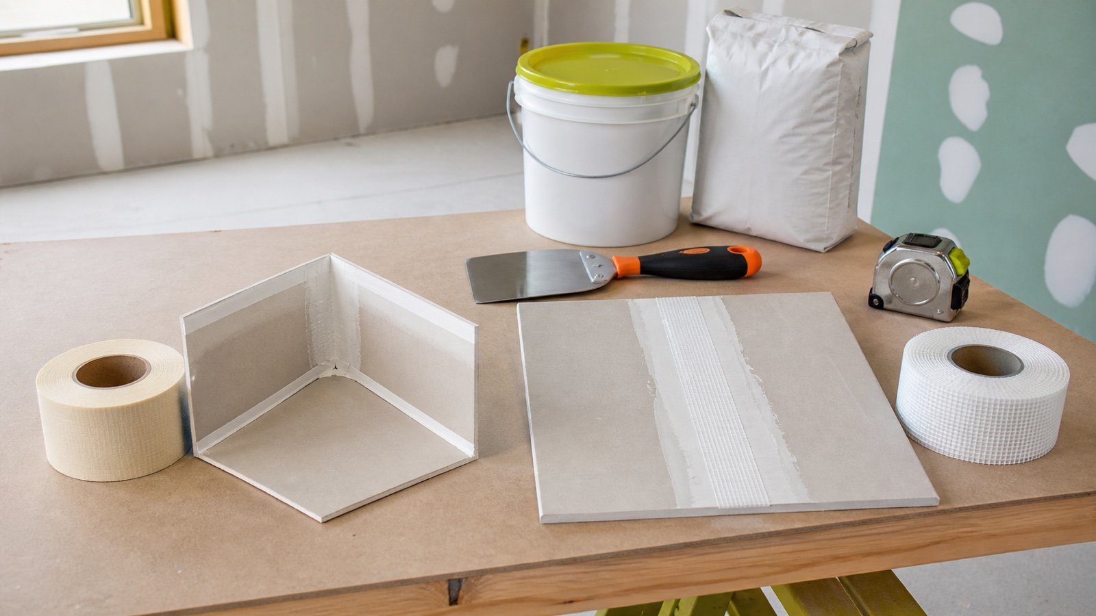
Drywall screw spacing comes from the fastening schedule for the exact wall, ceiling, panel and framing condition. A count such as 32 screws per sheet can be a useful check only after the source row and panel layout support it.
Build a separate record for each condition. Mark every support line, count the accepted fastening positions and send that reviewed whole-number total to the Drywall Screw Calculator.
What drywall screw spacing should you use on walls and ceilings?
Use the spacing in the controlling project detail, listed assembly, current panel instructions and locally adopted code. Keep the application, framing interval, panel orientation, adhesive method and layer with the spacing value.
The 2024 International Residential Code gives several examples in Table R702.3.5. For application without adhesive, the table includes 12 in maximum screw spacing for its listed ceiling condition, 12 in for a listed wall condition with framing up to 24 in on center, and 16 in for a listed wall condition with framing up to 16 in on center. A Type X garage ceiling beneath habitable rooms has a separate 6 in condition.
Those values belong to their complete rows. The same table changes requirements for adhesive applications, panel thickness, orientation and special construction. A project specification or approved method can control another pattern.
Write the document title, edition, table or assembly number and revision beside the spacing. A number copied into a worksheet without its conditions cannot support a purchase count.
Which record controls the fastening pattern?
Start with the project documents and approved assembly. Use the code and manufacturer records that apply to that construction, then resolve conflicts through the designer, code official or another qualified project professional.
| Record | Details to capture | Reason |
|---|---|---|
| Project detail | Wall type, ceiling type, detail number and drawing revision | Identifies the actual construction |
| Listed assembly | Listing, layer, panel product, framing and fastener row | Preserves tested fire or sound conditions |
| Manufacturer instructions | Panel name, thickness, orientation, framing and application method | Limits guidance to the named product |
| Adopted code | Jurisdiction, edition, section, table row and amendments | Confirms the local model-code basis |
| Approved change | RFI, substitution or written acceptance | Records who accepted a different method |
The 2024 IRC page now labels its January 2024 text as a historical version. That page remains a source for the stated edition, while a current project must check its adopted edition and amendments.
Which conditions must stay on separate rows?
Separate any condition that changes the source document, spacing, support layout, screw specification or installation method. Combining unlike rows removes the evidence behind the total.
- Walls and ceilings.
- Wood and cold-formed steel framing.
- Different framing intervals or furring layouts.
- Base and face layers in multilayer work.
- Adhesive-assisted and screw-only applications.
- Rated assemblies and ordinary partitions.
- Garage ceilings, diaphragms, braced walls and proprietary systems.
- Full sheets, partial sheets, openings, patches and soffits.
National Gypsum's current Working Properties FAQ gives a specific example. Its MaX 16 pattern cannot be used on ceilings because the ceiling pattern changes with member spacing and materials. The same FAQ limits the named patterns to Gold Bond products and their specified UL assemblies.
How do you turn spacing into a screw count?
Draw the panel and its supports, mark the accepted fastening positions, then count the marks. A formula works for a regular exact-multiple layout, though the drawing remains the check.
- Name one condition. Record wall or ceiling, panel, thickness, orientation, layer, framing and application method.
- Cite the controlling row. Record the document, edition, table or assembly and revision.
- Draw support lines. Mark the supports that receive fasteners under the accepted layout.
- Mark positions on each line. Use the accepted maximum interval and the required endpoint treatment.
- Count the repeated panel. Keep the count as a whole number.
- Add exceptions separately. Count partial sheets, openings and special details from their drawings.
- Review shared edges. Define which panel or elevation row owns each installed fastener so the takeoff does not count it twice.
For an exact-multiple rectangular layout where both endpoints receive fasteners, use these planning checks:
Support lines = panel dimension crossing supports ÷ support interval + 1
Positions per support line = panel dimension along support ÷ fastener interval + 1
Repeated-panel count = support lines × positions per support line
Draw the positions when either division leaves a remainder. Rounding a ratio without checking the endpoints can place a mathematical position outside the panel or miss a required position near an edge.
Worked example: 4 ft by 8 ft wall panel on 16 in supports
A reviewed wall condition uses a 96 in panel dimension across supports at 16 in on center. Its 48 in dimension runs along each support, and the accepted schedule places fasteners at a maximum 16 in interval. Both endpoints receive positions in this declared layout.
- Support spaces: 96 ÷ 16 = 6.
- Support lines: 6 + 1 = 7.
- Fastener spaces on each line: 48 ÷ 16 = 3.
- Positions on each line: 3 + 1 = 4.
- Repeated-panel count: 7 × 4 = 28 screws.
The 28-screw result belongs to this declared geometry and schedule. It does not set the count for another wall, a ceiling, a different orientation, an adhesive method or a listed assembly.
If a reviewed detail adds 6 positions around a partial panel or opening, keep the arithmetic visible: 28 + 6 = 34. Enter 34 as the direct count, or keep 28 as the approved repeated-panel count and enter the 6 detail screws separately.
Worked example: the same panel size with a different framing row
A second declared wall condition has supports at 24 in on center across the 96 in panel dimension. Its accepted screw interval is 12 in along the 48 in support line. Both endpoints receive positions.
- Support lines: 96 ÷ 24 + 1 = 5.
- Positions per line: 48 ÷ 12 + 1 = 5.
- Repeated-panel count: 5 × 5 = 25 screws.
The panel area stays at 32 ft², while the support and fastening grid changes. An area-only rate cannot reproduce both declared patterns.
How should partial sheets and openings be counted?
Count their actual support lines and accepted positions from the elevation. A partial panel rarely preserves the full-sheet grid, and an opening can add backing or detail fasteners that an area deduction cannot see.
| Condition | Count from | Avoid |
|---|---|---|
| Narrow rip | Actual supports and endpoints | Prorating a full-sheet count by area |
| Door or window cut | Accepted backing and opening detail | Subtracting opening area from screws |
| Patch | Repair detail and installed backing | Applying the room's full-sheet rate |
| Soffit or return | Each face, support and corner detail | Combining all faces into one area rate |
| Shared support | Installed positions assigned once in the ledger | Counting the same fastener in both panel rows |
| Multilayer work | Layer-specific assembly schedule | Multiplying one layer's count by the number of layers |
The drywall measurement guide creates the surface ledger. The Drywall Calculator checks sheet area and rectangular layouts, though it does not select or draw a fastening pattern.
Which common screw-spacing shortcuts can fail?
| Shortcut | Required check |
|---|---|
| 32 screws per 4 ft by 8 ft sheet | Panel orientation, framing interval, spacing row, endpoints and exceptions |
| 1 screw per square foot | Support-line geometry and separate wall or ceiling condition |
| 16 in on walls and 12 in on ceilings | Full manufacturer, code-table or assembly conditions |
| More screws make every assembly safer | Accepted schedule, edge distance, screw setting and panel condition |
| Printed guide marks approve the pattern | Product, listed assembly and permitted application behind the marks |
| Adhesive reduces screws on every project | Approved adhesive method and its complete mechanical-fastener schedule |
| One count covers wood and steel | Screw type, framing thickness, penetration and accepted schedule |
USG J371 gives 12 in maximum spacing on ceilings, 16 in on walls and at least 3/8 in from panel ends and edges for its stated guide context. The 2024 IRC contains other rows. Keep the USG guidance with the named product and application instead of turning it into a universal edge-and-field chart.
How do you move the reviewed count into a purchase order?
Use the Drywall Screw Calculator after the schedule ledger has a whole-number count. Choose per-panel mode for repeated panels under one reviewed condition, or direct-count mode for detailed elevations and mixed partial sheets.
- Run one calculator record for each screw specification and condition.
- Enter the approved panel count or direct count.
- Add separately counted detail screws.
- Apply only a documented allowance.
- Deduct verified usable matching stock.
- Use the count printed on the current box and round to whole boxes.
The drywall material takeoff worksheet keeps the source row, screw specification, base count, allowance, stock and package record together.
What should you verify before installation or ordering?
- The project detail and drawing revision match the location.
- The adopted code edition and local amendments are current.
- The panel product, thickness, orientation and layer match the source row.
- The framing material, thickness and spacing match the layout.
- The screw type, size and penetration meet the accepted requirement.
- Adhesive, rated and special construction use their own schedules.
- Partial sheets, openings and shared edges have visible count ownership.
- The calculator row contains one screw specification and one current package count.
Quantity planning does not approve an assembly or installation. Follow current drawings, listed assemblies, manufacturer instructions, local requirements and site safety controls. Ask the responsible designer, code official or qualified project professional to resolve a missing or conflicting schedule.
Return to the Drywall planning hub for sheet, tape, compound and fastener tools. The calculation methodology explains fixture and rounding checks. Report a source or arithmetic issue through the corrections route.
Sources and source scope
- 2024 International Residential Code, Section R702.3.5 and Table R702.3.5 supports the stated US model-code rows for application, orientation, framing and maximum fastener spacing. Section R702.3.5.1 supports the named wood and cold-formed steel screw requirements.
- USG Sheetrock Installation and Finishing Guide J371 supports the named USG wall, ceiling and panel-edge spacing guidance.
- National Gypsum Working Properties FAQ supports the product and assembly limits of the MaX patterns and the statement that ceilings require a different pattern based on member spacing and materials.
Source scope: the IRC is a model code, and the retrieved page identifies the January 2024 version as historical. USG and National Gypsum control only their named products and conditions. These sources do not approve either worked example for a real project, set a universal screws-per-sheet value, choose an allowance or confirm a supplier's current package count.
Review note: Saleem Sial owns the research and editorial record. Source checks, independent fixtures, editorial review, build validation, link crawl, schema review and rendered QA form the internal publication gate. Waseem Sial, External Reviewer and Engineer, is listed for ongoing external review; no completed review date is claimed.