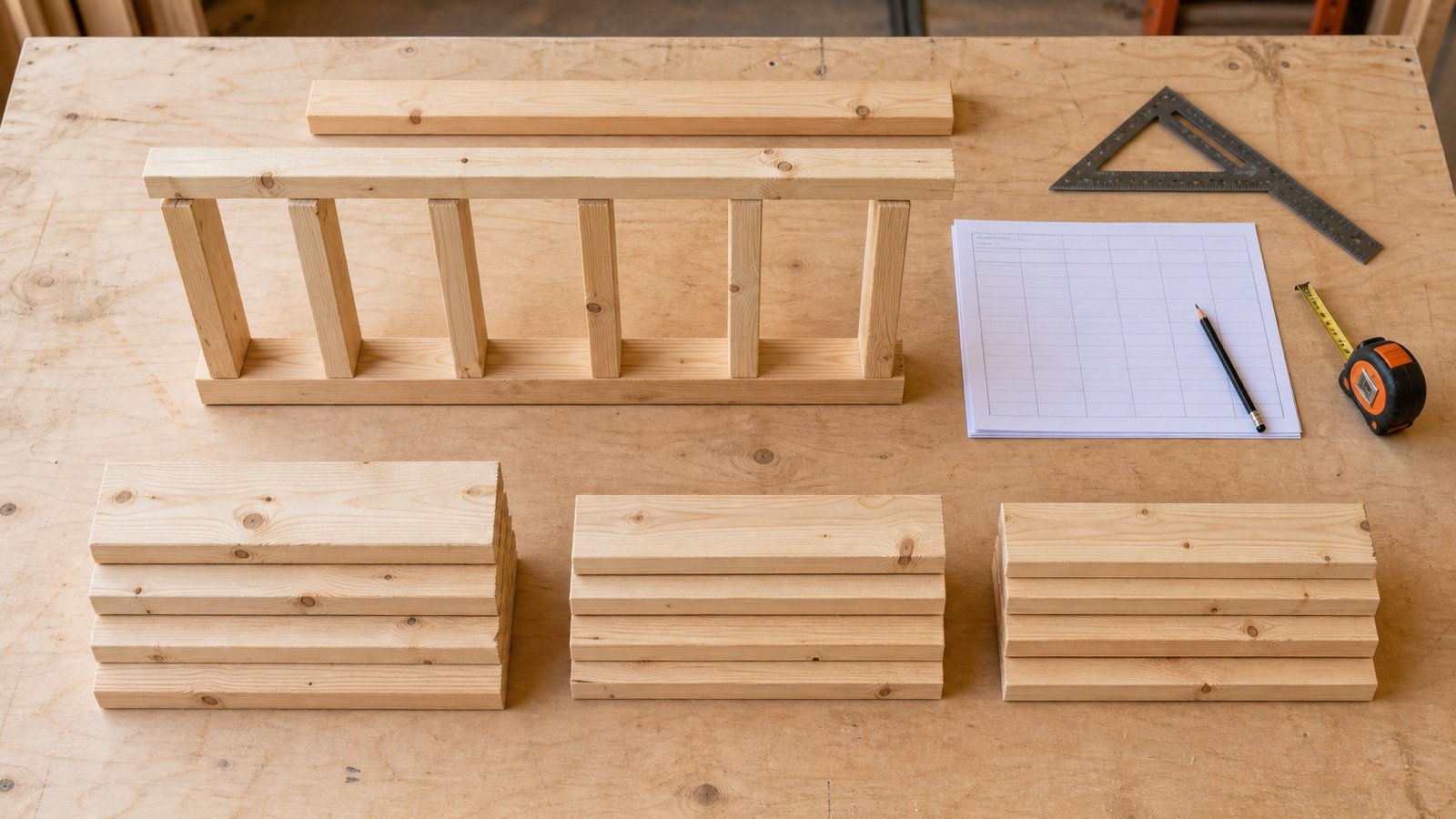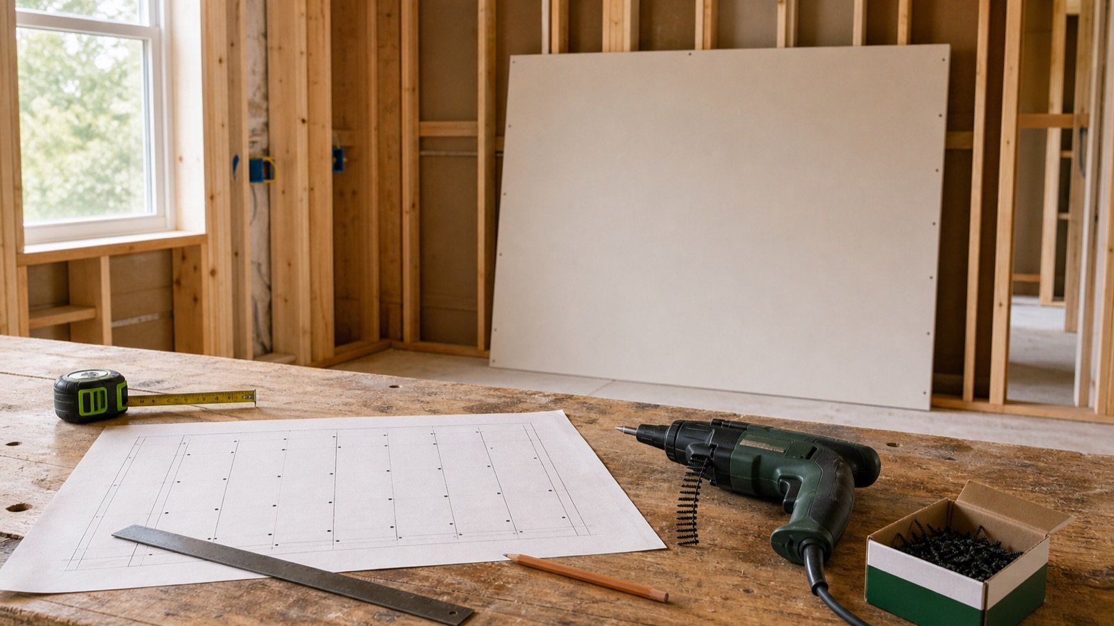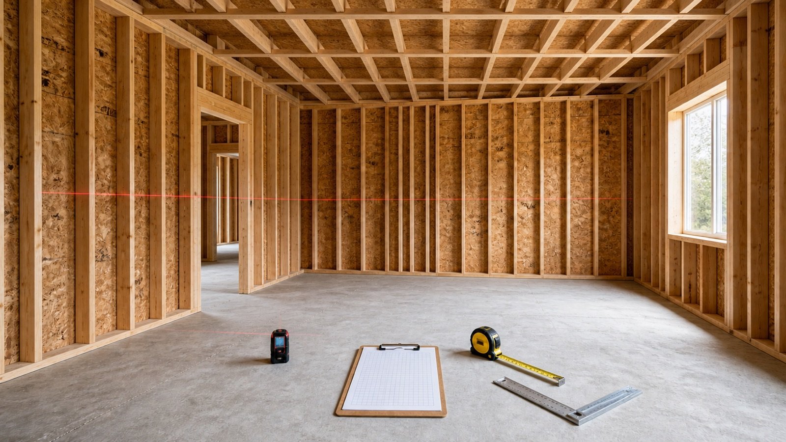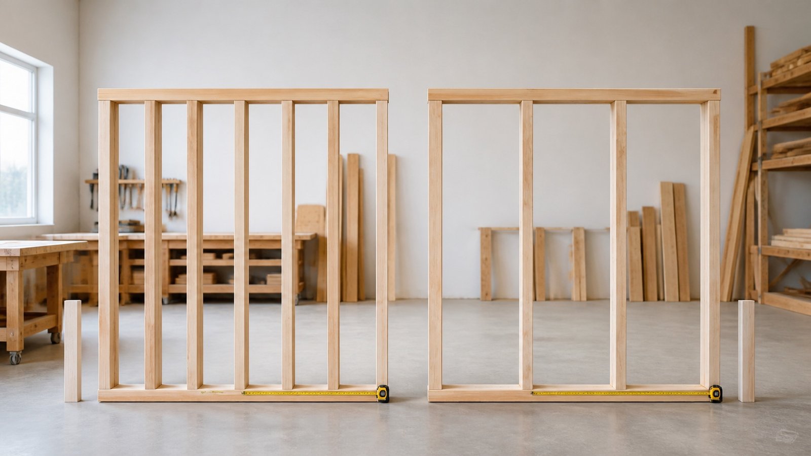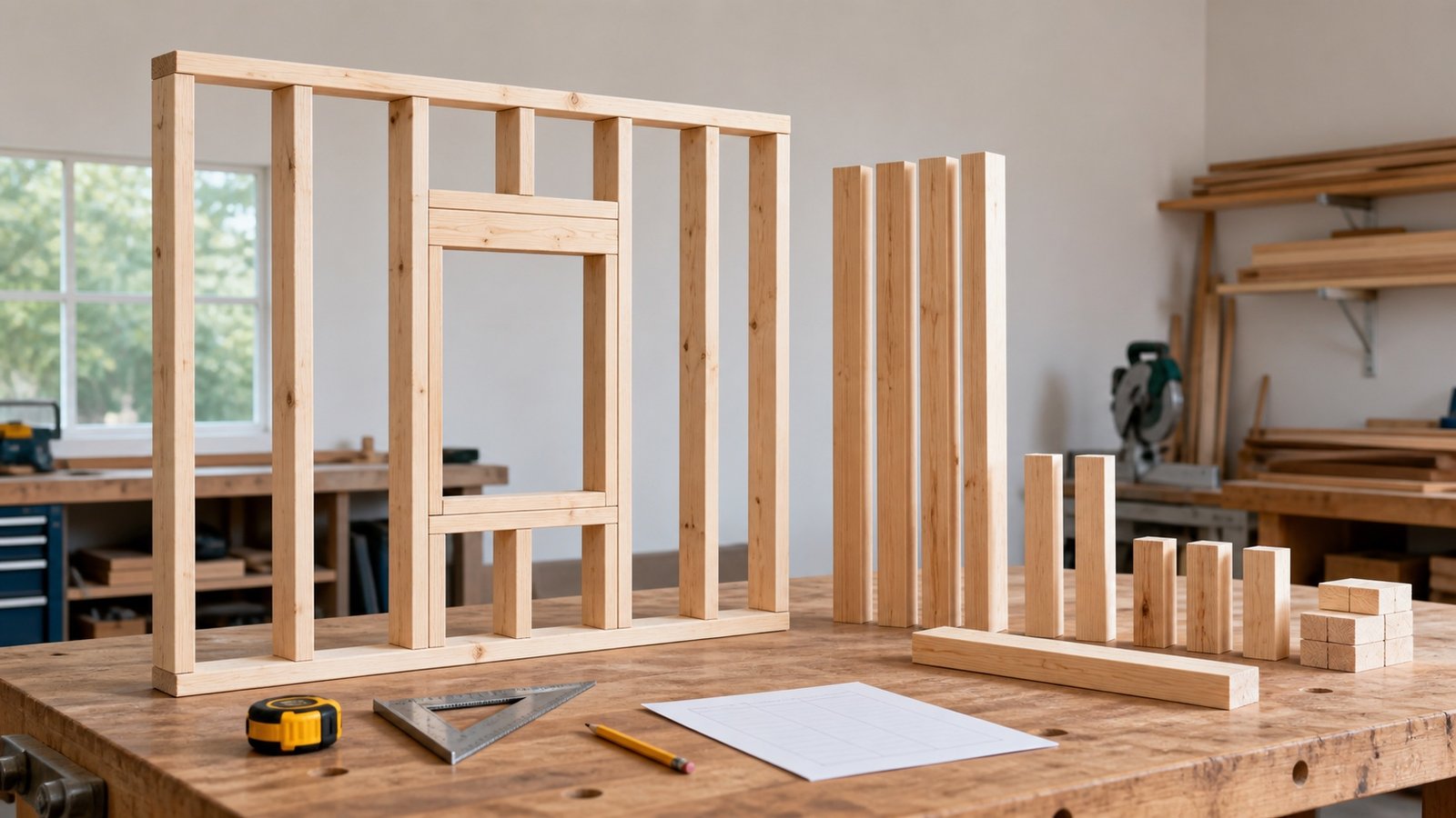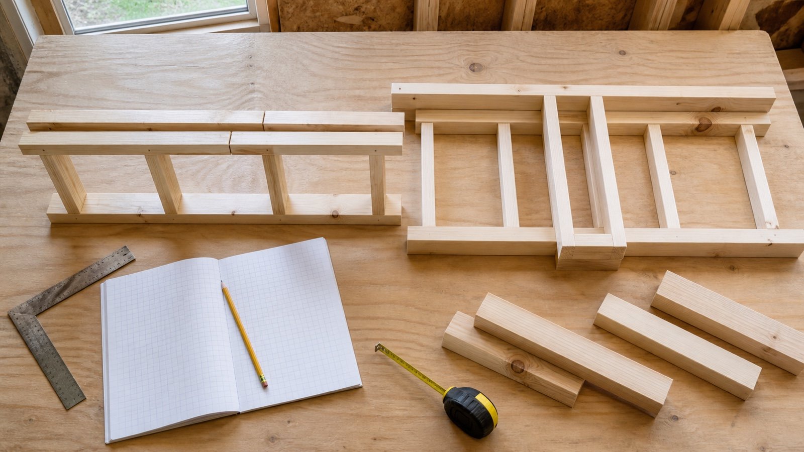
Wall-plate splices, laps and intersections can change the lumber order, but the drawing must show which detail creates extra material. A joint-location note alone does not supply a purchase length.
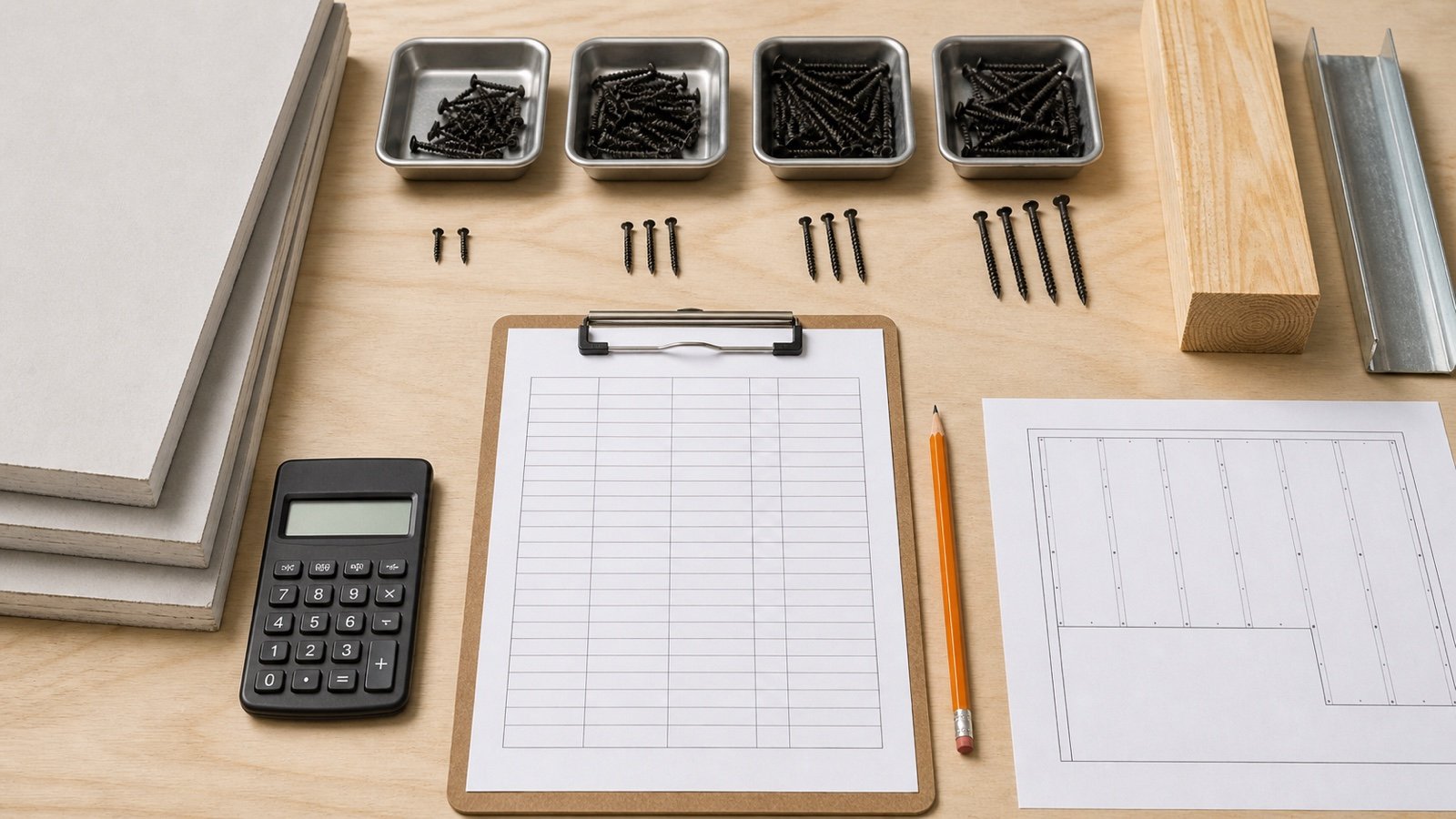
Build the takeoff layer by layer. Keep the measured wall run, detail additions, connectors and required cut segments in separate fields so the reviewer can trace every piece.
How should wall-plate splices, laps and intersections be measured?
Start with each wall's measured base run and approved plate layers. Add a separate length only when the accepted detail requires a lumber segment outside those base runs, then assign that segment to one wall, one layer and one product row.
A splice joins plate segments along a wall line. A lap describes a physical overlap or continuation shown by the detail. An intersection occurs where wall lines meet. The same location can involve all 3 concepts, but each creates a different takeoff question.
| Detail term | What it describes | Takeoff action |
|---|---|---|
| End joint | Point where 2 plate pieces meet along one layer | Record the joint location and required segments |
| Joint offset | Distance between joint locations in adjacent layers | Check segment layout; add no length from the offset value alone |
| Lap or overlap | Physical continuation required by an accepted detail | Measure any portion outside the base run and assign it once |
| Corner | Meeting of wall lines at a change in direction | Check which layer continues and whether both wall runs already include it |
| T-intersection | One wall terminates at another wall | Assign any required connection segment to a named host row |
| Connector or scab | Separate item used by the accepted connection detail | Keep its identity and count outside plate-lumber length |
Does a joint offset add the same length as a lap?
A joint offset controls the relative positions of 2 joints. It does not state that the wall needs that distance as extra lumber.
The 2024 International Residential Code Section R602.3.2 includes an edition-specific minimum offset for end joints in top plates within its stated scope. The same section addresses overlapping at corners and intersections with bearing partitions. Treat those as construction conditions, then measure the accepted project detail. Do not convert the offset value into a universal lap allowance.
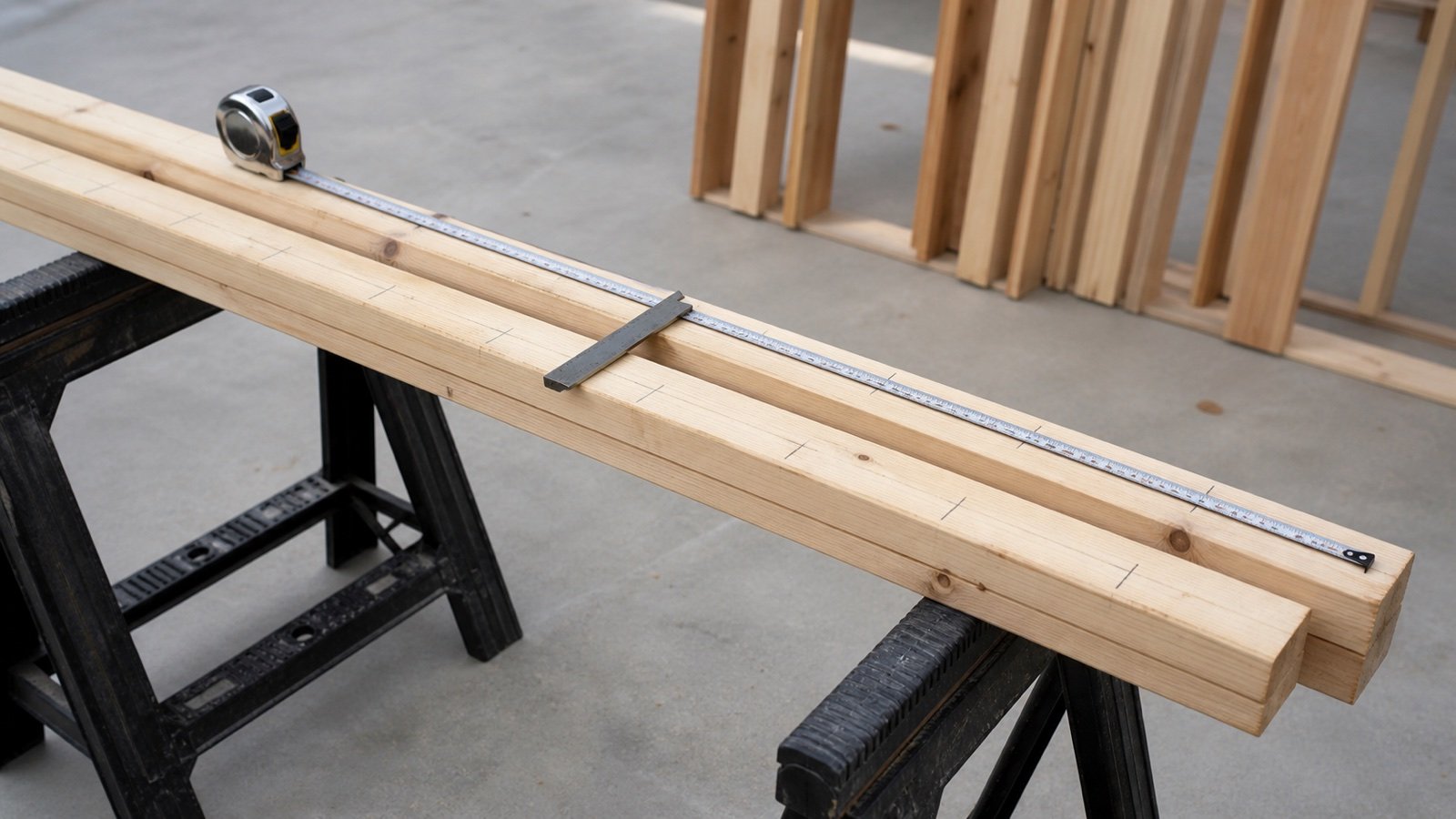
Write the joint station under location. Write a measured return, overlap or added segment under detail addition. A reviewer can then see why the order changed.
A 24 in joint offset, for example, can be achieved by selecting different segment lengths within the same total wall run. The wall still has the same base length. Extra quantity enters the ledger when a physical piece extends beyond that measured run or the detail adds a separate lumber component.
Which plate layer receives the detail addition?
The drawing decides which layer receives the added segment. Name the layer instead of placing one combined value against the wall.
| Row | Record | Reason for separation |
|---|---|---|
| Bottom plate | Base run, approved deductions, returns and its own stock length | Product, exposure and construction sequence can differ from top plates |
| First top layer | Base run and its joint stations | Its segment boundaries can differ from the upper layer |
| Upper top layer | Base run, joint stations and approved corner or intersection continuations | It may provide continuity through a detail that changes the cut plan |
| Separate scab or lumber tie | Exact size, length, count and detail reference | It is a distinct component rather than a plate-layer multiplier |
| Metal connector | Specified product or performance requirement and count | Connector counts cannot be hidden inside lumber allowance |
The layer names in the worksheet should match the drawing legend. Use first top layer and upper top layer when lower and upper could be confused with the bottom plate.
APA's DT-AF-7 longitudinal top-plate detail shows that a single-top-plate splice can use different accepted connection arrangements. APA DT-AF-4 shows corner and T-junction options for a single-top-plate advanced-framing context. Those details demonstrate why a takeoff must cite the selected connection; they do not authorize a substitute for the project design.
When does a corner or wall intersection add plate length?
An intersection adds plate length when the accepted detail requires material that the measured base runs do not contain. Give it no automatic multiplier.
Suppose the estimator measured both wall centrelines through a corner. Adding each measured wall run already captures the base geometry. Adding the corner dimension again would count the same length twice unless a named plate layer continues, returns or overlaps outside those runs.
| Check | If yes | If no |
|---|---|---|
| Do the base wall runs already include the meeting point? | Do not add the shared geometry again | Complete or correct the base measurement first |
| Does the accepted detail show a layer extending past its base run? | Measure the extension and assign it to that layer | Leave the detail-addition field at 0 |
| Does the detail require a separate lumber scab or tie? | Create a separate product and segment row | Keep the plate-lumber row unchanged |
| Does the connection use a specified metal item? | Create a connector count linked to the detail | Do not invent a connector allowance |
How do you prevent double counting at a T-intersection?
Choose one host wall for every added intersection segment. The terminating wall may supply the reference, but only one purchase row receives the length.
Use an intersection ID such as I-03. Record the host wall, terminating wall, affected layer, detail number, measured addition and product identity. Add a short note when the base run already contains part of the segment.
- Mark the intersection once on the plan takeoff.
- Assign one host wall and one layer.
- Measure only the portion outside the base runs.
- Keep connector quantities in a separate line.
- Cross out the open item after the responsible reviewer accepts the entry.
A host-wall rule also makes revisions safer. Moving a partition changes one intersection record instead of 2 wall totals with hidden allowances.
Worked example: base length plus measured detail additions
A wall run measures 22 ft. The checked wall detail lists 2 top-plate layers. The detail ledger contains 6 ft of measured additions assigned to the upper top layer, with 0 deductions and 0% allowance. The matching supplier item comes in 16 ft stock.
Base top-plate length = 22 ft × 2 = 44 ft
Net required length = 44 ft + 6 ft = 50 ft
Length-based pieces = ceiling(50 ft ÷ 16 ft) = 4
| Field | Value | Evidence |
|---|---|---|
| Wall run | 22 ft | Checked plan measurement |
| Top layers | 2 | Accepted wall type |
| Detail additions | 6 ft | Named splice and intersection ledger entries |
| Stock length | 16 ft | Matching supplier item |
| Length-based result | 4 pieces | Rounded after the product subtotal |
Leaving out the 6 ft detail record gives 3 pieces because ceiling(44 ÷ 16) equals 3. The measured detail moves the row to 4 pieces. Check the same inputs in the Wall Plate Calculator.
The example tests arithmetic. Its 6 ft addition does not prescribe a splice length, lap or intersection detail for a real wall.
Why can the segment plan require more pieces than total length?
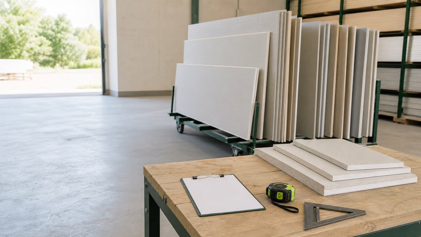
Total-length division assumes that every offcut can supply another required segment. Minimum unspliced segment lengths and fixed joint locations can block that reuse.
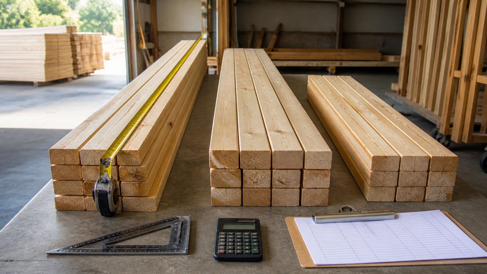
Four required unspliced segments of 9 ft total 36 ft. Dividing by 16 ft stock and rounding up gives 3 pieces. One 16 ft piece cannot supply 2 segments of 9 ft, so the segment assignment needs 4 pieces unless an accepted alternate joint detail changes the requirements.
| Check | Calculation | Pieces |
|---|---|---|
| Length-based lower bound | ceiling(36 ft ÷ 16 ft) | 3 |
| Segment assignment | 4 separate 9 ft segments; one per stock piece | 4 |
| Order basis | Use the higher checked requirement | 4 |
Preserve the required segment list after using the calculator. The calculator returns a length-based piece count; it does not place joint stations on stock boards.
Can longer stock remove a splice?
A longer matching stock item can change the cut plan when the drawings, specifications, supplier item and handling plan permit it. Confirm the substitution before changing the count.
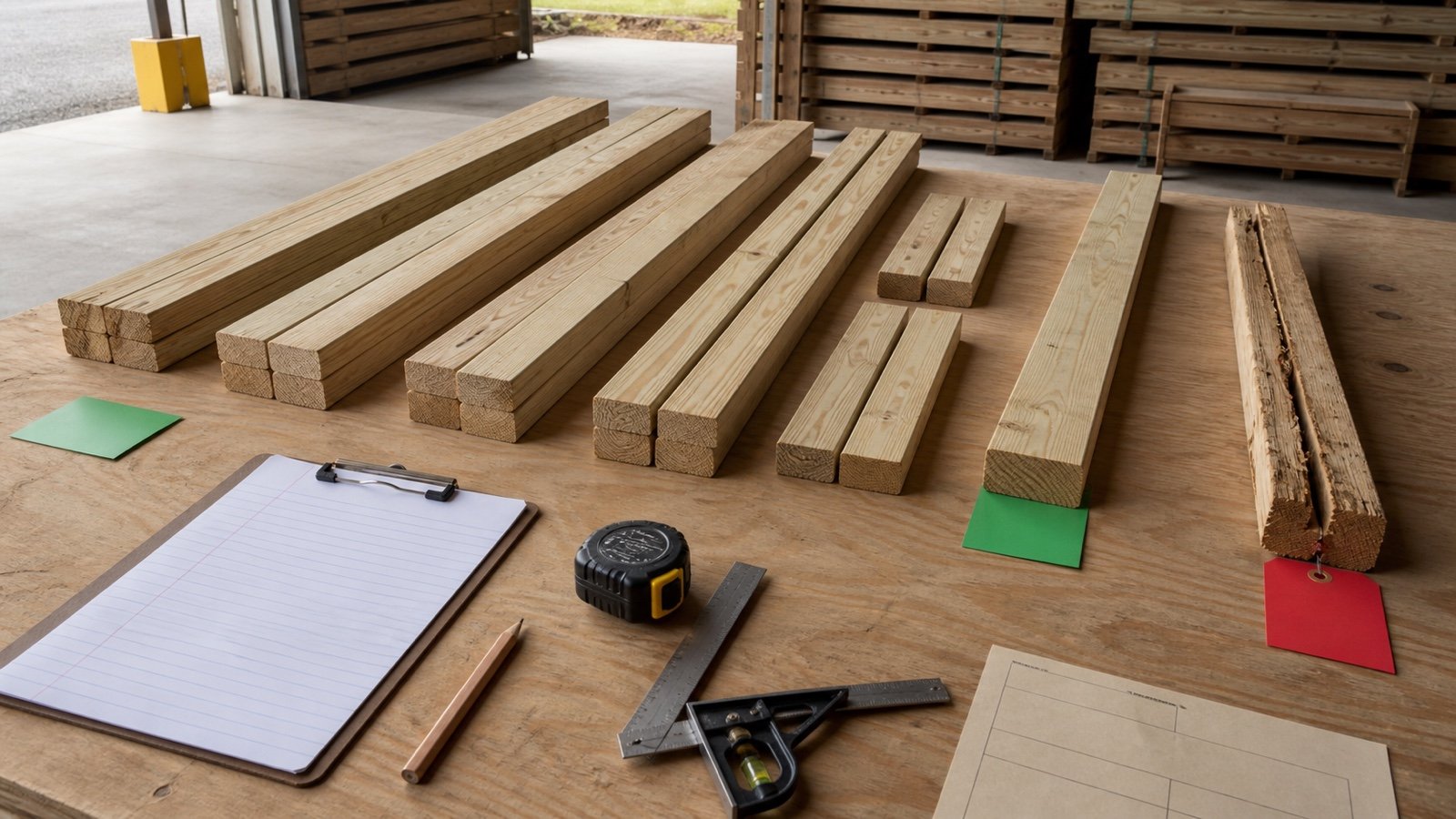
Check size, grade, species group, seasoning, treatment, stock length and any product-specific mark. NIST PS 20-25 defines current US softwood-lumber terminology for those product records, but it does not select a member or approve a substitute.
Longer stock can also change delivery access, unloading and storage. A mathematical reduction in joints does not prove that the boards can reach the work area or remain usable.
Which wall-plate assumptions should the reviewer reject?
| Unverified entry | Required check |
|---|---|
| Use the joint-offset distance as added lumber | Measure physical material outside the base run |
| Add one lap at every corner | Read the affected layer and accepted corner detail |
| Add the same intersection length to both walls | Assign one host wall and remove shared geometry |
| Use one connection for single and double top plates | Match the wall system and selected detail |
| Put connectors inside a lumber percentage | Create a named connector row and count |
| Use total-length division as the final order | Test the required segment list against stock lengths |
| Replace specified stock with a longer board | Confirm product identity, design acceptance, access and supplier availability |
How should a splice and intersection ledger be built?
Give every open detail one row. A compact ledger keeps measurement, design acceptance and purchasing status visible without mixing their owners.
- Record the plan revision, level, wall ID and intersection ID.
- Name the plate layer and complete lumber product identity.
- Reference the accepted detail and mark the joint stations.
- Measure each addition outside the base run.
- List required segment lengths and matching stock length.
- Record the length-based count, segment-checked count and final pieces to buy.
- Keep unresolved detail changes outside the issued order.
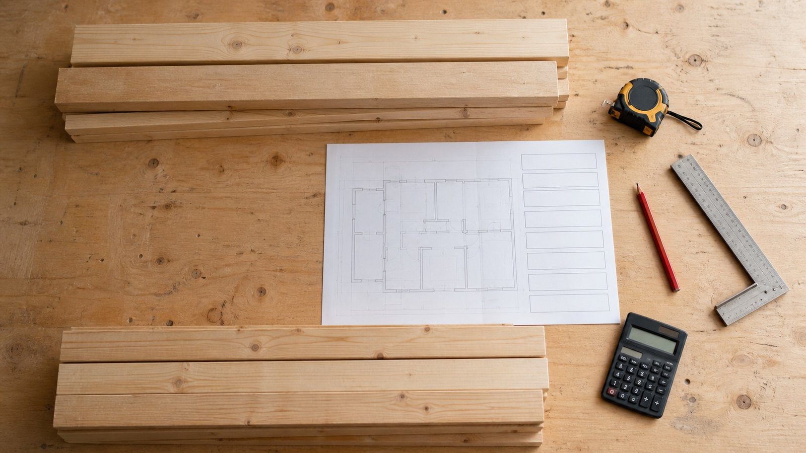
The wall-plate takeoff worksheet provides the wall-by-wall base record. The bottom plate versus top plate guide helps separate layer, product and opening decisions before you add splice data.
How should revisions and field changes be handled?
Keep the earlier quantity, change reason and current accepted detail in the ledger. Recalculate only the affected wall, layer and product group.
A field proposal to move a joint, shorten an overlap, add a connector or replace a product needs approval from the person responsible for the work. Quantity software can show the purchase effect after that decision; it cannot accept the connection.
Mark salvaged pieces as usable only after checking their full length, product identity, damage, treatment, prior cuts and commitment to another wall. A loose offcut is not an automatic deduction.
Safety, design and code limits
This guide supports quantity planning. It does not design a wall, select a splice or connector, approve joint locations, specify fasteners, verify load paths or replace structural drawings and local requirements.
Use the code edition adopted for the project, its amendments, the current drawings, specifications and accepted details. Send connection changes to the designer or authority responsible for approval.
OSHA 1926.250 requires lumber stored in covered US construction workplaces to rest on level, solidly supported sills and remain stable and self-supporting. Plan storage and handling for the actual stock length and site conditions.
Return to the Drywall planning hub for related wall-framing and panel tools. Review the calculation methodology or report a source, formula or page issue through the corrections route.
Sources and source scope
- 2024 IRC Chapter 6: edition-specific model-code examples for top-plate overlap, joint offset and single-top-plate conditions.
- APA DT-AF-4, Intersecting Wall Connection: single-top-plate T-junction and corner connection options in an advanced-framing context.
- APA DT-AF-7, Longitudinal Top Plate Splice: project-detail context for longitudinal single-top-plate splice arrangements.
- NIST PS 20-25: current US softwood-lumber terminology and product-record context.
- OSHA 1926.250: US construction-workplace lumber storage requirements.
Source scope: the code page supports only its stated edition and conditions. Local adoption, amendments and project documents control. APA provides typical details for defined applications. NIST supports lumber terminology. OSHA supports the cited workplace-storage rule. None of these sources approves the takeoff entries or finished connection.
Review note: Saleem Sial owns the research and editorial record. Source checks, independent arithmetic, content tests, build validation, link crawl, schema review and rendered QA form the internal publication gate. Waseem Sial, External Reviewer and Engineer, is listed for ongoing external review; no completed review date is claimed.