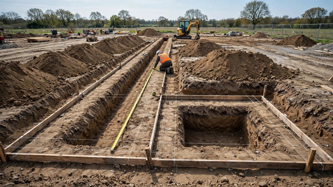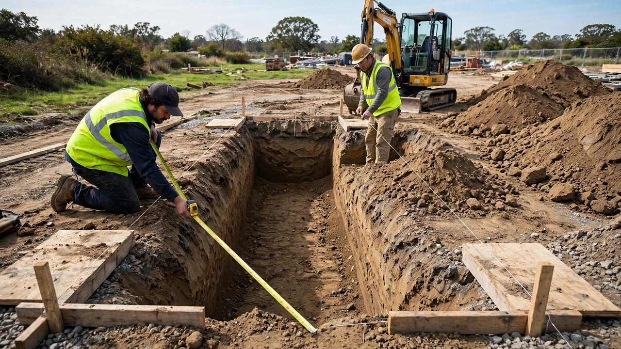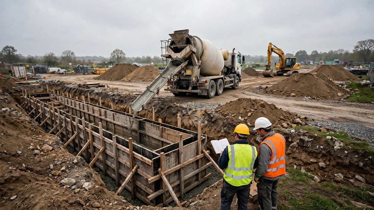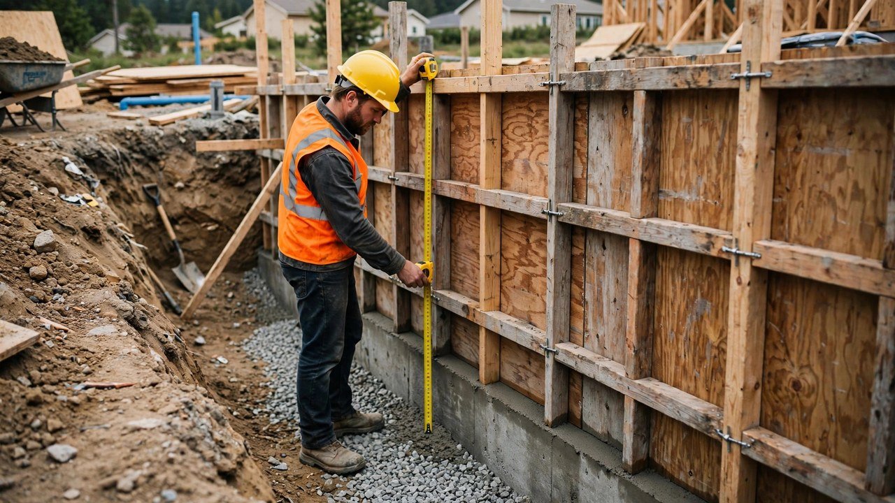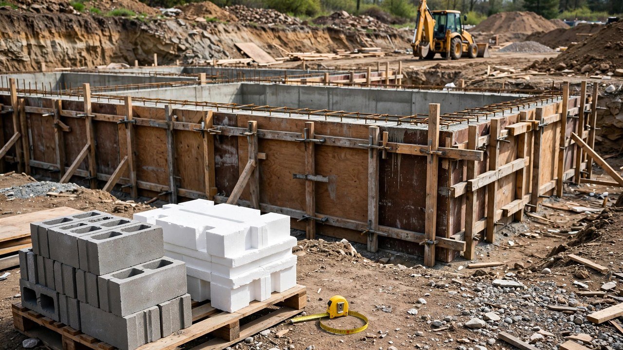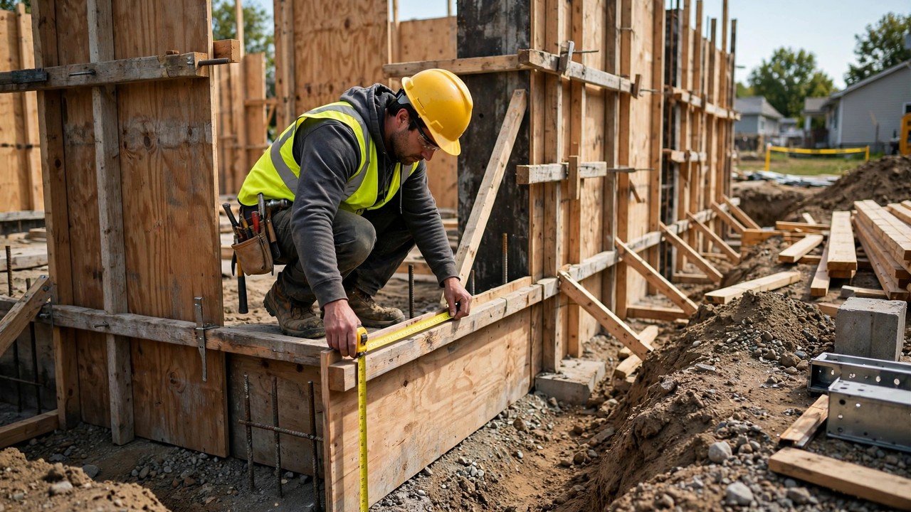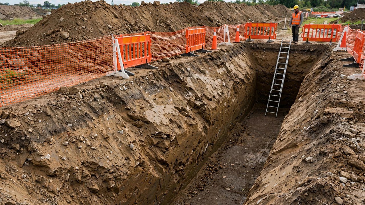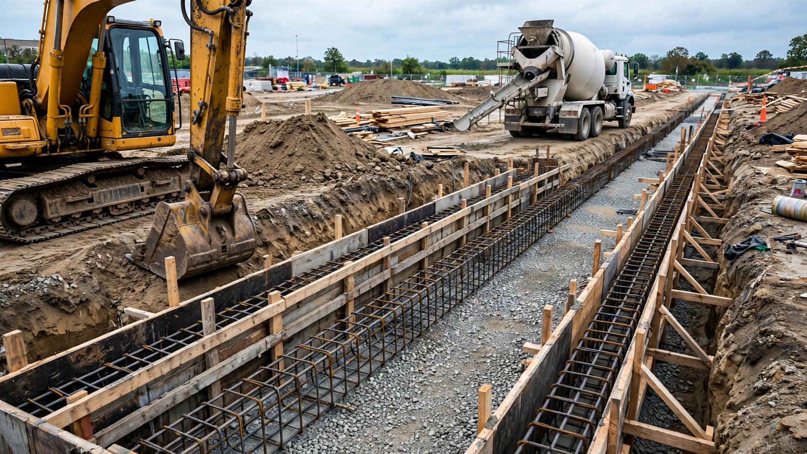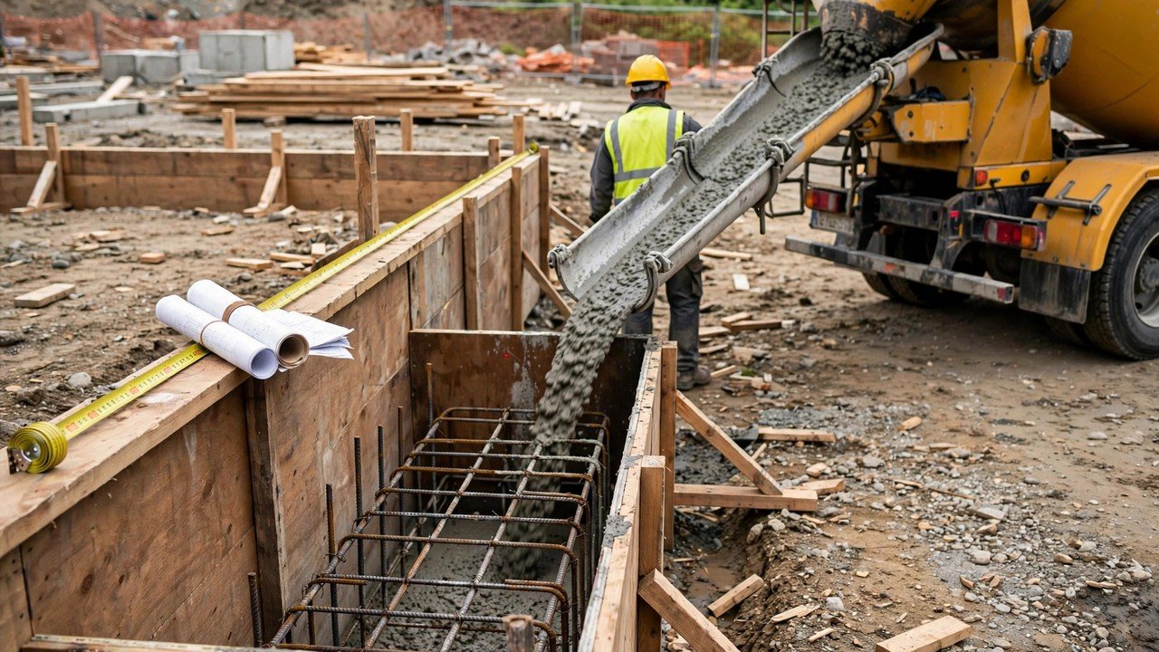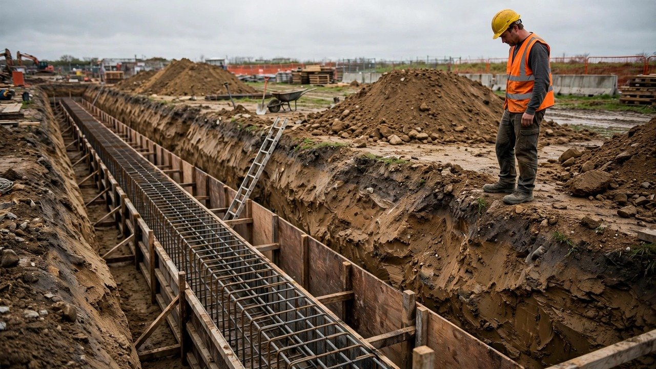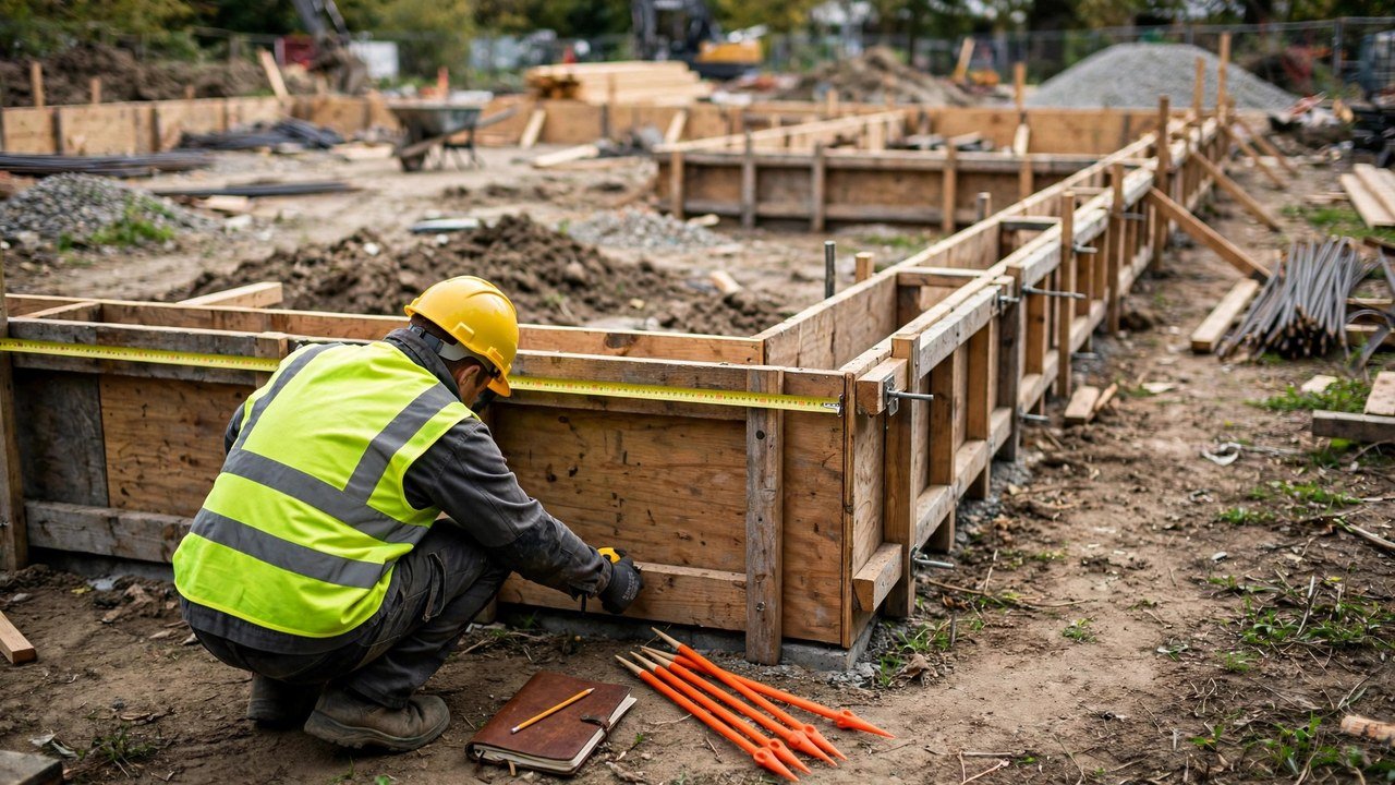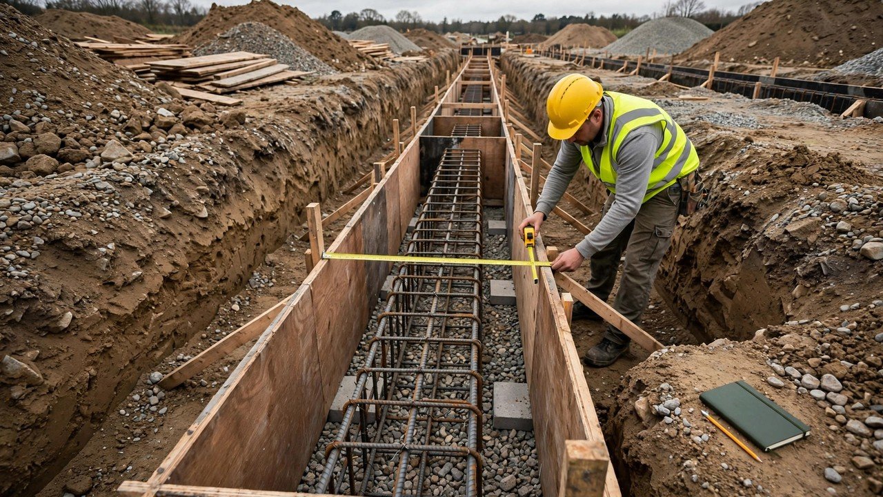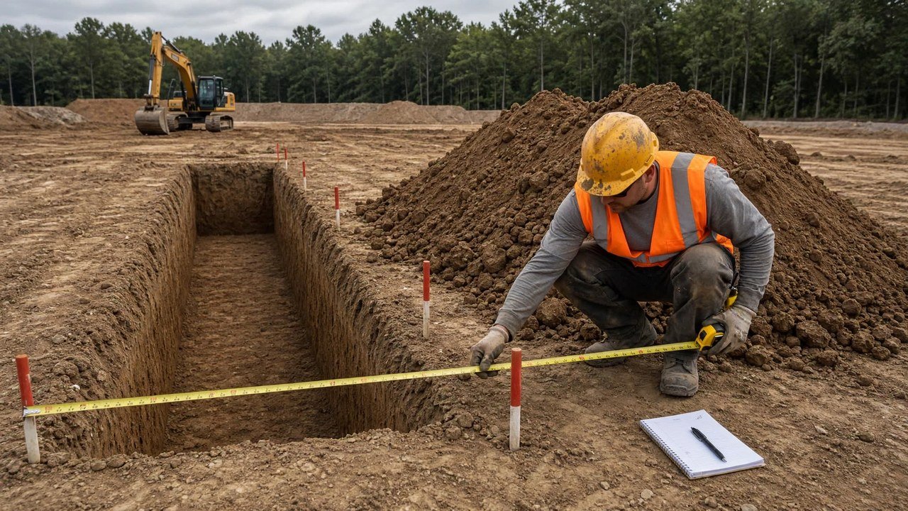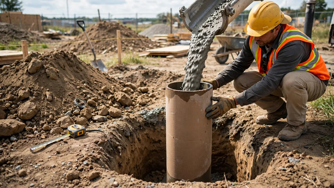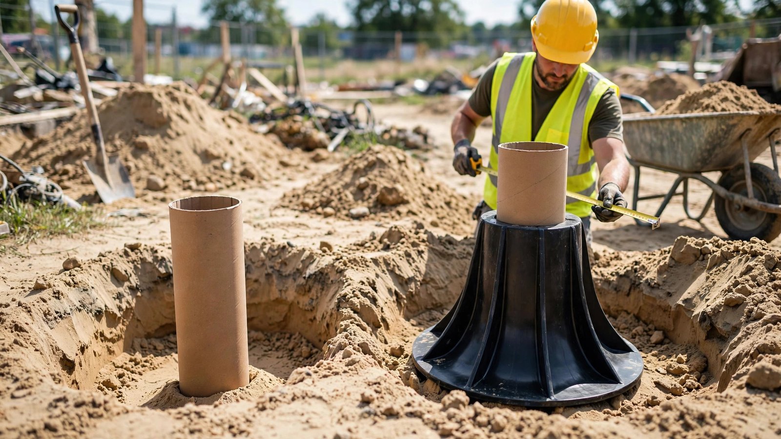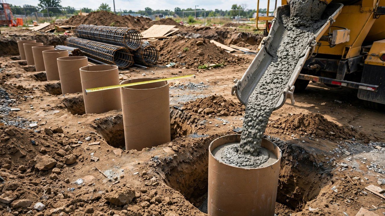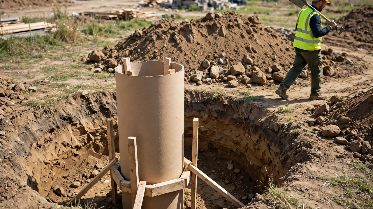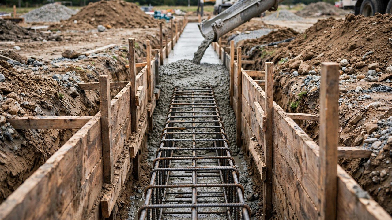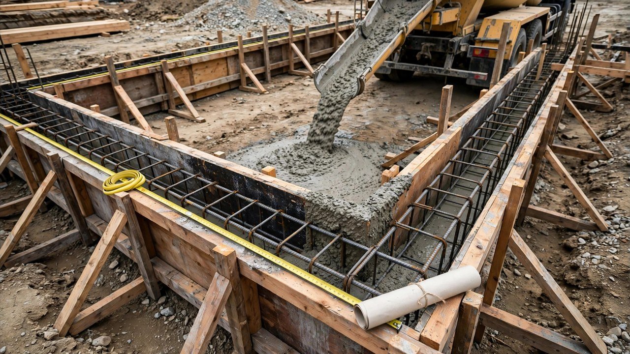
A grade beam concrete takeoff is one length, one cross-section, and one correction wherever the plan changes. This example works a 22.0 by 16.0 metre rectangular plan with a 500 by 800 millimetre beam, adds one widened column block with its overlap removed, and cross-checks the result in cubic yards. The final measured quantity is 31.25 cubic metres of beam concrete.
How much concrete does this grade beam plan need?
31.25 m³ of beam concrete. The main rectangle contributes 29.6 m³ from 74.0 m of centreline at 0.5 by 0.8 m. The widened column block adds a net 1.65 m³ after the beam concrete it replaces is removed from the main run. The blinding stays in a separate record; it is lean concrete, not beam concrete.
What are the inputs, and what method applies?
This method covers straight grade beam runs of constant width and depth, in forms or cast against a trimmed trench. It takes the beam width and depth from the approved drawings, the outside plan dimensions from the same drawings, and the poured depth from the top of the blinding to the top of the pour line. Choosing the beam dimensions is structural design, not quantity takeoff.
Volume = centreline length × width × depth
Centreline length = 2 × (L + B) − 4 × width
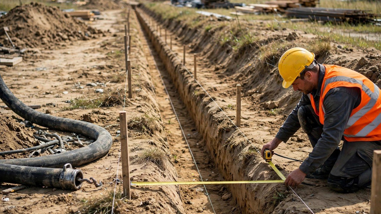
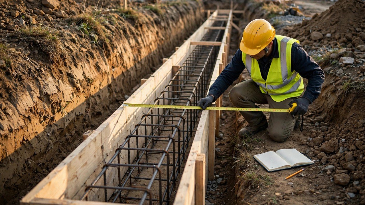
The second equation applies to rectangular plans with square corners. Run the tape along the beam centrelines so each corner counts once; the rectangular shortcut gives the same total.
Where a widened block sits over the beam run, the beam volume under it is already counted in the main rectangle. Add the block, then remove the replaced beam length from the main run.
Worked example: a 22.0 m by 16.0 m grade beam plan
A rectangular grade beam plan measures 22.0 m by 16.0 m on the outside faces. The beam is 500 mm wide and 800 mm deep, poured from the top of the blinding. One column junction carries a widened block 1.5 m by 1.5 m by 1.0 m deep, sitting over the beam run.
- Convert millimetres to metres: 500 mm = 0.5 m, 800 mm = 0.8 m.
- Outside perimeter = 2 × (22.0 + 16.0) = 76.0 m.
- Centreline length = 76.0 − 4 × 0.5 = 74.0 m.
- Main volume = 74.0 × 0.5 × 0.8 = 29.6 m³.
- Column block = 1.5 × 1.5 × 1.0 = 2.25 m³. Replaced beam = 1.5 × 0.5 × 0.8 = 0.6 m³. Net block = 2.25 − 0.6 = 1.65 m³.
- Total measured = 29.6 − 0.6 + 2.25 = 31.25 m³.
Result: 31.25 m³ of beam concrete, measured and unrounded until this point. Any project allowance goes in the order record with its own basis; it never edits this number.
| Segment | Centreline or replaced length (m) | Width (m) | Depth (m) | Volume (m³) |
|---|---|---|---|---|
| Main rectangle | 74.0 | 0.5 | 0.8 | 29.6 |
| Column block | n/a | 1.5 | 1.0 | 2.25 |
| Replaced beam under the block | 1.5 | 0.5 | 0.8 | −0.6 |
| Total measured beam concrete | 31.25 |
Blinding record (separate, lean concrete): 0.7 m wide × 0.1 m thick × 74.0 m = 5.18 m³. Record it with its own mix and rate; it is never part of the beam volume.
How does the result read in cubic yards?
Convert 31.25 m³ to cubic feet, then divide by 27.
31.25 × 35.314666721 = 1103.5833 ft³. 1103.5833 ÷ 27 = 40.8735 yd³.
Cross-check: 40.8735 × 0.764554857984 = 31.25 m³. The two paths agree, which confirms the conversion arithmetic, not the measurements.
What changes on other plans?
L-shaped or offset plans do not use the rectangular corner correction. Sum the straight runs on their centrelines and check every inside and outside corner overlap on the plan. Curved or battered sections need a zone takeoff with the radii from the drawings. Beams cast against an irregular trimmed trench are better measured as dug width times depth at several stations, averaged by run. Each widened section, haunch, and pile cap is a segment of its own with its actual geometry.
What does this example not decide?
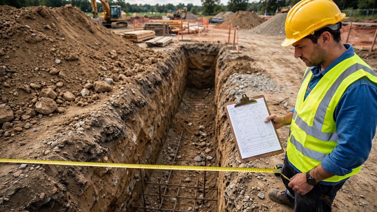
It sets no waste allowance, rounds no truck size, and approves no reinforcement, recess, or structural decision. Those entries belong in the order record with their own basis, covered in the grade beam ordering guide. Excavation and formwork follow the project's safety plan and the applicable workplace rules; measure inside the forms, or across the dug section, before the pour begins, not during placement.
Sources and scope
- Estimating Concrete and Rebar Quantities: documents the centreline, building-line and sectioning takeoff methods and the rectangular corner correction (outside perimeter − 4 × width).
- NIST Handbook 133 (2026), Appendix E: cubic-foot, cubic-yard, and cubic-metre unit relationships.
- OSHA 29 CFR 1926.703: U.S. workplace requirements for cast-in-place concrete formwork.
- OSHA 29 CFR 1926.651 and OSHA 29 CFR 1926.652: covered U.S. excavation conditions, inspections, and protective systems.
Source scope: the estimating handout documents the takeoff methods and corner correction; the worked fixtures on this page verify the arithmetic independently. NIST supports the unit relationships. OSHA supports the workplace safety context in covered U.S. work. None of these sources designs the beam, sets an allowance, or selects the order quantity for a specific project.
Review note: Saleem Sial owns the research and editorial record. Formula fixtures, source checks, build validation, and rendered QA form the internal publication gate. Waseem Sial, External Reviewer, Engineer, is listed for ongoing external review; no completed review date is claimed.
Enter the checked measurements in the Concrete Beam Calculator to total beam sections and estimate bags from a stated product yield. The grade beam measurement guide covers the field tape method in full, the grade beam mistakes checklist covers the ten errors that change the order, and the Foundation Quantity Planning Tools and Guides hub lists the related foundation calculators and guides.