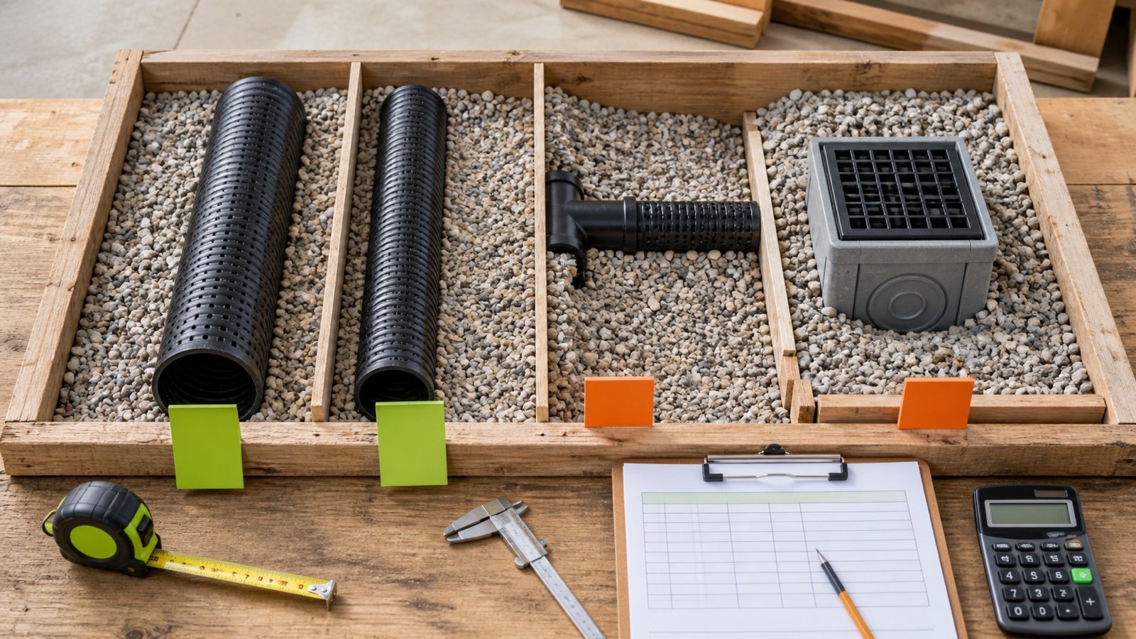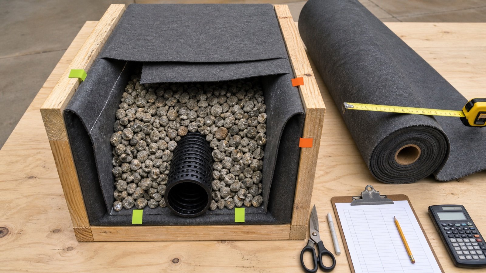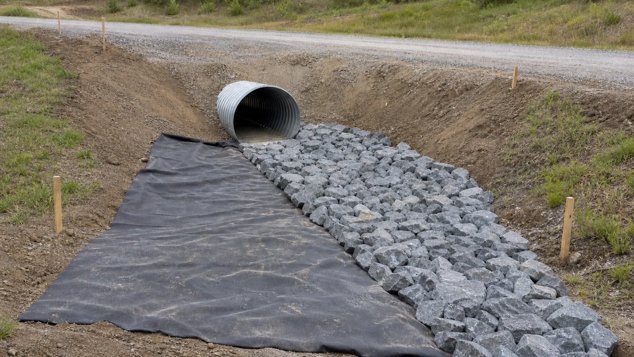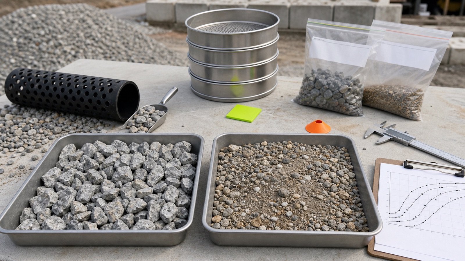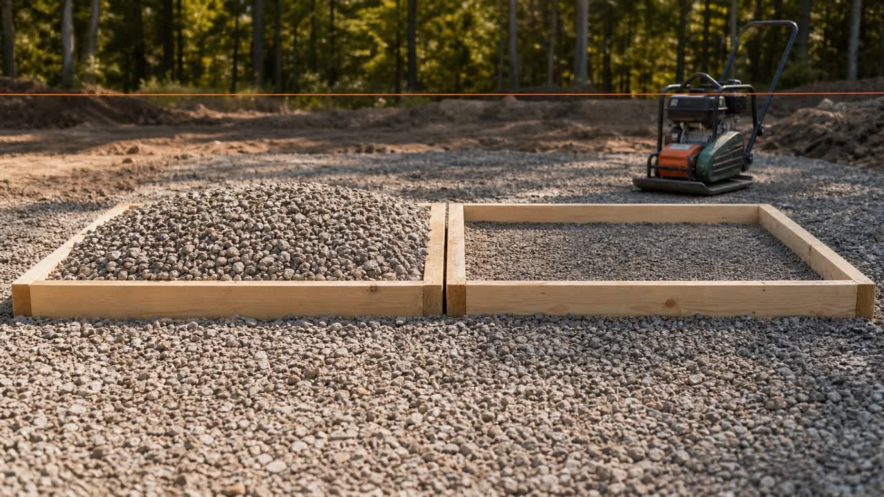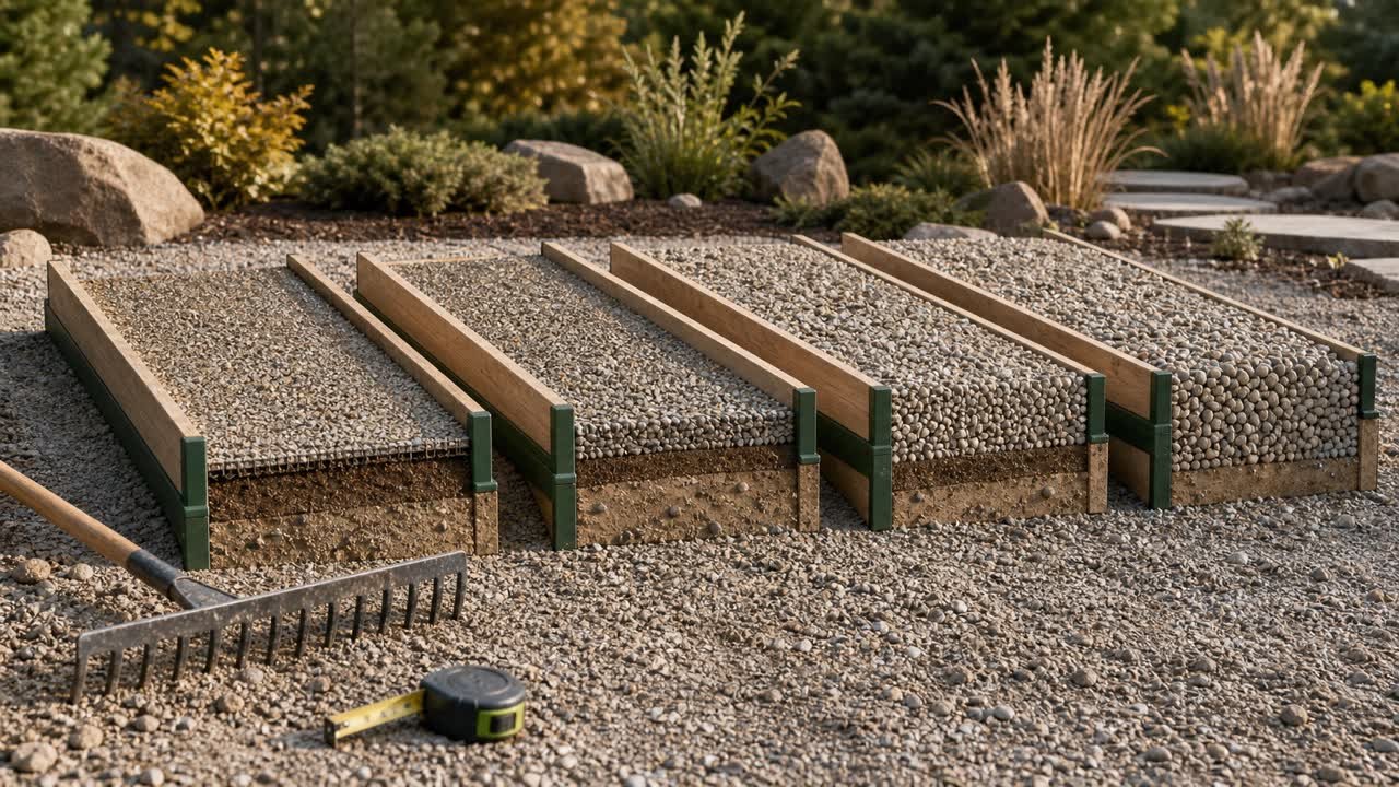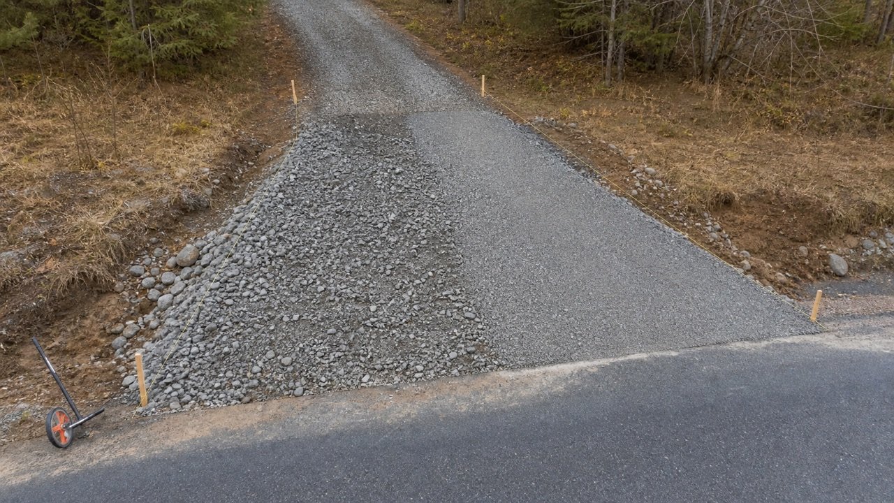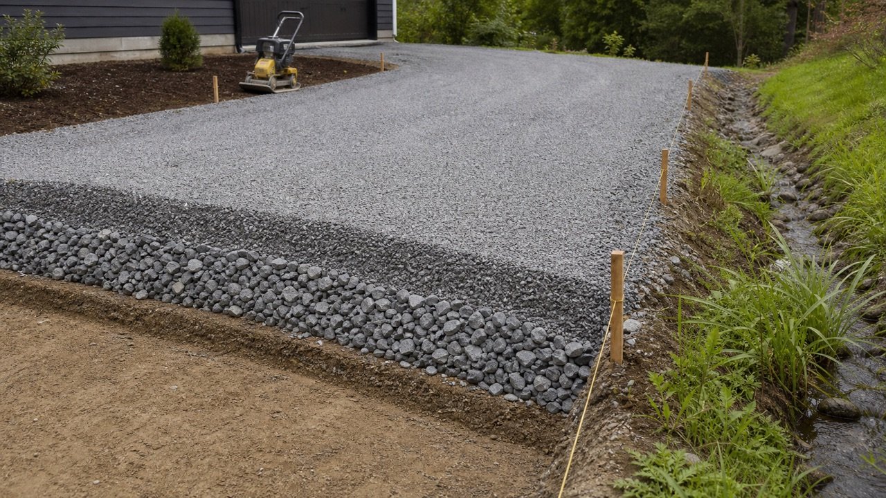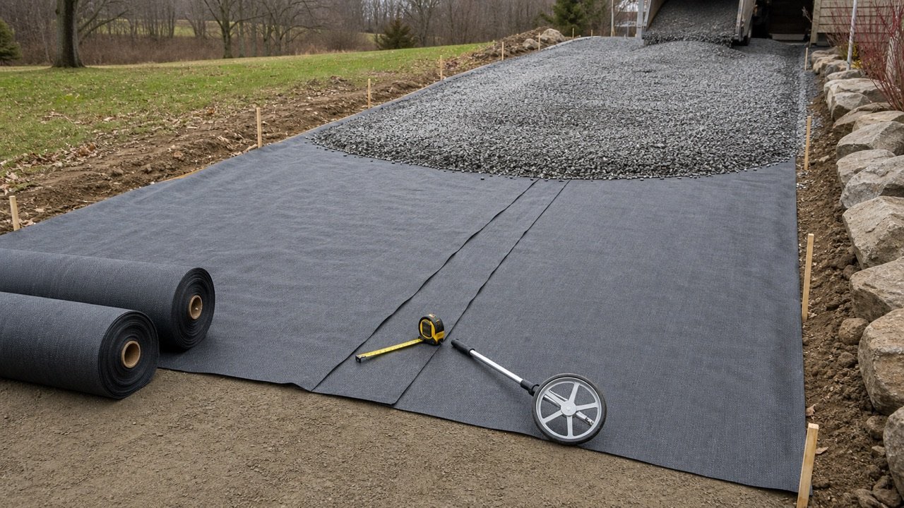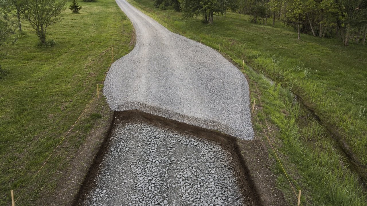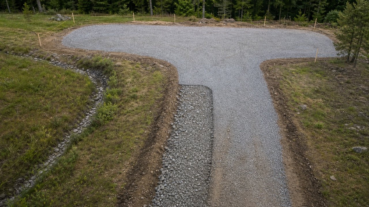
Resurfacing an existing gravel driveway starts with the difference between its prepared surface and the approved finished profile. One top-up depth works only when that difference is reasonably uniform across the measured area.
Survey thin areas, high spots, ruts, edges, crown, entrances, and fixed thresholds before ordering. The quantity should represent the gravel the finished profile needs after reshaping, not the full original driveway section.
How much gravel does an existing driveway need?
Calculate the positive vertical difference between target and existing elevations at measured points. Multiply each representative depth deficit by its plan area, add the fill zones, then subtract only the existing gravel that can be recovered and reused.
Fill depth = target elevation - prepared existing elevation
Uniform cubic yards = area in ft² × fill depth in inches ÷ 324
Uniform cubic metres = area in m² × fill depth in mm ÷ 1,000
When the difference is negative, record cut instead of subtracting it automatically from fill. Cut material reduces the imported order only after its gradation, cleanliness, moisture condition, location, and usable quantity are checked.
These formulas return finished geometric volume. A quarry load may be measured as loose volume or mass. Keep the compacted target, loose conversion, density, handling allowance, selling increment, and legal payload as separate entries.
Use the Driveway Gravel Calculator when one verified rectangular, uniformly tapered, or known-area section has one placed surface depth. Leave the base depth blank for a surface-only top-up. Use measured zones or cross-sections when the deficit changes.
When is a uniform top-up calculation acceptable?
Use a uniform depth only when a survey confirms that the prepared and target surfaces are approximately parallel over the stated area. Divide the driveway into zones when its width, deficit, profile, material, or treatment changes.
| Existing condition | Method | Reason |
|---|---|---|
| Prepared surface is consistent and target adds one parallel layer | Plan area × verified uniform depth | The layer is represented by one prism |
| Several broad areas have different deficits | Zone area × average zone depth | Each zone can use a separate representative depth |
| Crown, crossfall, or width changes along the driveway | Cross-sections at stations | Fill area changes with the profile |
| Irregular depressions remain after grading | Grid cells or bounded repair zones | One average can hide local depth changes |
| High spots and displaced shoulder gravel are present | Separate cut-and-fill survey | Recovered material may reduce imports after acceptance |
| Soft, wet, pumping, or failed areas remain | Repair investigation before resurfacing quantity | The base or subgrade scope is not defined |
A uniform screening estimate is useful for budgeting. It should be replaced by measured zones or cross-sections when the site does not match the uniform assumption.
Which resurfacing sections fit the Driveway Gravel Calculator?
The Driveway Gravel Calculator accepts one rectangle, one uniform taper, or one checked plan area at a time. Enter only the verified placed surface depth for a top-up, and keep the base layer blank unless the approved work includes base replacement.
| Measured section | Calculator action | Quantity boundary |
|---|---|---|
| Constant-width section with one verified deficit | Use rectangle mode | Length × width × placed surface depth |
| Straight section whose width changes uniformly | Use uniform-taper mode | Check at least one intermediate width before accepting the taper |
| Survey or drawing gives a checked net area | Use known-area mode | Confirm units, exclusions, revision, and one representative depth |
| Several zones have different depths or products | Run each suitable zone separately | Add unrounded quantities by product and avoid overlap |
| Crown correction, changing crossfall, ruts, or local cut | Use the cross-section or grid methods on this page | One whole-driveway depth does not represent the measured profile |
What should be surveyed before resurfacing?
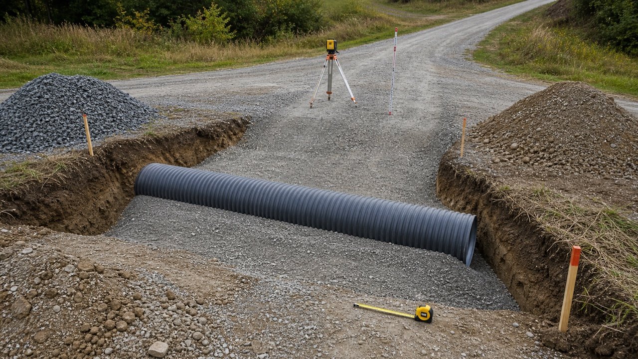
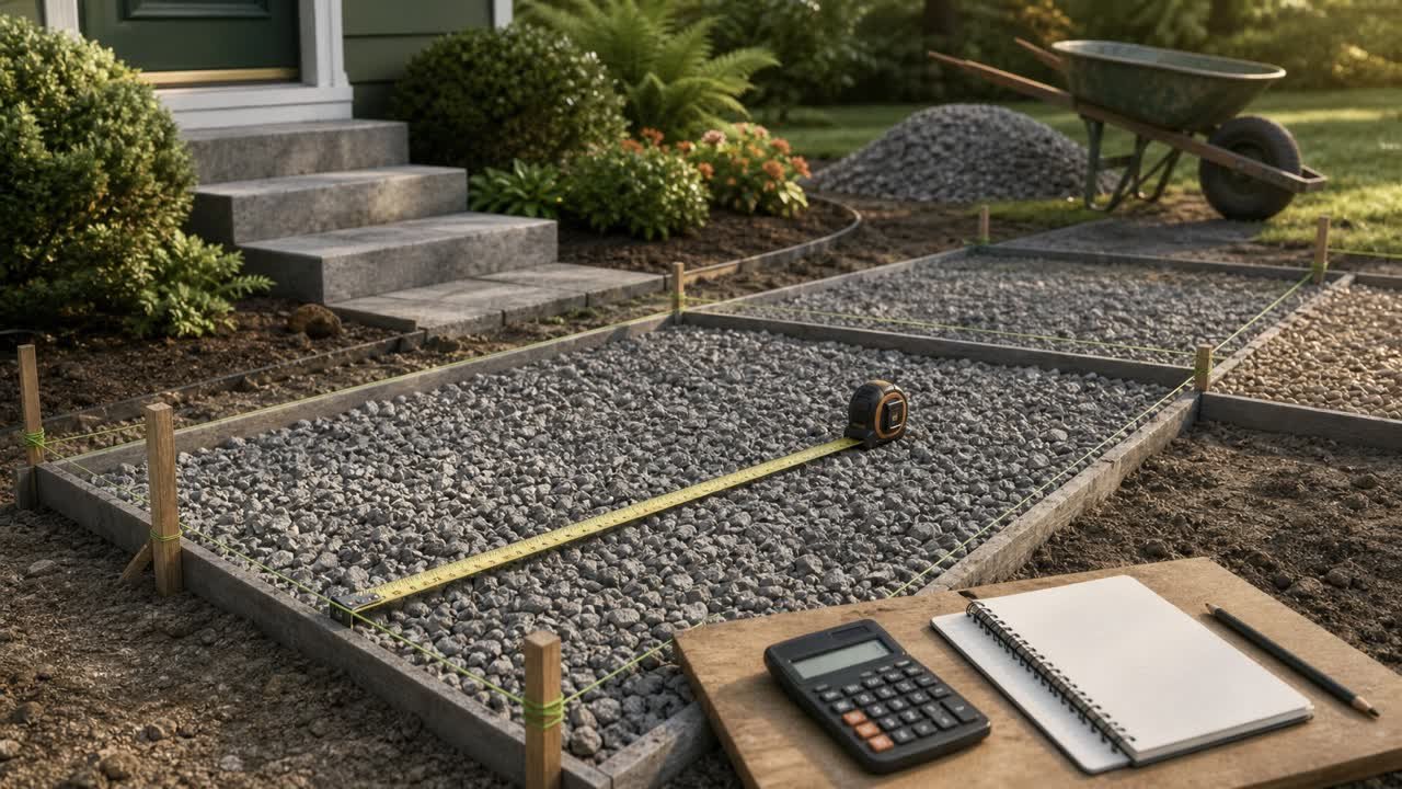
Record the center and both edges at stations, then add points at every grade break, rut, pothole, curve, turnout, culvert, entrance, and fixed elevation. Use one checked benchmark or datum.
- Define which grading, scarifying, cleaning, and repair work occurs before the resurfacing survey.
- Mark the resurfacing limits and exclude areas with a different material or repair treatment.
- Record driveway width and horizontal station distances.
- Measure centerline and edge elevations without changing the datum.
- Establish target elevations from the approved crown, crossfall, longitudinal grade, and tie-ins.
- Calculate fill depth at each point and mark negative differences as cut.
- Draw fill boundaries between measured points.
- Repeat critical readings after grading and before final ordering.
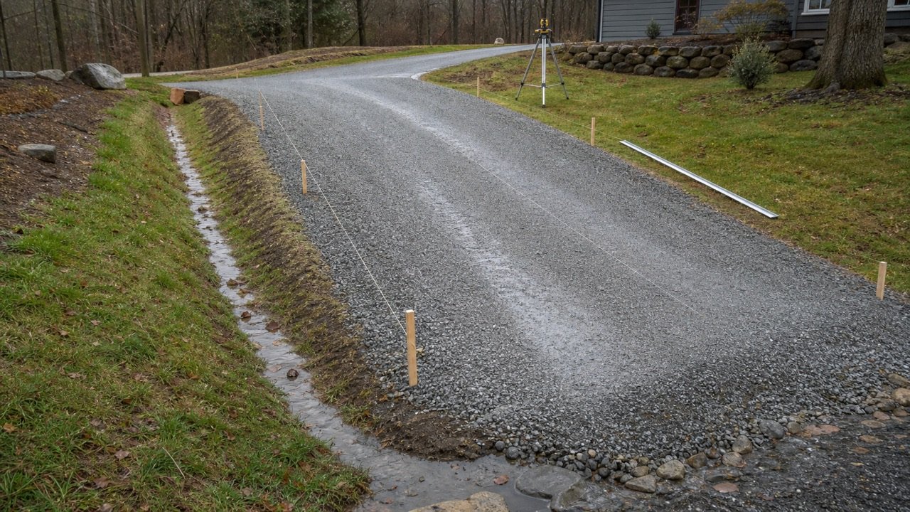
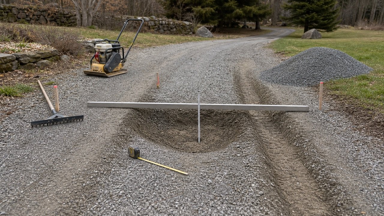
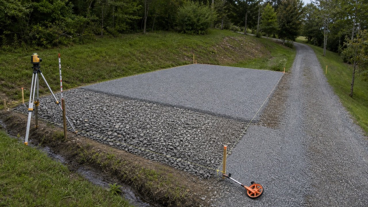
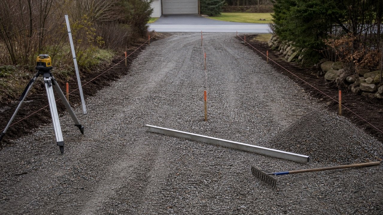
A straightedge laid over a rutted surface can reproduce its damaged profile. Grade stakes, string lines, a laser or optical level, or another project-approved method should reference the intended finished surface.
Use the gravel driveway drainage and grade guide to check crown, crossfall, longitudinal grade, and the receiving outlet before assigning target elevations.
Worked example for a verified uniform top-up
A 120 ft-long, 12 ft-wide driveway has been graded. Field checks confirm that a 1.5 in compacted vertical layer represents the remaining difference to the approved parallel target profile.
| Step | Calculation | Result |
|---|---|---|
| Plan area | 120 × 12 | 1,440 ft² |
| Compacted volume | 1,440 × 1.5 ÷ 324 | 6.666667 yd³ |
| Independent check | 120 × 12 × (1.5 ÷ 12) ÷ 27 | 6.666667 yd³ |
The result is not automatically the order quantity. The supplier's product, loose-to-compacted relationship, selling unit, and delivery increment must still be documented.
How do measured zones change the quantity?
Divide the driveway where the prepared-to-target deficit changes. Measure each zone's net area and representative average depth, then sum unrounded volumes.
| Zone | Area | Average fill | Compacted volume |
|---|---|---|---|
| A | 480 ft² | 1.25 in | 1.851852 yd³ |
| B | 360 ft² | 2.00 in | 2.222222 yd³ |
| C | 240 ft² | 0.75 in | 0.555556 yd³ |
| Total | 4.629630 yd³ | ||
The NIST conversion gives about 3.539606 m³ for the displayed total. The zone method uses 1,080 ft² of measured fill area. Do not add excluded high spots, repaired potholes, or sound areas again.
How are changing cross-sections calculated?
Calculate fill area between the prepared and target profile at each station. For a segment that changes approximately linearly, multiply its length by the average of the 2 end areas.
Segment volume = length × (start fill area + end fill area) ÷ 2
Example fill areas at stations 0, 15, and 30 ft are 0.60, 1.20, and 0.30 ft².
- Station 0 to 15: 15 × (0.60 + 1.20) ÷ 2 = 13.50 ft³.
- Station 15 to 30: 15 × (1.20 + 0.30) ÷ 2 = 11.25 ft³.
- Total: 13.50 + 11.25 = 24.75 ft³.
- Convert: 24.75 ÷ 27 = 0.916667 yd³.
Add stations where the fill shape changes abruptly. Average-end-area geometry does not represent a sudden step, separate depression, or unmeasured widening.
Does a crowned driveway need a special volume factor?
A parallel layer of uniform vertical thickness over a prepared crown uses plan area multiplied by that vertical thickness. Reshaping a flat, leaning, rutted, or reverse-crowned surface needs the difference between existing and target cross-sections.
| Situation | Quantity basis |
|---|---|
| Target and existing profiles are parallel | Plan area × uniform vertical thickness |
| Center must be raised more than both edges | Cross-sectional fill area × length |
| One edge is high and the opposite edge is low | Separate cut and fill across each cross-section |
| Existing gravel can be pulled from edges toward center | Measure recoverable cut and remaining imported fill |
| Target crown changes along the route | Station sections and segment volumes |
Do not add a fixed crown percentage to a top-up order. The extra or recovered volume comes from the measured profile difference.
Which elevations can limit a top-up?
Check fixed and drainage-critical elevations before raising the driveway. Extra gravel can create a trip edge, block runoff, bury a restraint, reduce a clearance, or send loose aggregate onto a public surface.
- Garage doors, slabs, thresholds, and building damp-control details.
- Paved-road or sidewalk tie-ins and permit limits.
- Gate sweeps, tracks, posts, and vehicle-clearance points.
- Channel drains, catch basins, culvert inlets, ditches, and swales.
- Edging, retaining walls, bridge decks, cattle grids, and utility covers.
- Accessible routes, steps, ramps, and pedestrian crossings.
- Snowplow transitions and loose-stone containment at entrances.
A top-up that cannot fit below a fixed elevation may require cutting, removing, or rebuilding existing material. That work changes disposal, base exposure, and imported quantities.
When can recovered gravel reduce the import?
Recovered gravel can offset fill when reshaping moves suitable material from high areas, shoulders, or windrows into the target section. Survey the material balance and verify that the recovered material meets the required use.
| Check | Record |
|---|---|
| Source | Station, shoulder, high area, stockpile, or scarified surface |
| Material | Course, gradation, contamination, segregation, moisture, and oversize |
| State | In place, excavated, loose stockpile, or compacted |
| Quantity | Measured cut, stockpile survey, or accepted load records |
| Losses | Rejected soil, vegetation, sediment, spillage, or inaccessible material |
| Approval | Project specification, supplier, contractor, or responsible reviewer |
The EPA-hosted gravel-road manual describes reshaping existing road and shoulder material before replacing surface gravel. That public-road maintenance principle does not prove that every recovered residential material is suitable.
How does a metric top-up calculation work?
Multiply square metres by millimetres of verified average compacted fill and divide by 1,000. An 85 m² zone with a 32 mm average deficit needs:
85 × 32 ÷ 1,000 = 2.72 m³
The independent check is `85 × 0.032 = 2.72 m³`. Keep millimetres and metres out of the same multiplication until the depth is converted or the division by 1,000 is included.
How is compacted fill turned into a supplier order?
Convert only after the measured compacted geometry and reusable-material balance are complete. Ask the supplier which state and unit its quote represents.
- Sum compacted surface fill by zone or station segment.
- Add separately measured transitions and approved local repairs.
- Subtract accepted reusable material in a compatible material state.
- Apply a documented loose-to-compacted conversion if the seller quotes loose volume.
- Use a product-specific bulk density if the seller quotes mass.
- Add a justified handling allowance separately.
- Round once to the actual selling increment.
- Confirm truck type, legal payload, access, dump location, fees, and partial-load policy.
The EPA-hosted quantity appendix includes loose gravel coverage and truck-spreading tables. Its chart is explicitly uncompacted and includes its own compaction warning. Use current project or supplier evidence instead of copying that historic factor into a residential order.
Check material states with the gravel compaction guide, then use the Gravel Calculator for approved uniform zones.
Common resurfacing quantity mistakes
- Using a standard top-up depth without surveying the prepared surface.
- Calculating the full original driveway depth instead of the missing depth.
- Using the deepest rut as the average across the driveway.
- Measuring before grading but ordering for the after-grading profile.
- Counting pothole repair and resurfacing volume over the same area twice.
- Treating high points as automatic negative fill without checking reuse.
- Applying one width through turnouts, curves, and tapered entrances.
- Adding a fixed percentage for crown.
- Raising the surface above a garage, drain, gate, or public-road tie-in.
- Converting volume to tons with an unrelated density.
- Combining compaction, settlement, waste, and contingency into one hidden factor.
- Rounding each small zone before adding the project.
- Using a loose coverage table as finished compacted depth.
- Resurfacing soft or wet failures before their repair scope is defined.
What should the resurfacing quantity record contain?
- Project, location, date, weather, surface condition, and work limits.
- Preparation state used for the existing survey.
- Benchmark, datum, instrument, stations, offsets, and check readings.
- Existing and target center and edge elevations.
- Fill boundaries, cut boundaries, widths, depths, and cross-sectional areas.
- Separate repair, base, surface, drainage, and transition quantities.
- Recovered-material source, state, suitability, quantity, and losses.
- Unrounded compacted volume and independent calculation check.
- Supplier product, loose conversion or density basis, selling unit, and quote date.
- Threshold, outlet, permit, utility, traffic, and delivery constraints.
- Prepared by, checked by, revision, assumptions, and unresolved items.
Safety and scope
Keep people clear of traffic, graders, loaders, compactors, and dumping trucks. Follow equipment instructions, locate buried and overhead utilities, control dust, maintain safe access, and protect open drainage features.
Obtain project-specific advice for weak or pumping ground, groundwater, steep slopes, retaining conditions, washouts, public-road work, unusual loading, utilities, drainage structures, or repeated failure. Drawings, specifications, permits, local rules, and a qualified professional can control the target profile and material.
This page checks geometric resurfacing quantities. It does not design the pavement section, approve aggregate, establish compaction procedure, size drainage, certify the subgrade, or authorize work at a public connection.
Sources and source scope
- FHWA Roadway/Roadside Maintenance resources: current official access point for the gravel-road construction and maintenance guide and the drainage-maintenance guide.
- FHWA and South Dakota LTAP, Gravel Roads Construction & Maintenance Guide: surface shape, drainage, material loss, grading, reuse, and compaction context for gravel roads.
- US EPA, Gravel Roads: Maintenance and Design Manual resource page: official access to routine maintenance, surface gravel, drainage, and quantity-calculation sections.
- Appendix C: Quantity Calculations: historic loose coverage and truck-spreading tables and their stated compaction scope.
- NIST Guide to the SI, Appendix B.8: cubic-foot and cubic-yard conversion factors.
Scope: the road manuals support the maintenance sequence and quantity context within public-road programs. They do not set one residential top-up depth, compaction factor, density, or material. The worked examples verify geometry for the stated measurements.
Define repair quantities with the pothole and rut repair guide, check the intended section in the gravel driveway depth guide, review material options in the gravel size chart, or return to the Gravel planning hub.