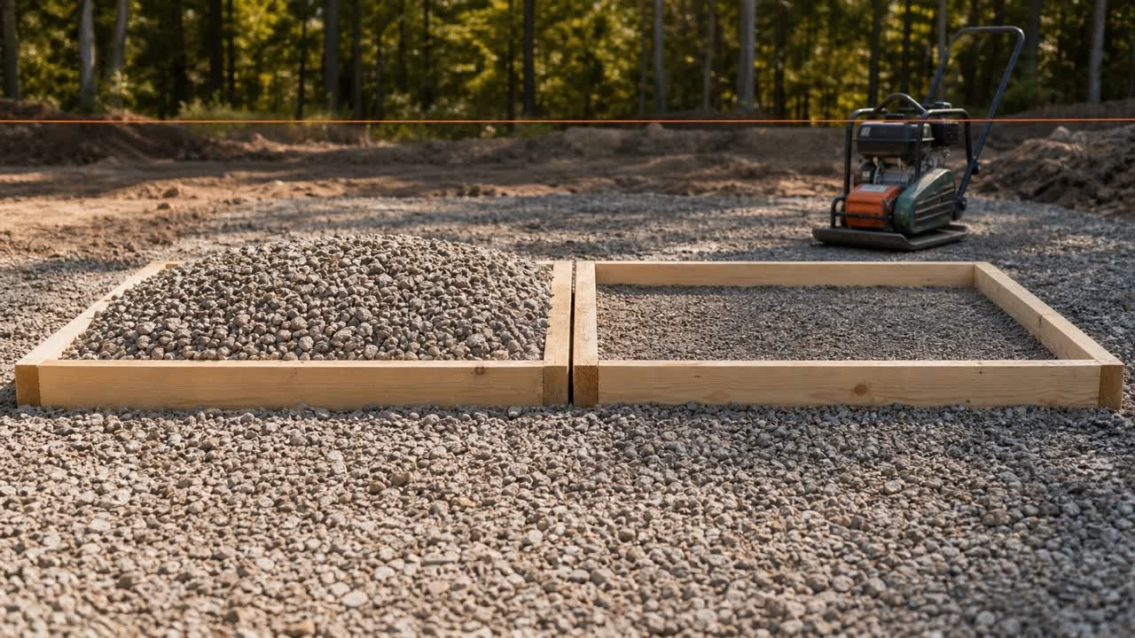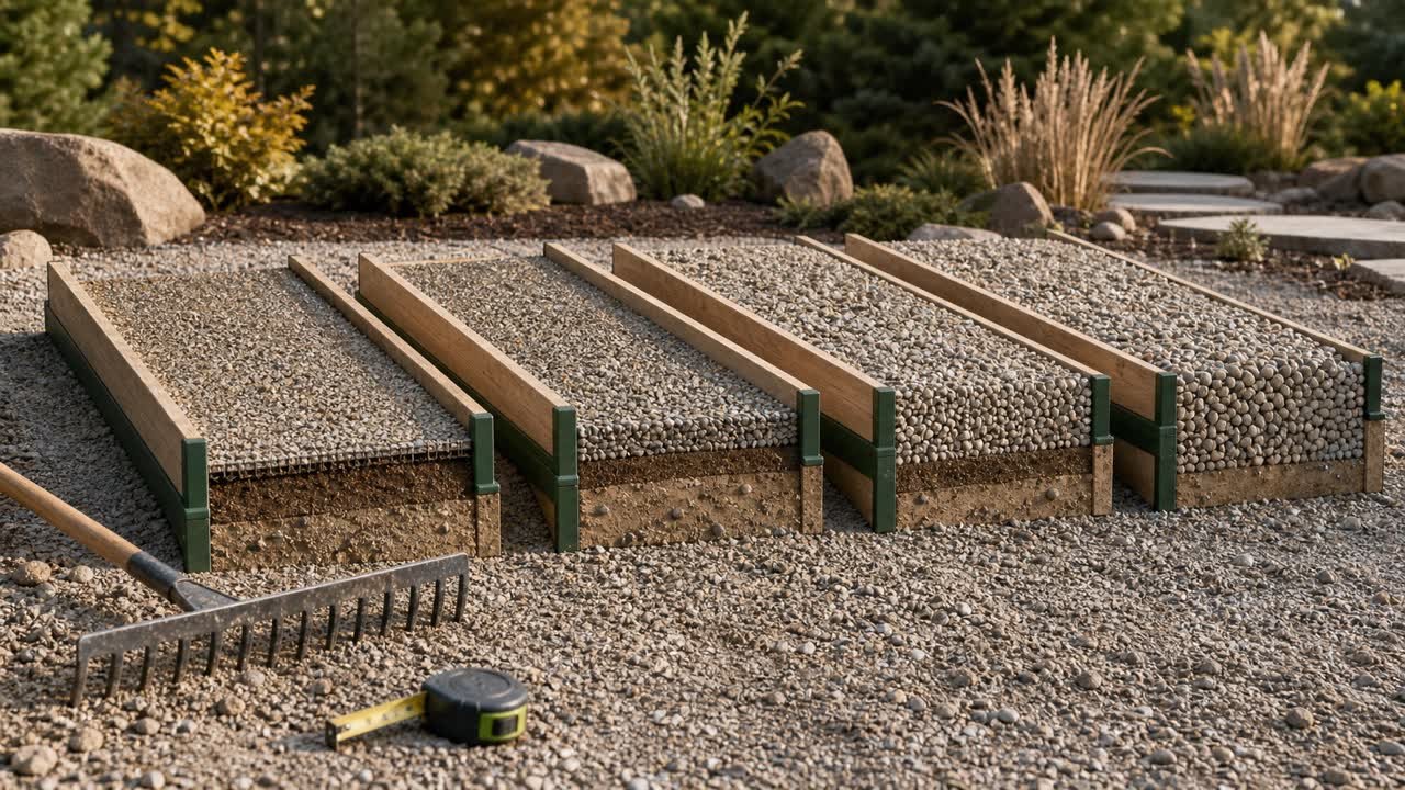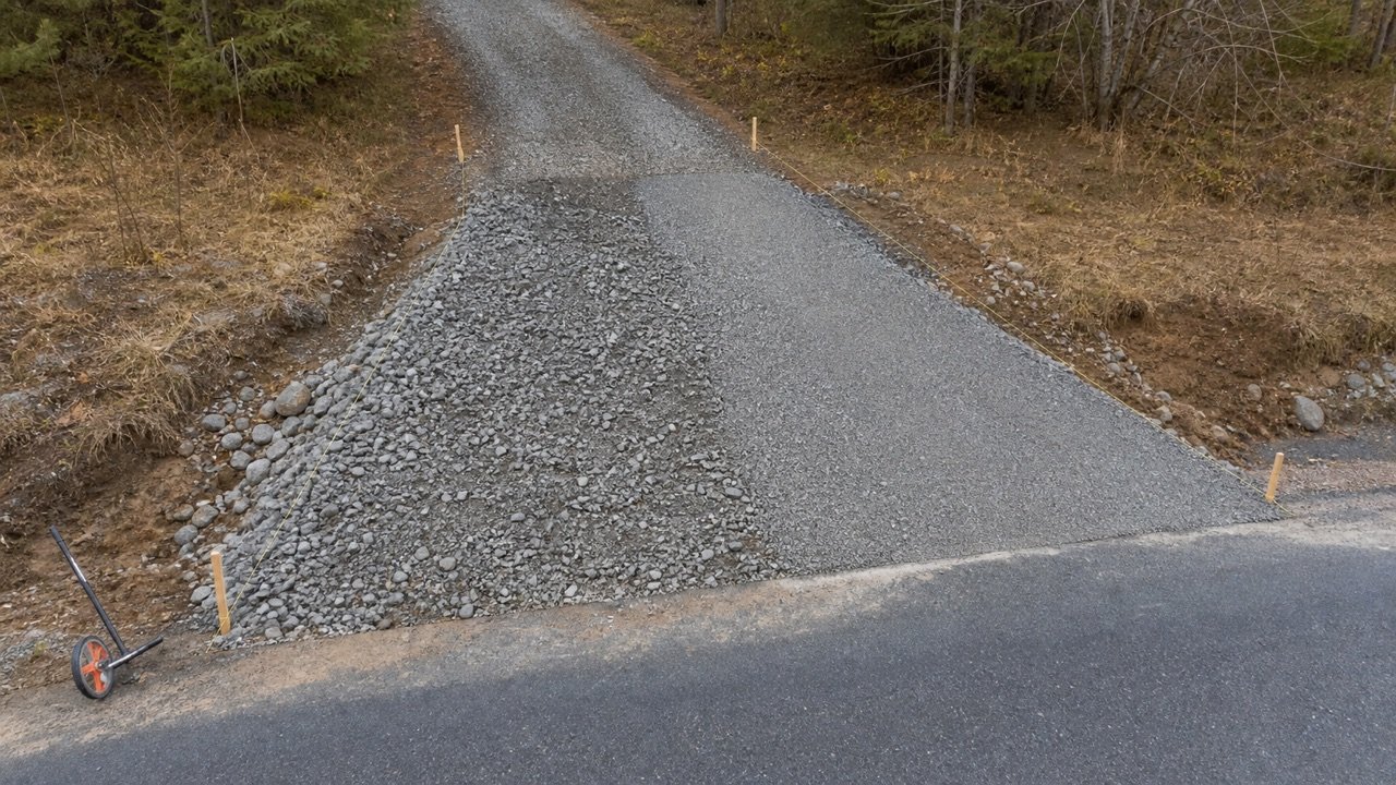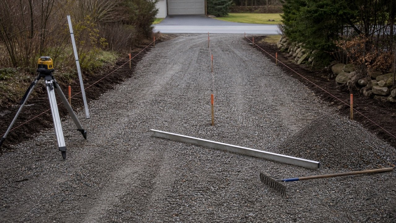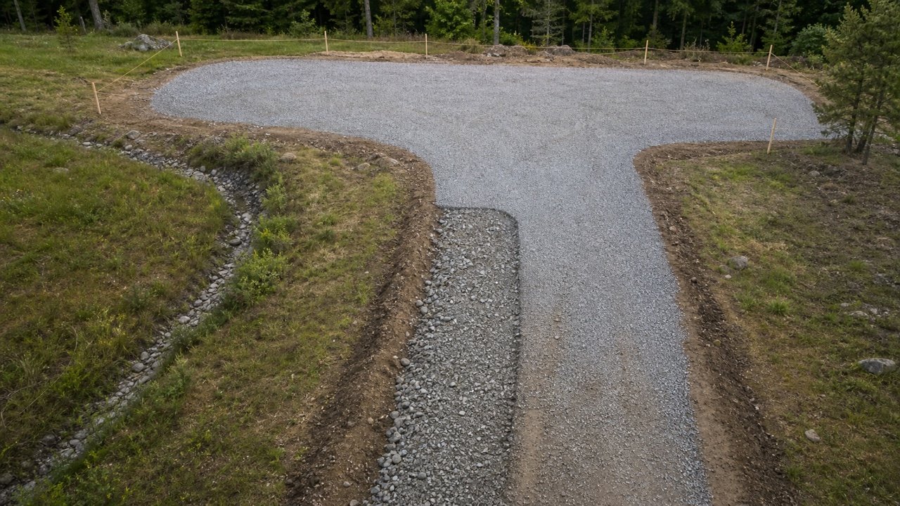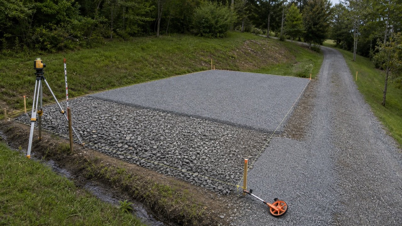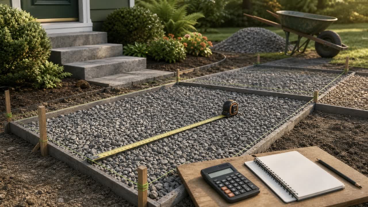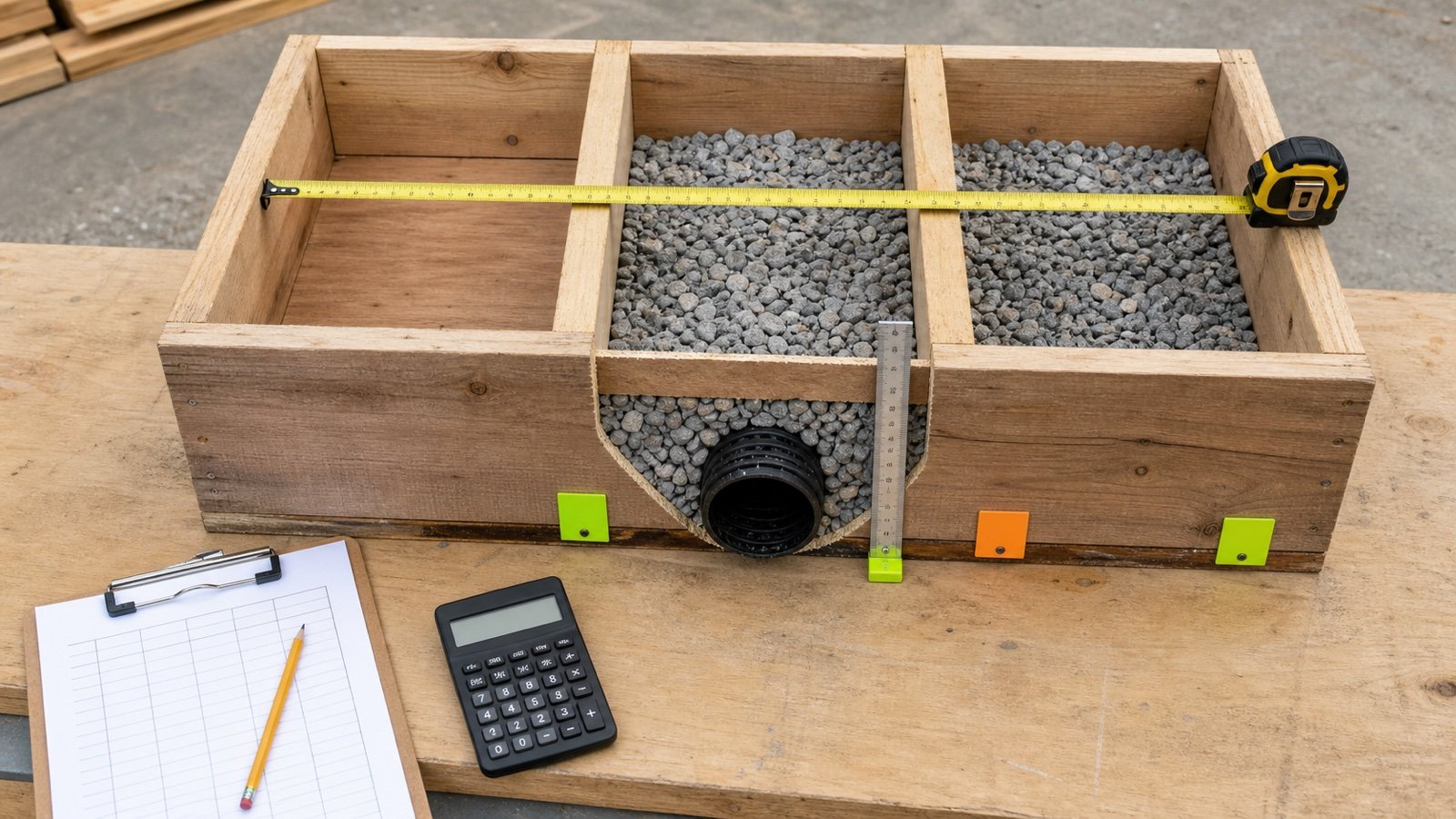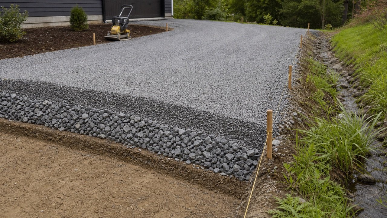
A gravel driveway estimate needs a defined cross-section before it needs tonnage. Measure the footprint, confirm the accepted compacted thickness of each material, and calculate the layers separately.
The appropriate depth depends on the vehicles and load repetitions, subgrade support, water, climate, aggregate properties, construction method, and maintenance plan. A quantity guide can check the arithmetic after the design inputs have been set.
How deep should a gravel driveway be?
Use the depth stated in the approved project cross-section or establish it from a site-specific design. There is no single depth that suits every residential driveway, access road, soil, drainage condition, or climate.
FHWA guidance for aggregate-surfaced roads bases thickness on inputs such as traffic, subgrade strength, climate, allowable rutting, aggregate loss, and material durability. USDA NRCS guidance likewise includes vehicle type, loads, soils, climate, drainage, and intended use in access-road design.
This page calculates compacted geometric volume from an already selected layer thickness. It does not select the structural section, aggregate specification, geotextile, drainage system, or acceptance method.
Small passenger vehicles on firm, well-drained ground and repeated delivery trucks on weak, wet soil do not impose the same demand. A copied 4 in, 6 in, or 8 in value can produce a neat calculation and an unsuitable road.
Which depth belongs in the material calculation?
Enter the accepted compacted or placed thickness for the named aggregate layer. Do not mix it with excavation depth, loose spread depth, rut depth, or the total thickness of several different materials.
| Depth | What it measures | How it affects quantity |
|---|---|---|
| Structural layer depth | The project-defined accepted thickness of one base, subbase, or surface material | Use it with that layer's net area to calculate compacted geometric volume |
| Total aggregate depth | The sum of all accepted aggregate-layer thicknesses | Useful for an elevation check, but not for ordering one mixed product |
| Excavation depth | The vertical distance removed to reach the prepared surface | Controls excavation quantity and available build-up; it may include removed soil or existing material |
| Loose lift depth | The thickness before the specified compaction process | Use only with a documented loose-to-compacted relationship |
| Maintenance top-up depth | The measured deficit between the current and target surface | Calculate only the repair or replenishment area after the cause of the loss is assessed |
| Rut depth | A local depression measured from a chosen reference surface | It does not prove that filling the rut alone will repair the underlying problem |
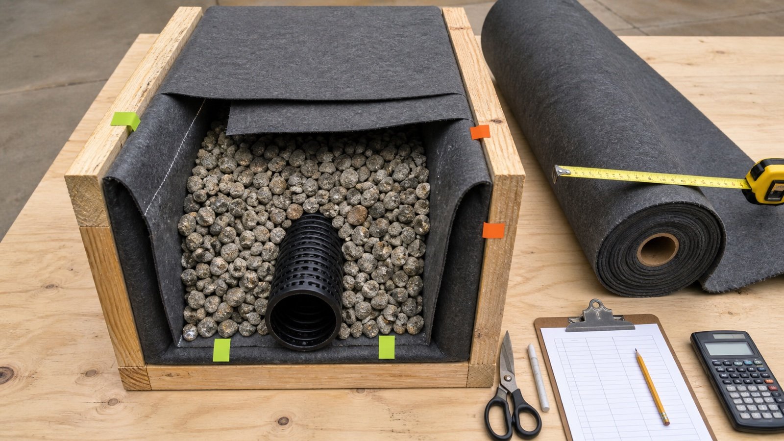
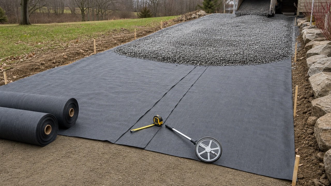
A geotextile is normally represented by its specified area and overlap, not by adding a fictional inch to the aggregate depth. Any cushioning, cover, or granular separation layer shown in the project documents is calculated as its own material.
What inputs should be confirmed before calculating?
Record the plan dimensions, finished levels, project-defined layers, and the conditions used to select them. A short input sheet is more useful than a hidden default.
- Net length and width, including curves, turnouts, parking bays, aprons, and excluded areas.
- Existing and target elevations at the garage, road connection, drainage outlets, doors, gates, and other fixed points.
- Prepared-subgrade condition and any soil investigation, proof-roll record, or design strength input.
- Expected passenger vehicles, delivery vehicles, trailers, recreational vehicles, service trucks, and load frequency.
- Water table, runoff route, crossfall, ditches, culverts, roof discharge, and low areas.
- Climate, freeze-thaw exposure, snow-removal method, seasonal wet periods, and construction season.
- Material name, source, gradation or specification, and accepted compacted thickness for each layer.
- Compaction method and acceptance requirement named by the project documents.
- Supplier selling unit, documented bulk density or yield, minimum order, rounding increment, and delivery limits.
USDA NRCS calls for plans and specifications to show the road's width, length, profile, typical cross-sections, surface-treatment type and thickness, subbase preparation, grading, drainage, and material requirements. That record also gives the estimator a traceable quantity basis.
How do you calculate each gravel layer?
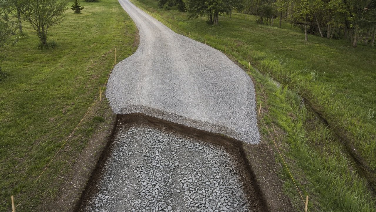
Multiply the net area covered by that material by its accepted compacted thickness. Convert the result to cubic yards or cubic metres, then repeat the calculation for every different layer or footprint.
Cubic yards = area in square feet × compacted depth in inches ÷ 324
Cubic metres = area in square metres × compacted depth in millimetres ÷ 1,000
The imperial denominator is 12 in/ft multiplied by 27 ft³/yd³. Keep the unrounded volume for later conversions.
For a rectangle, area is length multiplied by width. Break an irregular driveway into measured shapes or surveyed segments, calculate their areas, and subtract islands or other excluded zones. Use a separate footprint where a base extends beyond the surface course.
Use the Driveway Gravel Calculator to calculate base and surface layers separately from the driveway footprint and each accepted compacted depth. Label each result as compacted geometric volume before applying a documented state conversion or supplier rounding.
Worked imperial example
A rectangular driveway is 60 ft long and 12 ft wide. Its project cross-section specifies a 5 in compacted base and a 2 in compacted surface course over the same 720 ft² footprint.
| Step | Calculation | Compacted volume |
|---|---|---|
| Plan area | 60 × 12 | 720 ft² |
| Base layer | 720 × 5 ÷ 324 | 11.111111 yd³ |
| Surface layer | 720 × 2 ÷ 324 | 4.444444 yd³ |
| Total geometric volume | 11.111111 + 4.444444 | 15.555556 yd³ |
An independent check uses the combined 7 in depth: 720 × 7 ÷ 324 = 15.555556 yd³. The combined value checks the geometry, but the order still contains 11.111111 yd³ of the specified base material and 4.444444 yd³ of the specified surface material before state conversion and supplier rounding.
Worked metric example
A driveway is 18 m long and 3.6 m wide. The project requires a 140 mm compacted base and a 50 mm compacted surface course over the same 64.8 m² area.
| Step | Calculation | Compacted volume |
|---|---|---|
| Plan area | 18 × 3.6 | 64.8 m² |
| Base layer | 64.8 × 140 ÷ 1,000 | 9.072 m³ |
| Surface layer | 64.8 × 50 ÷ 1,000 | 3.240 m³ |
| Total geometric volume | 9.072 + 3.240 | 12.312 m³ |
The direct check is 64.8 × 0.190 = 12.312 m³. These values are compacted geometry, not delivered loose volume or tonnes.
How does finished elevation check the layer schedule?
Add the accepted compacted layer thicknesses to the accepted prepared-surface elevation. Compare the calculated level with the controlling finished elevation before material is ordered.
Calculated finished elevation = prepared-surface elevation + total accepted layer thickness
Suppose the prepared surface is at elevation 100.000 m. A 140 mm base and 50 mm surface produce a calculated finished elevation of 100.190 m.
If the controlling finished elevation is 100.160 m, the cross-section and prepared surface conflict by 30 mm. Do not hide that conflict by reducing a layer without approval or by rounding the quantity. The prepared level, layer design, or target level must be resolved by the responsible person.
| Record | Example | Check |
|---|---|---|
| Prepared surface | 100.000 m | Surveyed or accepted datum |
| Compacted base | +0.140 m | Project-defined accepted depth |
| Compacted surface | +0.050 m | Project-defined accepted depth |
| Calculated finish | 100.190 m | Compare with garage, road, drainage, and other controls |
How do loose volume, density, and order quantity fit in?
Calculate compacted geometry first. Convert that result with project- or product-specific evidence, then apply a separate documented handling allowance and the supplier's selling increment.
- Calculate the compacted geometric volume for each material.
- Use a documented loose-to-compacted factor when the supplier quantity and required layer use different material states.
- Convert volume to mass only with a representative bulk density for the selected product and stated moisture or measurement condition.
- Add a handling allowance only when site records, delivery method, trimming, or measurement uncertainty supports it.
- Apply supplier minimums and selling increments last.
The gravel compaction guide explains how to establish and state a loose-to-compacted factor. The gravel weight chart explains why product and material state matter when converting volume to mass.
A fixed 10% or 15% addition cannot automatically represent compaction, handling, uneven excavation, settlement, and supplier rounding. Those are different causes with different evidence.
How should a maintenance top-up be measured?
Measure the actual surface deficit over defined repair zones and restore the required profile. Do not reorder the full original structural depth unless the driveway is being reconstructed to that depth.
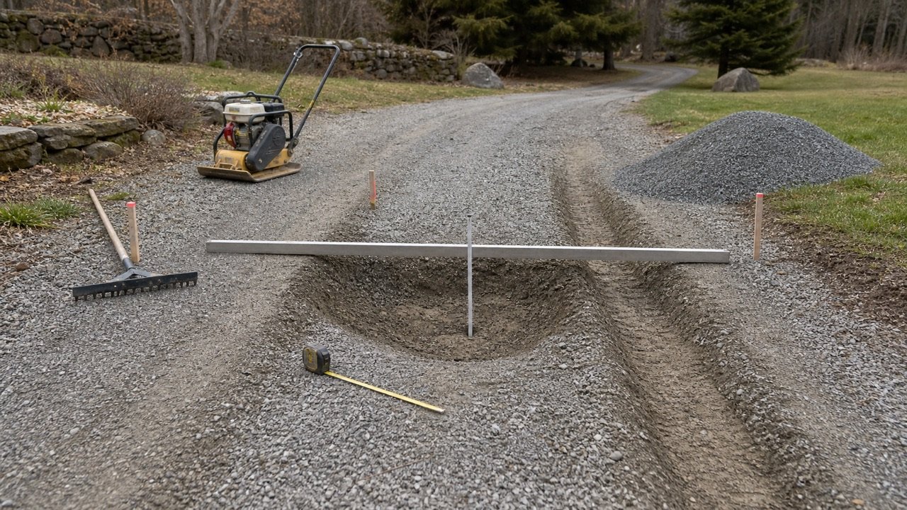
A simple top-up quantity can use measured area multiplied by the accepted average replenishment depth, but an average should represent enough readings across the zone. Separate isolated potholes, long wheel ruts, edge loss, and broad surface depletion when their depths or repair methods differ.
Repeated rutting, pumping fines, standing water, or rapid stone loss can indicate a subgrade, drainage, confinement, material, or maintenance problem. Filling the depression may restore the surface briefly while leaving the cause in place.
The gravel coverage guide gives area coverage for a known volume and depth. Use it after the repair depth and footprint have been measured.
How do drainage and crossfall affect the quantity?
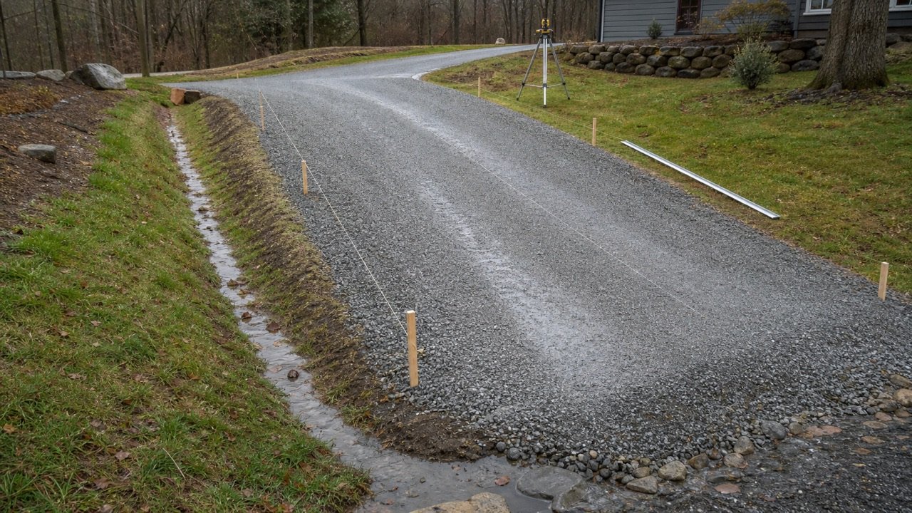
The finished profile must route water to an approved outlet without trapping it against buildings, sending it onto a road or neighboring property, or eroding the driveway edge. Follow the project grading plan and local requirements.
USDA NRCS guidance for access roads calls for drainage sized to the intended use and runoff conditions. Its national standard gives cross-slope ranges for its own access-road scope, but a residential driveway still needs a site-specific grade that fits its road connection, garage, soils, runoff, and local rules.
A crowned or cross-sloped surface has varying elevations across its width. For ordinary quantity planning, a uniform-thickness layer over a sloped prepared surface still uses plan area multiplied by the specified normal or vertical thickness according to the project measurement convention. Complex cross-sections, ditches, shoulders, and superelevated curves should be taken from surveyed sections or a design model.
When can geotextile or stabilization change the section?
Weak bearing soils or a need to separate surfacing from foundation soil can lead to a specified road-stabilization geotextile or another approved treatment. Product choice, overlaps, anchorage, preparation, cover, and installation limits come from the design and manufacturer documentation.
USDA NRCS identifies geotextile as a possible separation or stabilization measure under weak soils in its access-road scope. That statement does not make fabric mandatory for every driveway and does not establish an aggregate-depth reduction.
Geogrid, chemical stabilization, underdrains, removal and replacement, or a thicker granular section can also change the quantity. Do not credit a thickness reduction unless the approved design explicitly provides it.
Which site conditions need a separate decision?
| Condition | Quantity implication | Decision needed |
|---|---|---|
| Soft or pumping subgrade | Removal, stabilization, separation, or added thickness may change the footprint and depth | Investigate support and water before placing more aggregate |
| Freeze-thaw or seasonal wetness | Drainage and seasonal support may control the section | Use local design criteria and suitable materials |
| Heavy or repeated service vehicles | Traffic demand differs from passenger-car use | Define vehicle loads and repetitions before selecting depth |
| Existing mixed base | Reusable material and failed zones require separate measurement | Inspect, test, and define what remains, is reworked, or is removed |
| Public-road connection | Apron grade, drainage, sight distance, and permitted materials can control work | Check road-authority and local permit requirements |
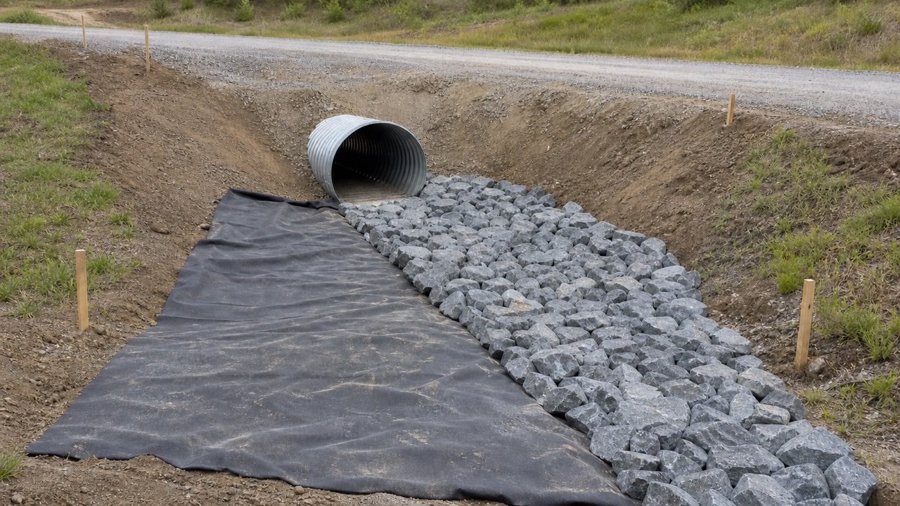
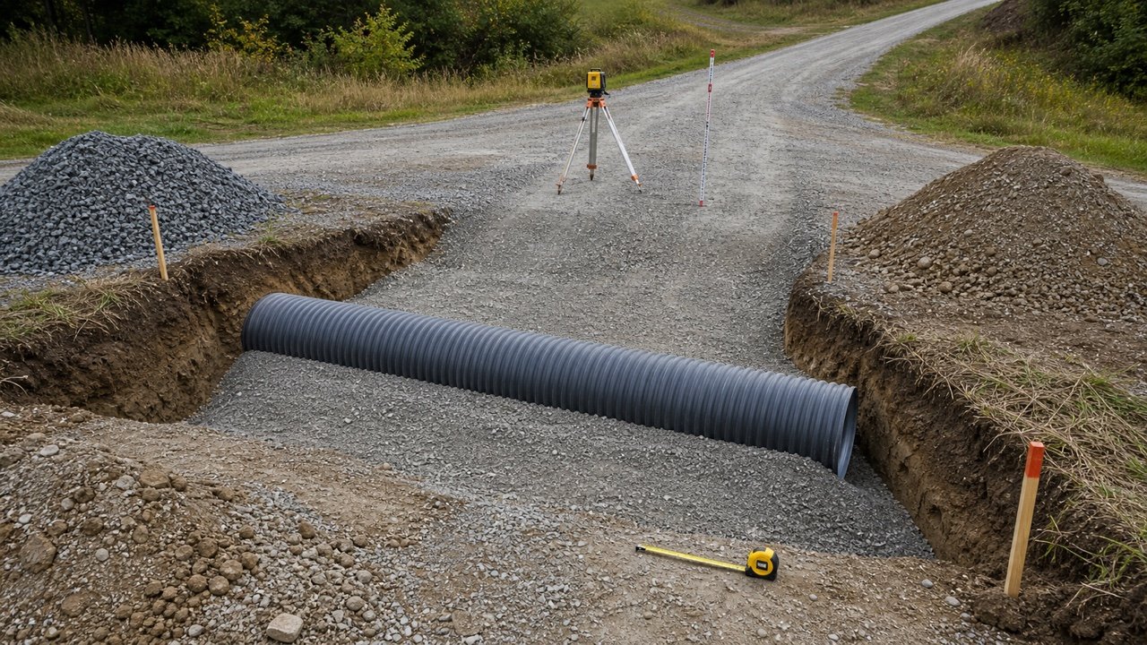
| Culvert or concentrated runoff | Excavation, bedding, cover, headwalls, and erosion protection are separate quantities | Use a designed drainage crossing |
| Variable width or turnout | One length-times-width rectangle misses area | Measure segments or use a surveyed outline |
| Snow plowing or edge drop-off | Surface material and edge confinement affect maintenance loss | Coordinate profile, aggregate, markers, and maintenance method |
Common gravel driveway quantity mistakes
- Selecting a structural depth from a generic table without checking traffic, soil, climate, water, and local practice.
- Using excavation depth as aggregate depth.
- Combining base and surface volume, then ordering one material.
- Forgetting that different layers can have different widths or limits.
- Calling a compacted geometric result a loose delivery quantity.
- Using one universal density for every aggregate source and moisture state.
- Adding a generic waste percentage before identifying what it covers.
- Rounding each layer early instead of summing precise values.
- Ignoring garage, road, gate, drainage, and utility elevations.
- Adding an inch for geotextile when no granular layer has been specified.
- Using full construction depth for a surface top-up.
- Filling recurring ruts without investigating subgrade or drainage.
- Assuming the nominal truck-body capacity proves the delivered volume.
What should the driveway quantity record contain?
- Project location, drawing, specification, revision, and measurement date.
- Measured layer footprints and excluded areas.
- Prepared-surface and target-finish elevations at controlling points.
- Accepted compacted thickness and material specification for each layer.
- Compacted geometric volume before adjustments.
- Loose-to-compacted factor, definition, source, and applicable conditions.
- Bulk density or package yield, product, source, state, and date.
- Separate handling allowance and its evidence.
- Supplier selling unit, rounding increment, minimum order, and delivery constraints.
- Open assumptions, field changes, prepared by, checked by, and approval status.
Safety and scope
Use project drawings, geotechnical recommendations, supplier or manufacturer data, permits, utility information, and applicable local standards. A qualified professional may be needed for weak or variable soils, slopes, retaining conditions, drainage crossings, flood exposure, heavy vehicles, public-road connections, or work near buried services.
This guide checks geometry and quantity records. It does not design a pavement, approve a subgrade, select an aggregate, set a compaction method, size drainage, locate utilities, or certify construction.
Sources and source scope
- FHWA, Geotechnical Aspects of Pavements, Chapter 3: traffic, subgrade, climate, rutting, aggregate loss, durability, and seasonal inputs used in aggregate-surfaced road thickness design.
- USDA NRCS, Access Road Conservation Practice Standard 560: vehicle, load, soil, climate, drainage, surfacing, geotextile, and plan-content considerations within its access-road scope.
- USDA Forest Service Transportation Toolbox: current access point for the Earth and Aggregate Surfacing Design Guide for Low-Volume Roads.
- FHWA Federal Lands, Pavement Design and Development Manual, Chapter 11: established aggregate-surfaced road design procedures and project inputs.
- NIST Guide to the SI, Appendix B.8: exact unit relationships used in the imperial conversion.
Scope: the official road sources show why thickness, drainage, materials, and traffic require project inputs. They do not supply one universal residential-driveway depth or order factor. The worked examples test arithmetic for stated hypothetical cross-sections; they are not design recommendations.
Enter approved base and surface depths in the Driveway Gravel Calculator. For one material at one depth, use the Gravel Calculator. Then compare material options in the gravel size chart, review purchasing steps in the gravel cost guide, or return to the Gravel planning hub.