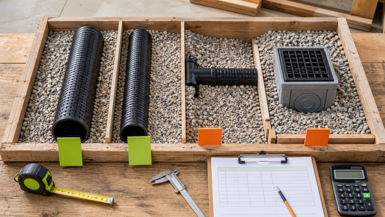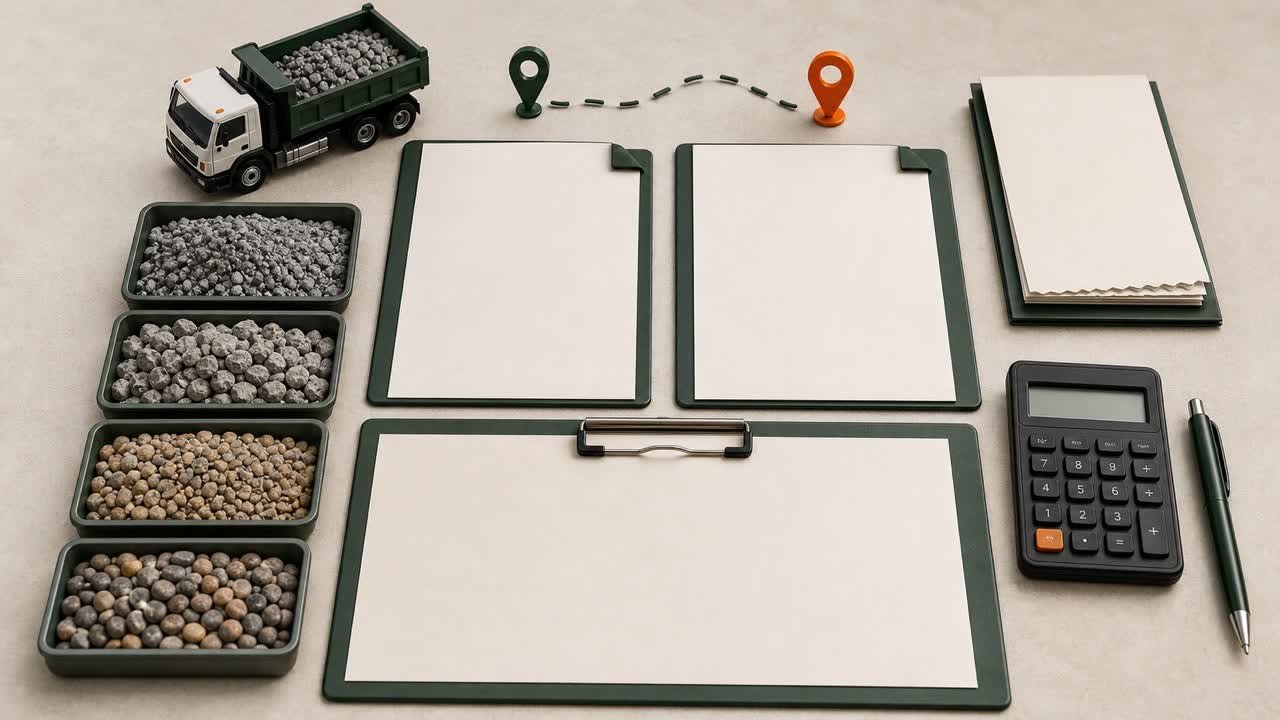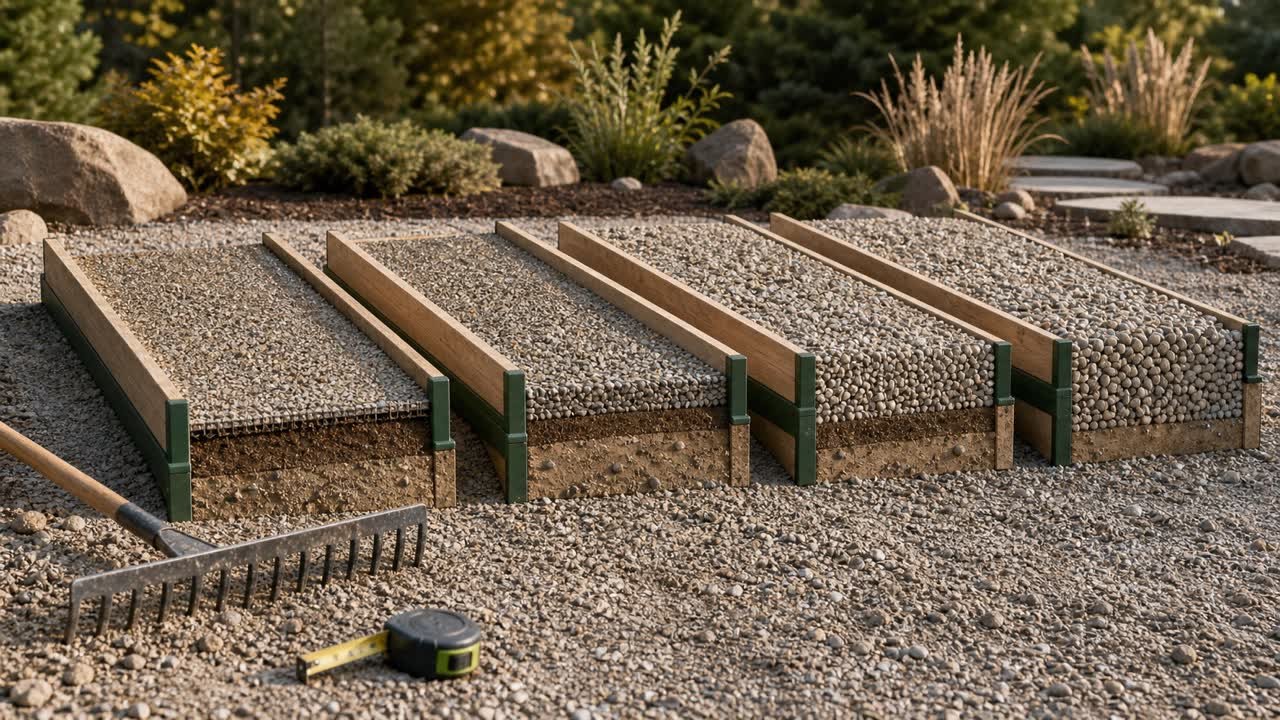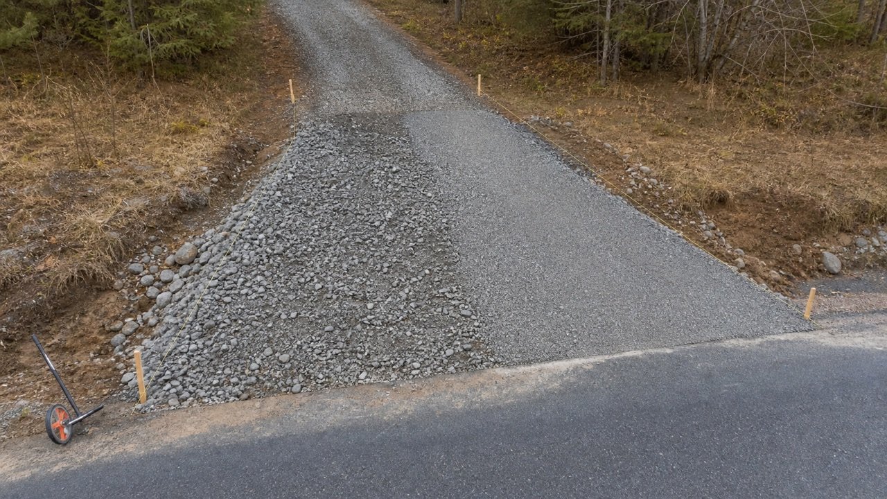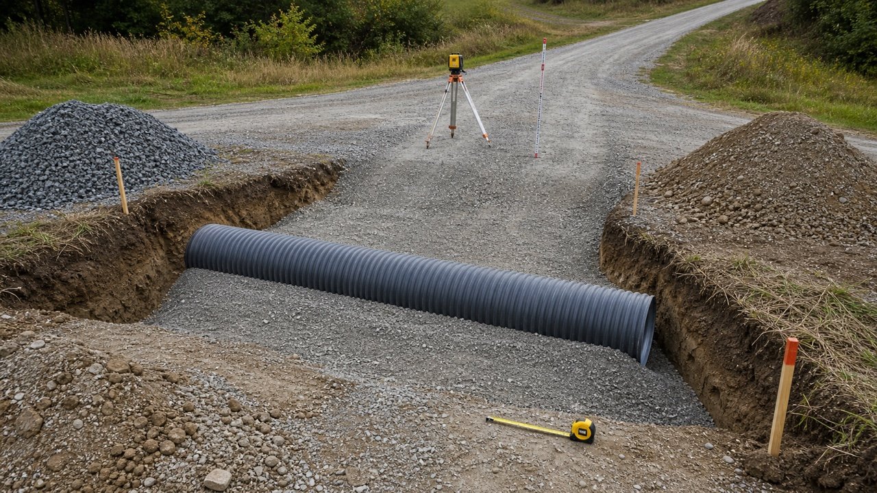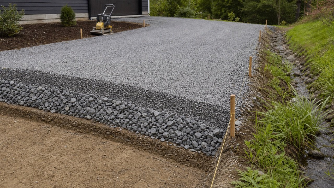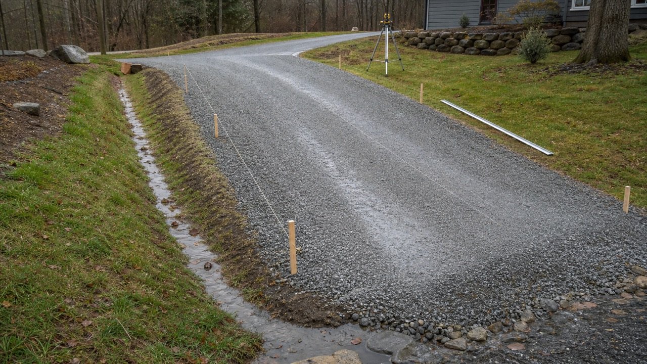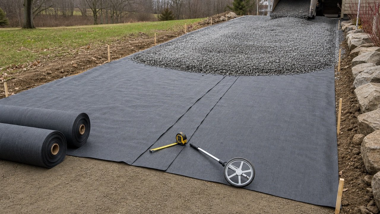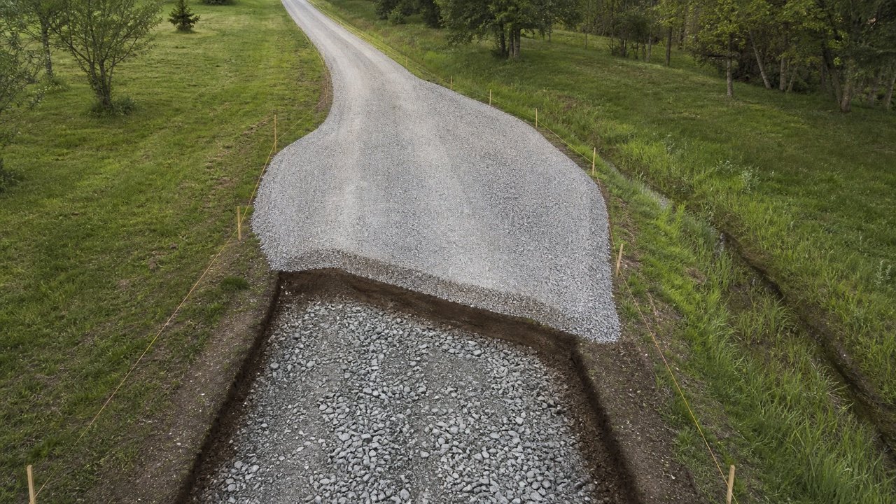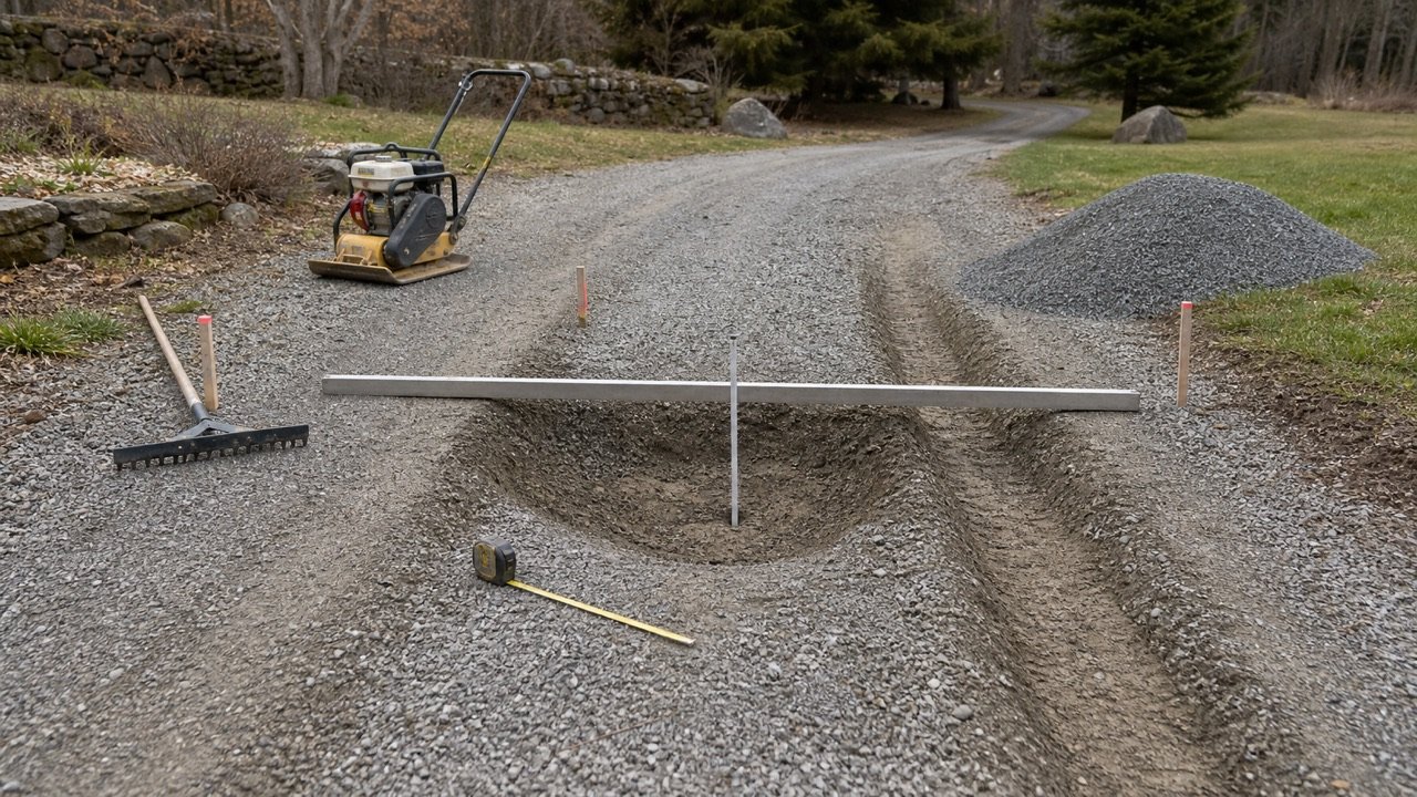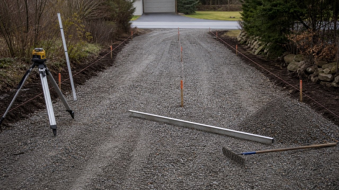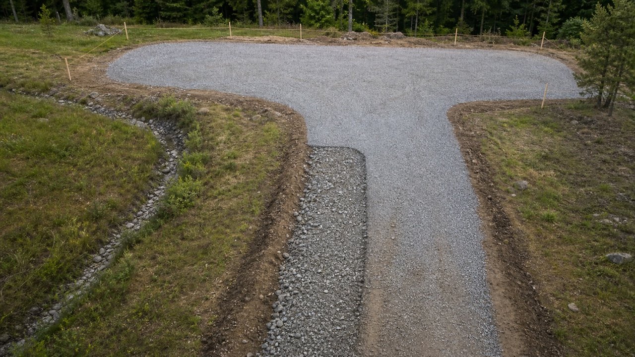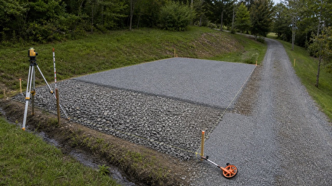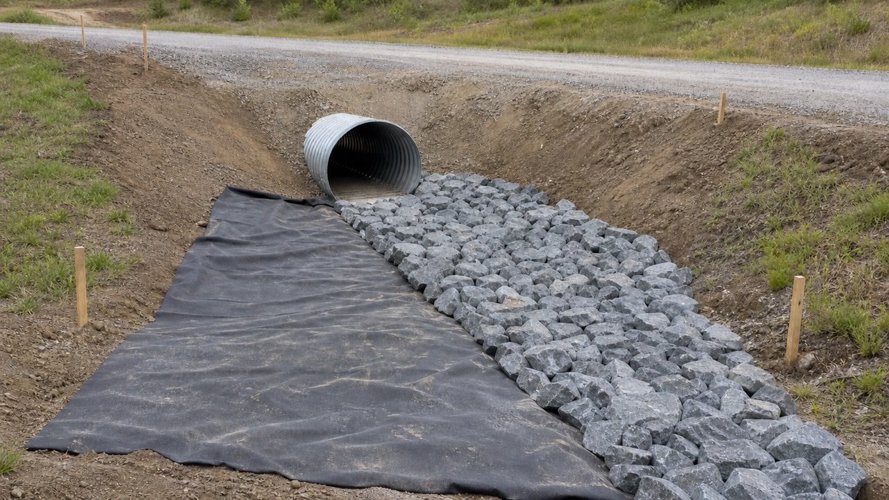
A driveway culvert end-protection takeoff begins with an approved inlet and outlet detail. The drawing or specification must define the protected limits, rock class, layer thickness, filter or geotextile, toe treatment, end section, and measurement rules.
Measure the inlet and outlet as separate locations. Their slopes, widths, structures, rock classes, and filter details can differ even when they serve the same pipe.
How do you calculate riprap and geotextile for a culvert end?
Measure the approved apron surface, multiply it by the specified riprap thickness, then add non-overlapping toe, cutoff, side-slope, or end-return zones. Measure geotextile along the surface it covers and add only the specified returns, anchors, seams, and overlaps.
Slope length = √(horizontal length² + vertical fall²)
Flared apron surface area = slope length × (start width + end width) ÷ 2
Placed riprap volume = applicable apron area × approved layer thickness
Total rock = apron rock + separate toe, key, or return rock
Record whether thickness is measured normal to the slope or vertically. That direction controls which area belongs in the volume formula.
This method measures an approved end treatment. It does not select the culvert, design flow, apron dimensions, rock class, thickness, filter, scour depth, channel transition, or maintenance requirement.
Which approved details are needed before measuring?
Use the latest plan, sections, hydraulic notes, standard-detail references, specification, permit, and material schedule. Resolve missing dimensions or conflicting revisions before turning geometry into an order.
FHWA Federal Lands Highway guidance says outlet-protection plans should show the location, riprap dimensions and extent, gradation, bedding or geotextile, and grading or slope details. Those fields form the minimum quantity basis.
| Input | Record | Quantity effect |
|---|---|---|
| Location | Crossing ID, inlet or outlet, station, side, and flow direction | Prevents 2 ends from being combined under one assumed shape |
| Protected limits | Apron start, end, widths, side-slope returns, and tie-in boundary | Defines the rock and filter footprint |
| Surface levels | Start, end, break points, and cross-slope elevations | Changes slope length and surface area |
| Riprap | Named class, gradation, thickness, placement method, and thickness direction | Controls each placed-rock zone |
| Filter | Geotextile or granular filter product, limits, seams, overlaps, returns, and anchors | Controls surface area, panels, rolls, and separate granular volume |
| End structure | Pipe end, flared section, headwall, wingwall, apron slab, and footing | Creates exclusions, interfaces, and separate structure quantities |
| Toe or cutoff | Location, length, section, and whether it overlaps the apron layer | Adds a separate rock or excavation zone without double counting |
| Supplier basis | Product, material state, density, selling unit, increment, quote date, and delivery limit | Converts geometric volume into the purchase quantity |
The FHWA W251-1 standard drawing shows why scope matters. It pairs apron geometry with estimated riprap and geotextile quantities and states limits for that detail. Its table can check a project that adopts it, but its dimensions should not be copied into an unrelated driveway design.
How is a flared apron area measured?
Use trapezoidal area where the apron changes from one width to another at a steady rate. Measure length along the surface when the quantity covers a sloping surface.
Trapezoid area = measured length × average width
Average width = (start width + end width) ÷ 2
A plan view gives horizontal length and widths. A section gives vertical fall. Combine the horizontal length and fall with the Pythagorean formula to find straight slope length. Add a station wherever the slope or width changes.
| Shape | Method | Use when |
|---|---|---|
| Rectangle | Length × width | Width stays constant |
| Trapezoid | Length × (start width + end width) ÷ 2 | Width changes at a steady rate |
| Triangle | Base × height ÷ 2 | A side flare or corner closes to a point |
| Station segments | Sum each short rectangle or trapezoid | Width, grade, or cross-slope changes along the apron |
| Survey or CAD boundary | Checked surface or polygon area | The edge curves, wraps a structure, or follows irregular ground |
Use surface area for fabric laid on a slope. A horizontal plan area understates fabric where the vertical change is material. Stepped sections, compound slopes, or a curved ditch need measured panels or a checked surface model.
Does riprap thickness run vertically or normal to the slope?
The project detail must state the thickness convention. A thickness measured normal to the slope uses sloped surface area; a vertical thickness uses horizontal plan area.
| Drawing basis | Area used | Volume check |
|---|---|---|
| Thickness normal to surface | Sloped surface area | Surface area × normal thickness |
| Vertical thickness between elevations | Horizontal plan area | Plan area × vertical thickness |
| Variable section | Cross-sectional or model quantity | End-area, prismoidal, station, or checked design-model method |
Do not choose the convention from a sketch that lacks a dimension arrow. Send the unresolved point to the designer or approving authority. The difference grows with slope and can affect both the rock volume and excavation limits.
Worked imperial example
An approved outlet apron has a 10 ft horizontal length and a 2 ft fall. Its width changes from 6 ft at the pipe to 12 ft at the downstream end. Riprap is 1.5 ft thick normal to the surface. A 12 ft × 2 ft × 2 ft toe trench lies beyond the apron, so it does not overlap the apron layer.
| Quantity | Calculation | Result |
|---|---|---|
| Slope length | √(10² + 2²) | 10.198039 ft |
| Apron surface | 10.198039 × (6 + 12) ÷ 2 | 91.782351 ft² |
| Base geotextile | 91.782351 ÷ 9 | 10.198039 yd² before returns and overlaps |
| Apron riprap | 91.782351 × 1.5 | 137.673527 ft³ = 5.099020 yd³ |
| Toe-trench riprap | 12 × 2 × 2 | 48 ft³ = 1.777778 yd³ |
| Total placed rock | 137.673527 + 48 | 185.673527 ft³ = 6.876797 yd³ |
The base geotextile value excludes side returns, the toe wrap, anchors, and seams because their dimensions were not supplied. The placed-rock total also excludes supplier conversion and handling allowance.
Worked metric example
A second approved apron is 3.5 m long horizontally and drops 0.6 m. The width changes from 1.8 m to 3.6 m. Riprap thickness is 0.45 m normal to the surface. A 3.6 m × 0.6 m × 0.8 m toe trench sits outside the apron.
| Quantity | Calculation | Result |
|---|---|---|
| Slope length | √(3.5² + 0.6²) | 3.551056 m |
| Apron surface | 3.551056 × (1.8 + 3.6) ÷ 2 | 9.587852 m² |
| Apron riprap | 9.587852 × 0.45 | 4.314533 m³ |
| Toe-trench riprap | 3.6 × 0.6 × 0.8 | 1.728000 m³ |
| Total placed rock | 4.314533 + 1.728000 | 6.042533 m³ |
The horizontal plan area is 9.450000 m². A 0.45 m vertical thickness would give 4.252500 m³ for the apron, so the quantity record must preserve the normal-to-slope instruction used here.
Which areas should be excluded from the apron?
Subtract a structure footprint only where the measurement rule excludes it from the rock or filter zone. Use the actual intersection with that zone rather than the full object size.
- A pipe opening can interrupt fabric or rock near the end face, but the deduction depends on the detail and installed contact surface.
- A flared end section can sit above, within, or beyond an apron. Record its overlap from plan and section views.
- A headwall, wingwall, footing, concrete apron, or cutoff wall occupies only its measured intersection with the riprap zone.
- Existing stable protection reduces new work only where the project accepts it to remain.
- A void under a cantilevered outlet, plunge pool, or drop needs a designed section. A flat-plan deduction cannot describe it.
Label every exclusion in the worksheet. A single unexplained net area is hard to check when a structure or field limit changes.
How are toe trenches, keys and side returns kept separate?
Draw each zone once and mark its boundary against the main apron. Add the full toe or key only when it lies outside the apron volume; add only its extra section where the 2 shapes overlap.
Example: a toe trench begins at the apron end and extends beyond it. Its full section can be a separate line. If the trench is cut through the last 2 ft of the apron, subtract the apron layer already counted within that footprint before adding the deeper trench section.
| Zone | Measure | Double-count check |
|---|---|---|
| Main apron | Approved surface or plan area × thickness basis | Stop at the recorded boundary |
| Toe trench | Net trench section × length | Remove any apron layer already included inside it |
| Side-slope return | Separate slope surface × thickness | Join at a line rather than overlapping surfaces |
| Pipe-end collar | Approved ring, block, or model geometry | Deduct pipe or structure void once |
| Granular filter | Filter surface × approved depth | Keep it outside riprap and geotextile units |
| Placement excavation | Approved excavation envelope | Check the contract measurement rule before treating it as a paid item |
The FHWA W251-1 drawing includes a note that placement excavation is not measured for payment under that standard. A private driveway estimate may still need labor and excavation quantities. Keep construction cost, physical quantity, and contract pay measurement as separate fields.
How is geotextile converted from surface area to rolls?
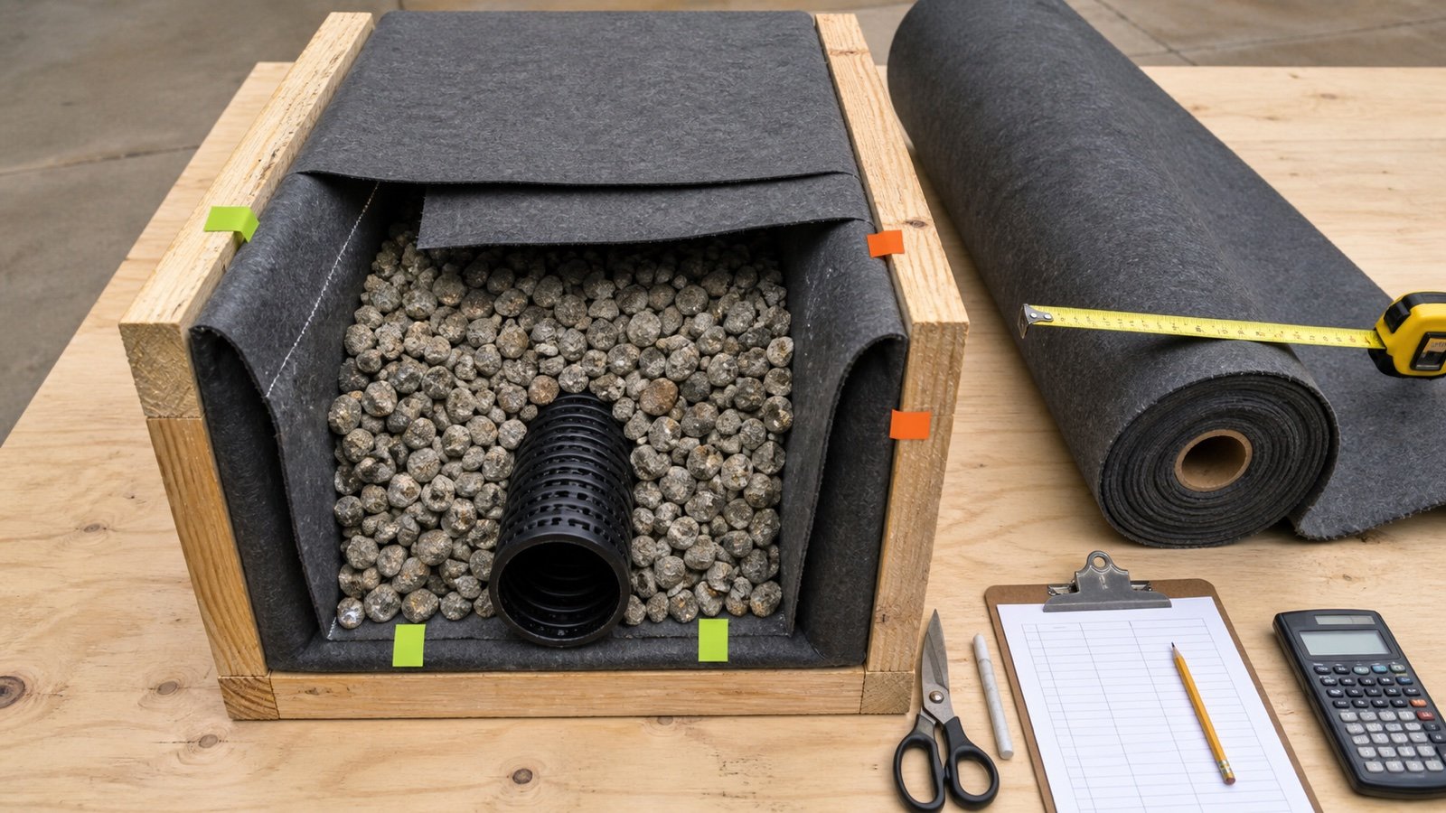
Start with the net surface that the specified fabric covers. Create a panel layout using the selected product's roll width, roll length, permitted orientation, overlaps, seams, returns, and anchorage detail.
- Measure the apron, side returns, toe wrap, and anchor zones along their surfaces.
- Subtract only openings or structures where the detail stops the fabric.
- Lay out full-width panels in the permitted direction.
- Add specified longitudinal and transverse overlaps by seam count and seam length.
- Add end returns, key trenches, and anchors as measured strips or panels.
- Check cuts around pipe ends, headwalls, and changes in slope.
- Round the final panel schedule to whole rolls or the supplier's selling increment.
Area plus a percentage does not prove that available rolls can cover a tapered apron. A panel schedule exposes narrow offcuts, cross seams, and a final strip that may require another roll. The geotextile area and roll guide gives the full panel method.
What can the Gravel Calculator check for this takeoff?
Use the Gravel Calculator after the approved geometry has been reduced to one uniform area and one thickness. Use known-area mode for a separately measured apron surface, toe section, or side return. Keep every non-overlapping zone and rock class in a separate calculation.
| Quantity zone | Calculator entry | Keep outside the calculator |
|---|---|---|
| Main apron with thickness normal to slope | Measured sloped surface area in known-area mode, plus normal thickness | How the apron dimensions, slope, and rock class were approved |
| Main apron with vertical thickness | Horizontal plan area in known-area mode, plus vertical thickness | The drawing note that defines vertical thickness |
| Toe trench, key, or side return | A separate known area or uniform rectangular zone and its applicable thickness | Overlap deductions and irregular cross-sections |
| Geotextile | No rock-volume entry | Surface panels, seams, overlaps, returns, anchors, offcuts, and whole rolls |
| Supplier mass | Optional product-specific bulk density in the matching material state | Selling unit, minimum order, delivery increment, legal payload, and quote terms |
| Hydraulic protection design | No entry | Flow, tailwater, scour, apron dimensions, rock class, filter, and maintenance design |
Add unrounded volume results only after checking that the zones do not overlap. The calculator does not size the protection, combine irregular surfaces, or convert geotextile area into rolls.
How is placed rock converted to a supplier order?
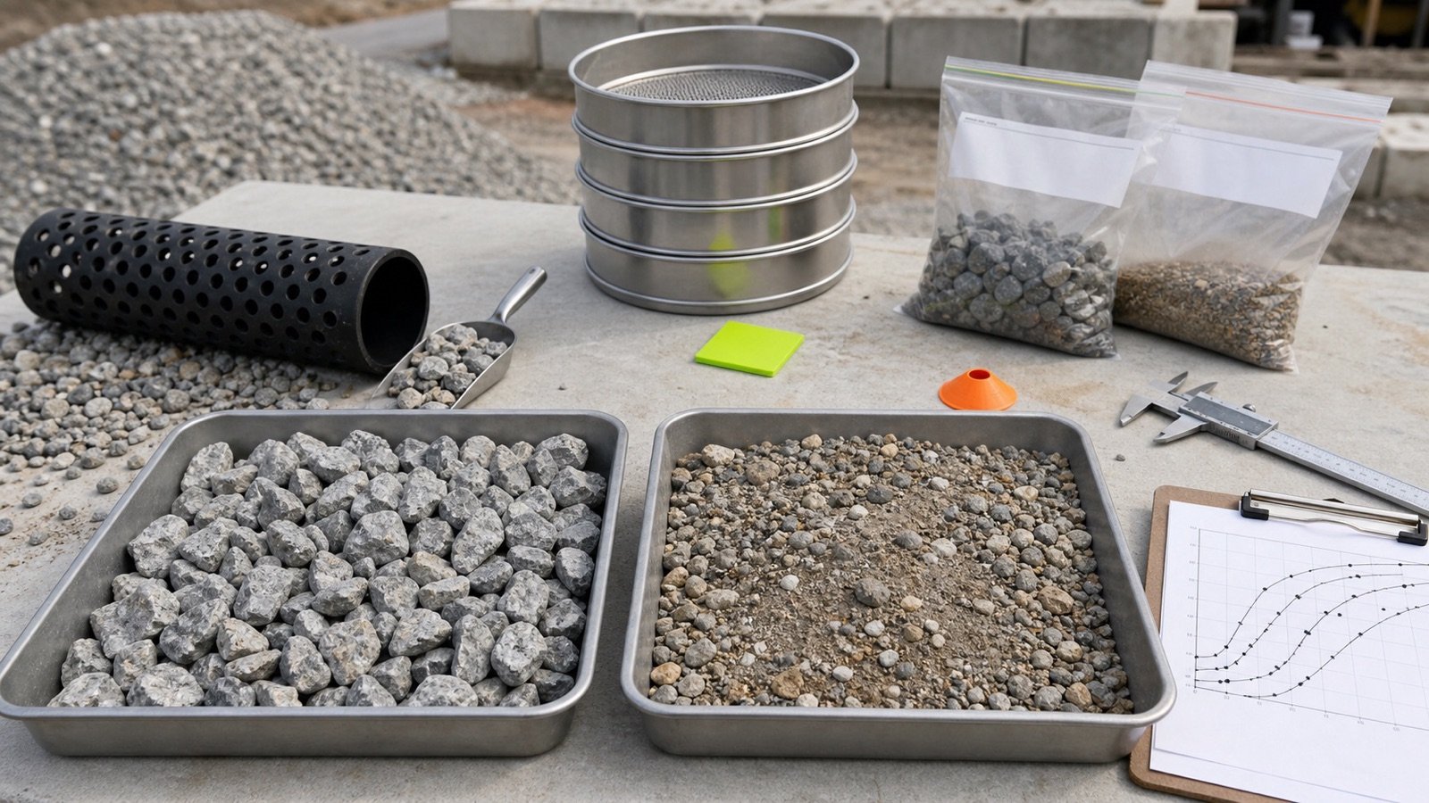
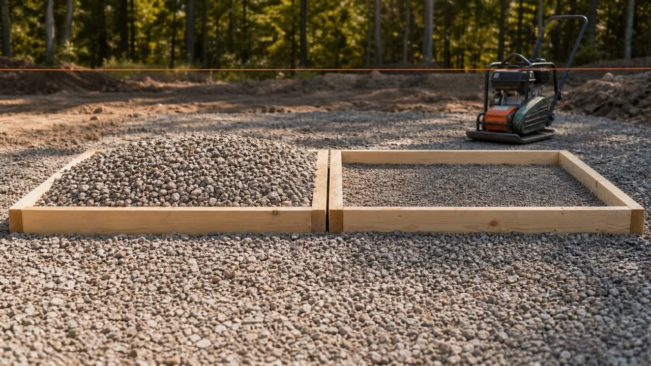
Use the placed geometric volume as the starting line. Apply a density or loose-volume relationship that belongs to the selected product and stated material condition.
Ordered mass = placed volume × documented placed bulk density
- Sum each approved rock class without early rounding.
- Confirm whether the supplier sells by mass or loose volume.
- Use the quarry, supplier, project test, or specification density that matches the quantity state.
- Add a separate handling allowance only when field records or the delivery method supports it.
- Round once to the selling increment.
- Confirm legal payload, access, unloading area, minimum load, fees, and quote expiry.
Particle density or specific gravity cannot replace bulk density in an order calculation because voids between stones remain in the placed material. A truck-body label also does not prove delivered mass or placed volume.
Use the gravel weight chart to review density scope, then follow the volume-to-order workflow. Keep each rock class and material state on its own line.
Which conditions need a new design decision?
Pause the quantity takeoff when the site no longer matches the approved detail. Quantity arithmetic cannot resolve a hydraulic, structural, environmental, or right-of-way conflict.
| Condition | Quantity effect | Required decision |
|---|---|---|
| Outlet scour or displaced rock | Existing limits and foundation levels may have changed | Inspect and revise the repair detail before measuring replacement material |
| Steep outlet or drop | A flat or mild-slope apron geometry may be unsuitable | Use the treatment selected by the hydraulic designer |
| High velocity, tailwater, debris, or ice | Rock class, apron form, and maintenance can change | Complete the required hydraulic and site assessment |
| Multiple pipes or box culvert | Openings, transitions, and flow distribution change the end geometry | Use the approved multi-cell detail or model |
| Public ditch, stream, wetland, or property boundary | Permitted limits and materials may control the footprint | Obtain the authority and environmental approvals |
| Buried services or unstable excavation | Excavation, access, and temporary works can change | Locate services and apply the required safety system |
FHWA HEC-14 covers outlet velocity, scour, tailwater, and energy-dissipation design. Use that work through a qualified designer rather than treating the quantity formulas as an apron-sizing method.
Common quantity mistakes
- Choosing apron length, width, thickness, or rock class from a generic web table.
- Combining the inlet and outlet under one assumed shape.
- Using horizontal plan area for fabric installed along a slope.
- Using slope area with a thickness defined vertically, or plan area with a thickness defined normal to slope.
- Measuring the full maximum thickness across a variable section.
- Subtracting the full pipe or headwall footprint when only part intersects the measured zone.
- Adding a toe trench after its full depth was already included in the apron section.
- Counting the same rock where the apron and side-slope return overlap.
- Applying one percentage to represent fabric seams, cuts, anchors, and whole-roll rounding.
- Using particle density, a generic tons-per-yard value, or nominal truck capacity.
- Combining placed geometry, loose delivery volume, mass, and pay quantity.
- Rounding each small shape before the inlet or outlet total is complete.
What should the field quantity record contain?
- Project, crossing ID, inlet or outlet, location, date, weather, and flow condition.
- Drawing, detail, specification, permit, revision, and open clarification.
- Survey datum, start and end points, widths, levels, slope breaks, and measured surfaces.
- Rock class, thickness, thickness direction, filter, geotextile product, and installation limits.
- Gross shapes, exclusions, toe or key zones, and double-counting checks.
- Geotextile panels, seams, overlaps, returns, anchor strips, roll size, and offcuts.
- Placed rock volume, density source and state, order mass or volume, handling line, and supplier increment.
- Quote date, delivery basis, legal payload check, access, unloading area, and minimum load.
- Measured by, checked by, outstanding design decisions, inspection notes, and photographs.
Safety and scope
Locate buried services, assess water and ground conditions, control traffic where required, and keep workers and equipment clear of unstable banks and pipe ends. OSHA trenching and excavation guidance identifies cave-ins and other excavation hazards for US workplaces. Follow the rules that apply to the project and the competent person's directions.
This guide checks geometric and supplier quantities. It does not approve work in a public ditch or watercourse, size a culvert, establish scour protection, design a headwall, select a geotextile, or certify the completed end treatment.
Sources and source scope
- FHWA Office of Federal Lands Highway, Standard W251-1: example of an approved standard that records apron geometry, rock class, estimated riprap quantity, geotextile quantity, end-section condition, and applicability notes.
- FHWA, Notes to the Designer for C251-50: stated slope and measurement limits for that standard detail. The notes were shown as updated March 2026 when checked on 2026-07-31.
- FHWA Federal Lands Highway, PDDM Chapter 7: design-documentation requirements for dimensions, extent, gradation, bedding or geotextile, grading, and slope details.
- FHWA HEC-14: hydraulic-design context for outlet velocity, scour, tailwater, filter protection, and energy dissipation.
- NIST Guide to the SI, Appendix B.8: exact unit relationships used in the worked examples.
- OSHA, Trenching and Excavation: US workplace excavation-hazard scope.
Source scope: the FHWA standard drawing illustrates one approved system and cannot set universal driveway dimensions. HEC-14 and the PDDM establish the design boundary. The worked examples test quantity arithmetic for stated hypothetical approved layouts.
Start with the driveway culvert bedding and backfill guide, check fabric rolls with the geotextile takeoff guide, calculate a uniform approved rock zone with the Gravel Calculator, or return to the Gravel planning hub.