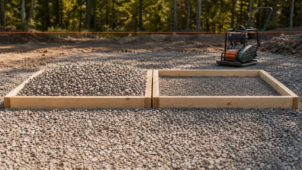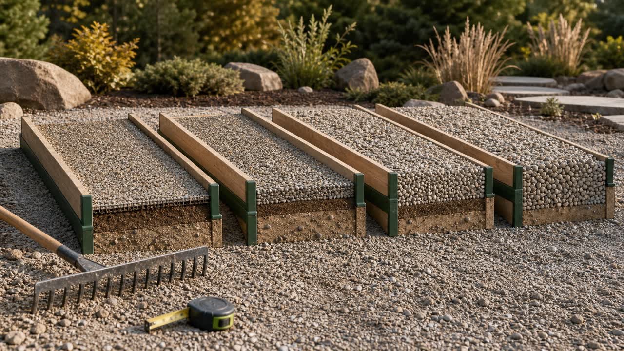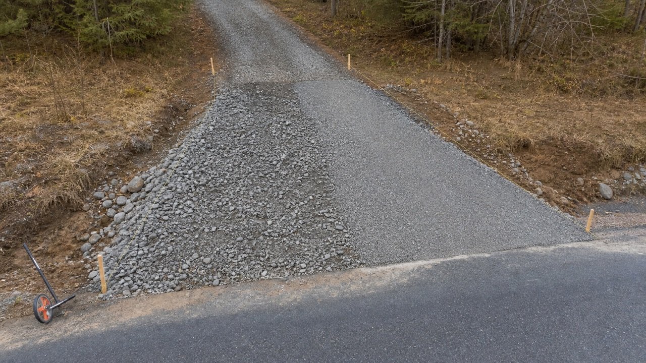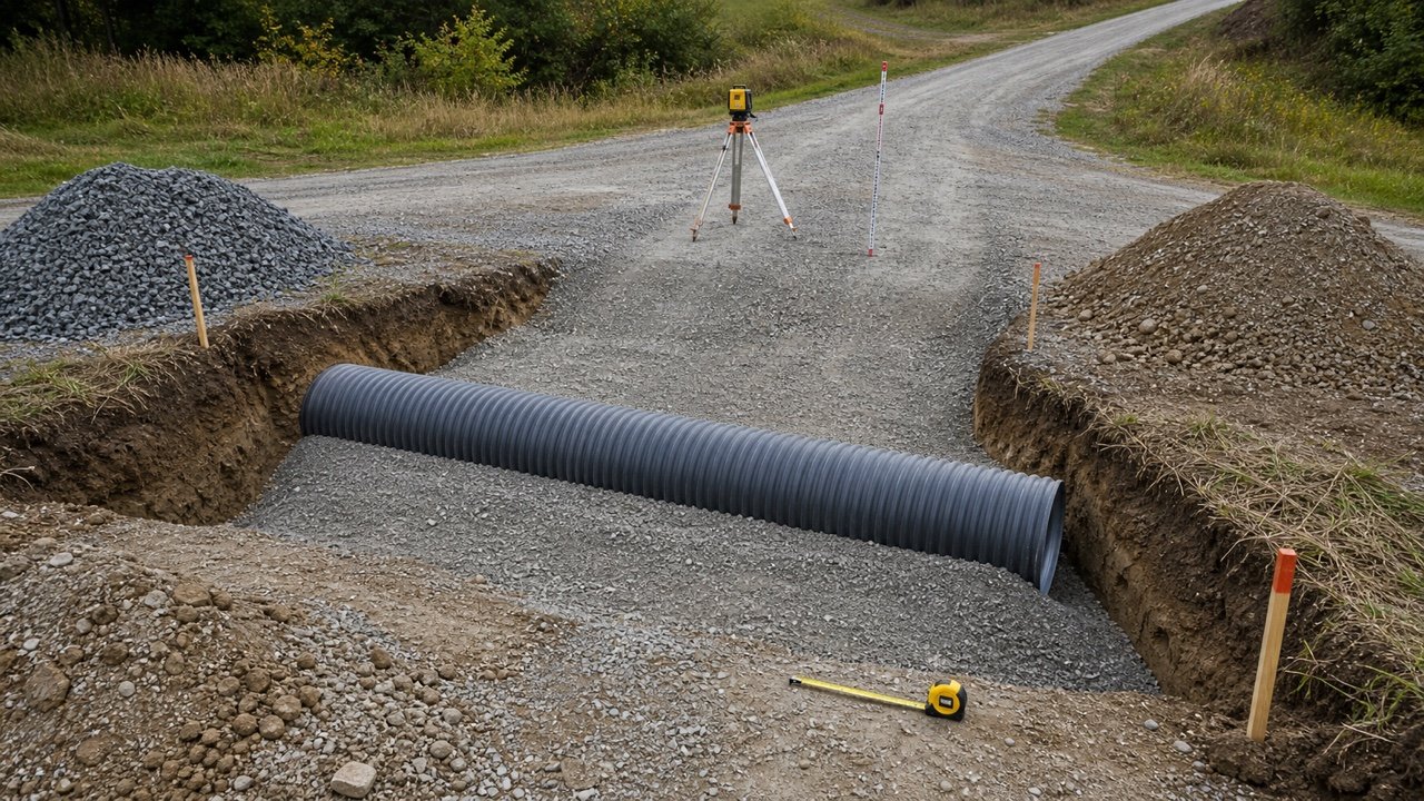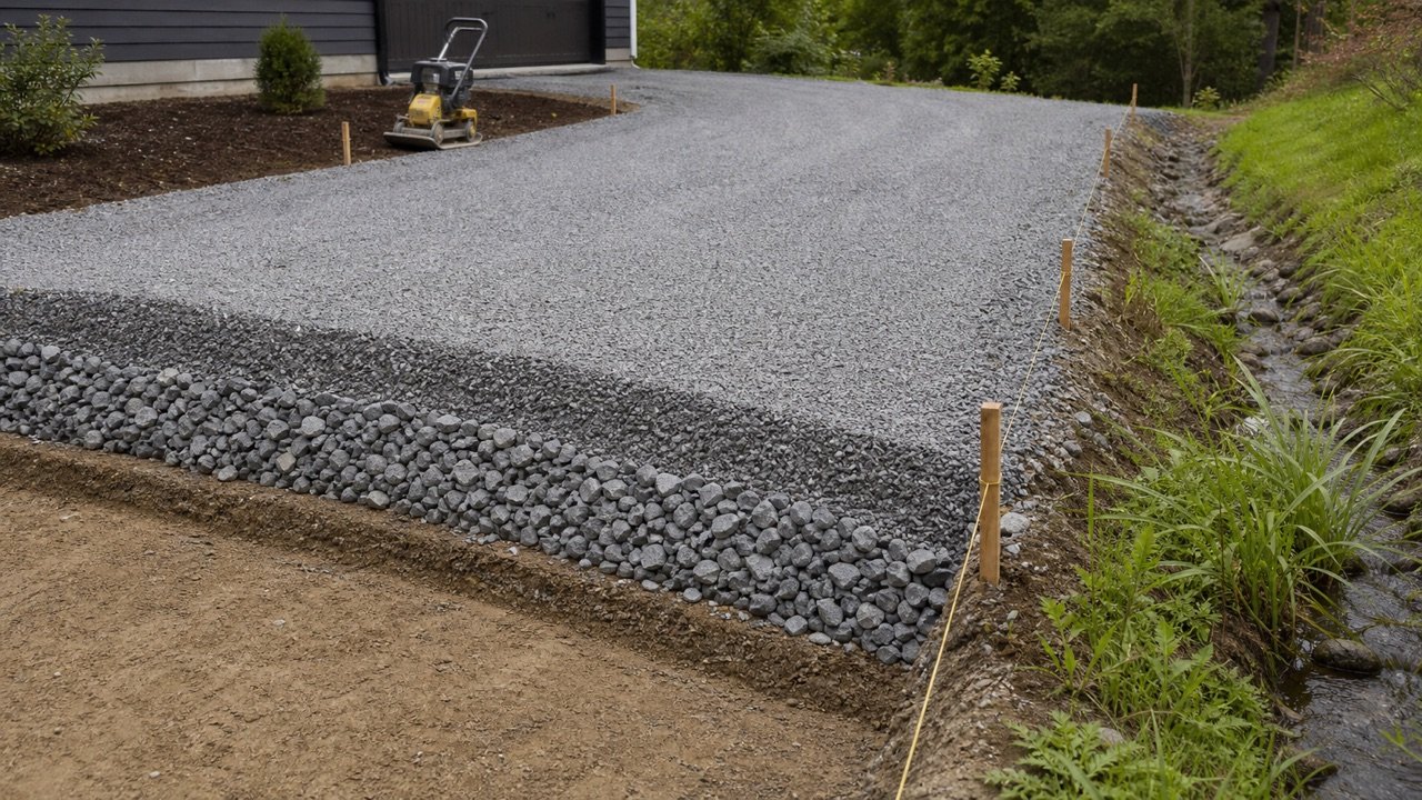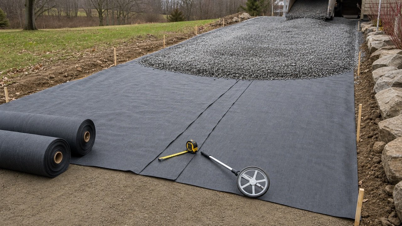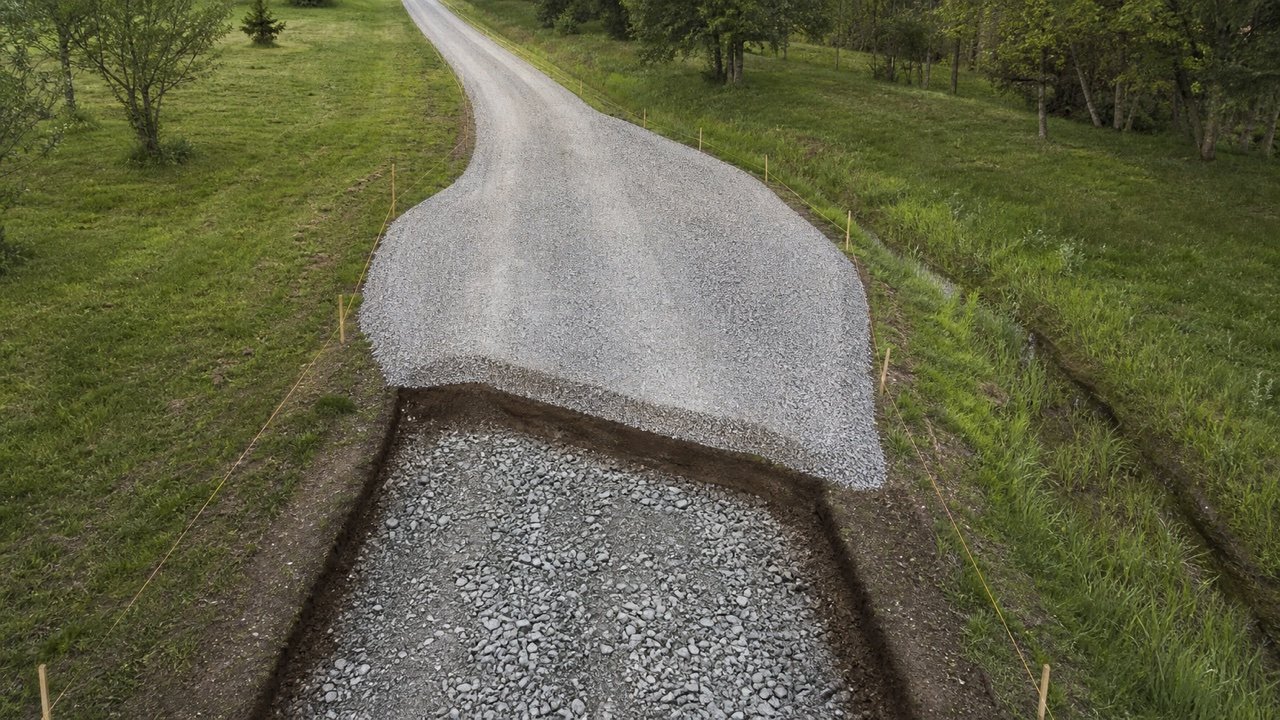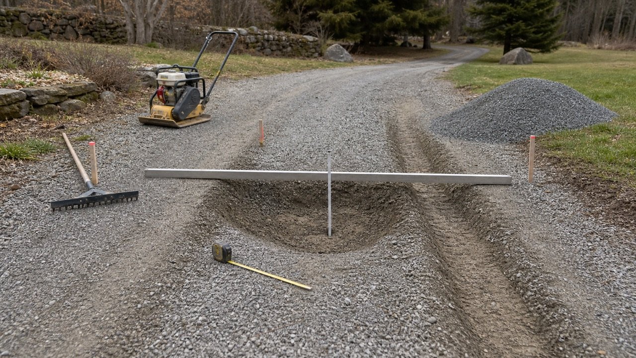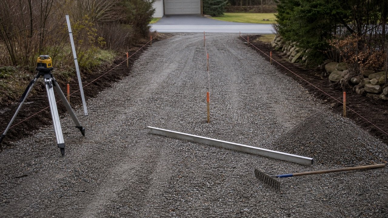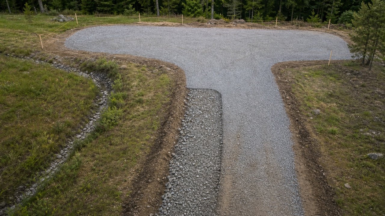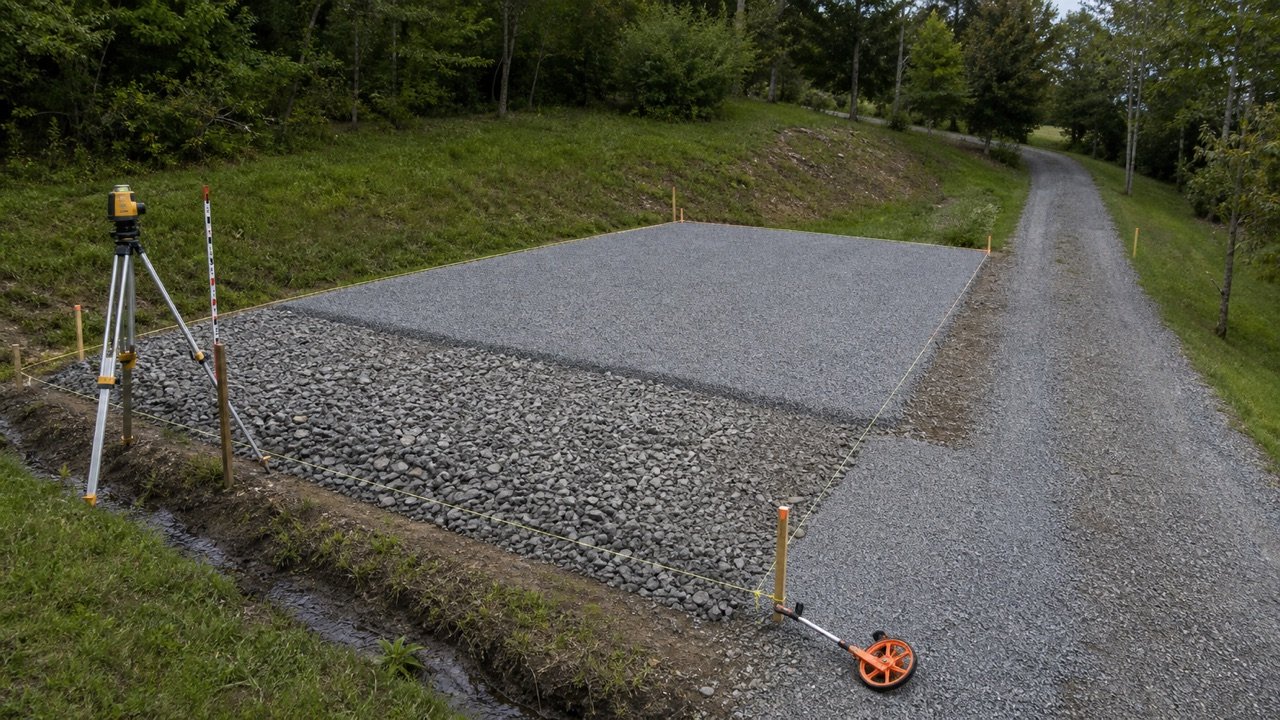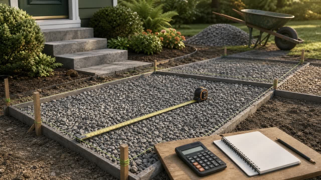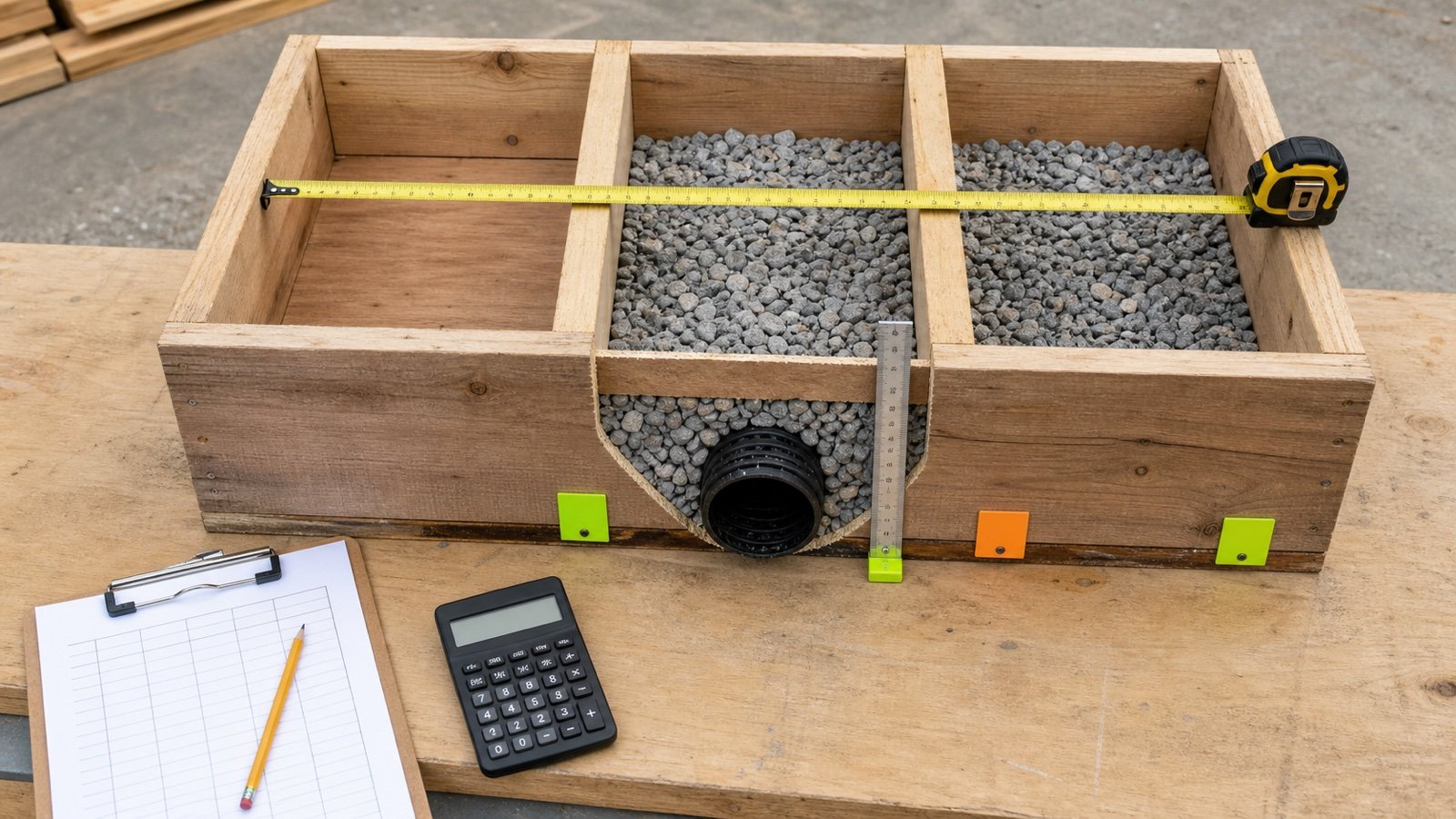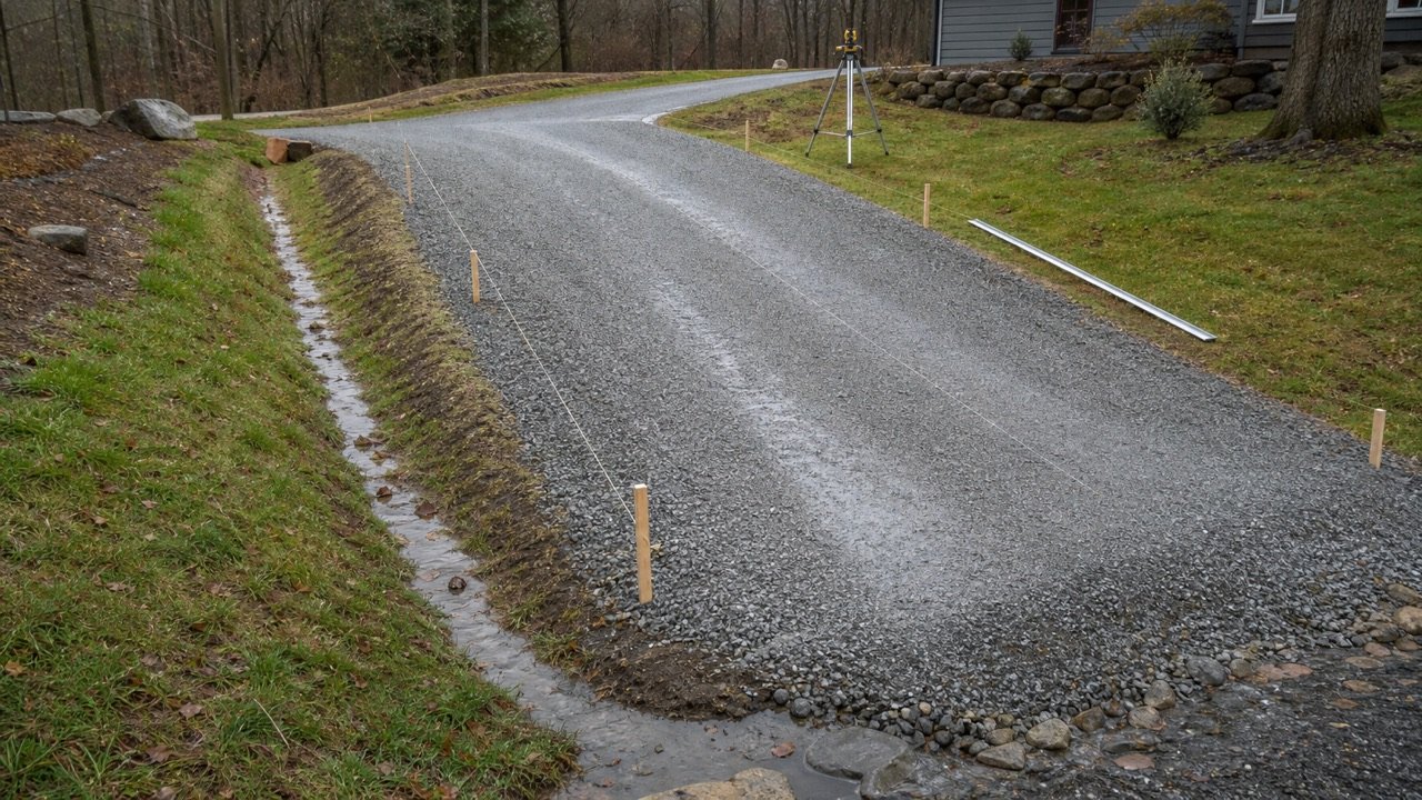
Water must leave a gravel driveway surface and reach a suitable outlet. Check the side-to-side crossfall, the lengthwise grade, and the elevations along both edges before adding gravel or cutting a drain.
A percentage alone cannot confirm drainage. A driveway can meet an average grade and still contain a low spot, reverse fall, blocked edge, or outlet that cannot accept the runoff.
How should gravel driveway drainage be checked?
Establish one elevation datum, measure the center and both edges at regular stations, calculate the fall between each pair of points, and trace each low path to an approved outlet. Use the crossfall or crown required by the project and local conditions.
Official road documents use different values because their scopes differ. FHWA Federal Lands normally uses a 4% crown cross slope for gravel-surfaced roads in its highway-design context. USDA NRCS gives a 2% to 6% range for unpaved access roads in its national conservation standard. A Vermont lakeshore BMP uses 1/2 in per foot from the centerline to the edge for its camp-road erosion-control work.
These agency values describe particular road programs. The project designer, local authority, site drainage, traffic, surface material, climate, accessibility needs, road connection, and outlet conditions control a residential driveway.
This guide checks measured geometry and quantities. It does not size a ditch, culvert, channel drain, infiltration system, or pipe.
Which driveway slope are you measuring?
Crossfall moves water across the driveway. Longitudinal grade describes the rise or fall along its length. A crown has 2 crossfalls that start at a high centerline and descend toward opposite edges.
| Term | Points compared | Use |
|---|---|---|
| One-way crossfall | High edge to low edge across the full width | Checks side-to-side drainage in one direction |
| Crown crossfall | Centerline to each edge, calculated as 2 separate half-widths | Checks drainage from the center toward both sides |
| Longitudinal grade | 2 stations along the centerline or the same edge | Checks lengthwise fall and identifies sags or crests |
| Outlet grade | Inlet, channel, ditch, pipe, or discharge elevations | Checks continuity after water leaves the driveway surface |
| Drainage gradient | The steepest fall on a surface affected by both crossfall and longitudinal grade | Requires the full surface geometry; one percentage may not describe its direction |
Keep the measurement lines separate. A centerline can descend while one edge rises into a local dam. A crown can also lean when the left and right edges have different elevations.
How do you calculate fall and slope?
Subtract the low elevation from the high elevation to find fall. Divide that fall by the horizontal run, then multiply by 100 for percent slope.
Fall = high elevation - low elevation
Slope (%) = fall ÷ horizontal run × 100
Required fall = horizontal run × slope (%) ÷ 100
Use the same units for fall and run. A 0.12 ft fall over 6 ft is `0.12 ÷ 6 × 100 = 2%`. Convert the result after completing the division.
| Format | Formula | 4% example |
|---|---|---|
| Percent | Fall ÷ run × 100 | 4% |
| Decimal | Percent ÷ 100 | 0.04 |
| Inches per foot | Percent × 0.12 | 0.48 in/ft |
| Millimetres per metre | Percent × 10 | 40 mm/m |
| Ratio | 1 : run ÷ fall | 1:25 |
| Degrees | arctangent(fall ÷ run) | 2.29061° |
Percent and degrees are different slope formats. A 4% slope is about 2.29°, not 4°. A ratio also needs its direction stated; this page writes `1 vertical : X horizontal`.
Worked imperial crown example
A project specifies a symmetrical 4% crossfall from the centerline to each edge of a 12 ft-wide driveway. The run for each side is half the driveway width.
| Step | Calculation | Result |
|---|---|---|
| Half-width run | 12 ÷ 2 | 6 ft |
| Crown rise | 6 × 4 ÷ 100 | 0.24 ft |
| Convert rise | 0.24 × 12 | 2.88 in |
| Independent check | 2.88 in ÷ 72 in × 100 | 4% |
Do the left and right calculations separately when the edge elevations differ. Setting the center 2.88 in above one edge does not prove the other side has the same fall.
Worked metric one-way crossfall example
A 3.6 m-wide driveway has a project-defined one-way crossfall of 3%. The surveyed high-edge elevation is 54.420 m.
- Calculate the required fall: 3.6 × 3 ÷ 100 = 0.108 m.
- Convert the fall: 0.108 m × 1,000 = 108 mm.
- Calculate the low-edge elevation: 54.420 - 0.108 = 54.312 m.
- Check the slope: 0.108 ÷ 3.6 × 100 = 3%.
The example checks geometry for a stated 3% project value. It does not recommend 3% for another driveway.
How do you check longitudinal grade?
Measure elevations along the same line and divide the fall by the horizontal distance between stations. Check the centerline and both edges because their low points may occur in different places.
Example: the centerline elevation falls from 102.36 ft to 100.92 ft over an 80 ft horizontal run.
- Fall: 102.36 - 100.92 = 1.44 ft.
- Grade: 1.44 ÷ 80 × 100 = 1.80%.
- Fall per foot: 1.80 × 0.12 = 0.216 in/ft.
- Independent check: 80 × 0.018 = 1.44 ft.
An end-to-end calculation can hide a sag between the 2 endpoints. Add stations at grade changes, curves, entrances, ruts, culverts, garage thresholds, and visible wet areas.
How should driveway elevations be recorded?
Use one checked benchmark and record center, left-edge, and right-edge elevations at each station. A laser level, optical level, total station, or another suitable method can establish the differences.
- Mark stations at a spacing that represents the surface and add points at every visible grade break.
- Record the date, instrument, benchmark, datum, rod or target method, and person taking the readings.
- Measure the centerline and both edges without changing the datum.
- Calculate left and right crossfalls at each station.
- Calculate longitudinal grades between consecutive stations along all 3 lines.
- Mark the direction of fall and the receiving edge feature.
- Trace the ditch, swale, channel, culvert, or other route to its outlet.
- Repeat critical readings after grading and compaction.
| Station | Left edge | Center | Right edge | Flow check |
|---|---|---|---|---|
| 0 ft | 99.96 ft | 100.20 ft | 99.96 ft | Both sides fall from center |
| 20 ft | 99.20 ft | 99.90 ft | 99.66 ft | Left edge needs an outlet-level check |
| 40 ft | 99.36 ft | 99.60 ft | 99.36 ft | Left edge rises from station 20 to 40 |
The left edge at station 20 is 0.16 ft lower than the left edge at station 40. Water cannot continue toward station 40 by gravity along that edge. The overall centerline fall does not remove this isolated low point.
Does a crown always require extra gravel?
Imported crown material depends on the difference between the existing and target cross-sections. A fixed percentage cannot represent flat, reverse-crowned, rutted, or already crowned surfaces.
If imported material creates a triangular crown above a flat edge datum, calculate the triangular cross-sectional area and multiply it by length:
Crown wedge area = driveway width × crown rise ÷ 2
Crown wedge volume = wedge area × driveway length
Example: a 100 ft-long, 12 ft-wide section receives a 0.24 ft center rise above a flat edge datum.
| Step | Calculation | Result |
|---|---|---|
| Triangular area | 12 × 0.24 ÷ 2 | 1.44 ft² |
| Wedge volume | 1.44 × 100 | 144 ft³ |
| Convert to cubic yards | 144 ÷ 27 | 5.333333 yd³ |
This 5.333333 yd³ result applies only to the stated triangular difference. Reshaping existing gravel may produce cut on the edges and fill near the center, so imported quantity comes from the remaining deficit after a cross-section comparison.
A uniform 3 in vertical-thickness layer placed over a prepared parallel crown uses plan area multiplied by layer thickness: 100 × 12 × 0.25 ÷ 27 = 11.111111 yd³. The crown shape does not create an automatic order multiplier when the layer boundaries remain parallel under that measurement convention.
Use the Gravel Calculator for the uniform layer, then use the gravel compaction guide when the supplier quantity and compacted geometry describe different material states.
Which drainage quantities can enter the Driveway Gravel Calculator?
Use the Driveway Gravel Calculator for a base or surface layer whose plan footprint and placed depth have already been checked. Select rectangle, uniform taper, or known area to match the accepted footprint.
| Checked condition | Quantity method | Record needed |
|---|---|---|
| Uniform layer over an accepted parallel crown or one-way crossfall | Driveway calculator with the matching plan footprint | Uniform vertical placed depth for each product |
| Uniform layer through a straight width taper | Uniform-taper mode | Length, both end widths, intermediate width check, and layer depth |
| Irregular plan with one accepted layer depth | Known-area mode | Checked drawing, survey, or separate plan-area takeoff |
| Crown wedge, reverse fall, rut, depression, or changing formation | Changing-depth cross-section takeoff | Existing and target levels, section limits, cut, reusable material, and remaining fill deficit |
| Existing gravel will be regraded | Cut-and-fill or material-movement record | Accepted reuse and imported deficit kept separate |
| Hydraulic or outlet design remains unresolved | Pause the material order | Approved runoff route, receiving capacity, erosion control, and permits where required |
Keep each changing-depth correction outside a single uniform layer entry. After the cross-section work produces a separate zone with one accepted footprint and depth, run that zone through the Driveway Gravel Calculator and retain the section worksheet with the result.
Where should the surface water go?
Crossfall should deliver water to a receiving feature that can carry or absorb the design runoff without causing erosion, flooding, or an unlawful discharge. Check the complete route before grading the surface.
USDA NRCS requires ditches to have adequate capacity, stable grades and side slopes, unobstructed flow, and a stable outlet within its access-road standard. It also requires public-access roads to meet local standards.
- Keep runoff away from foundations, garage thresholds, retaining walls, wells, septic areas, and unstable slopes.
- Check whether local rules allow discharge toward a street, ditch, sewer, watercourse, infiltration area, or neighboring property.
- Protect ditch and culvert outlets where velocity can erode soil.
- Keep road entrances and culverts from blocking the roadside drainage system.
- Account for water arriving from roofs, hillsides, public roads, and adjacent paving.
- Provide access for inspection, sediment removal, vegetation control, and repair.
A shallow surface fall does not prove that a French drain, channel drain, culvert, ditch, or infiltration area has enough capacity. Those systems need runoff, soil, groundwater, inlet, outlet, erosion, traffic-load, maintenance, and local-code checks.
What can a rain inspection show?
Observe the driveway from a safe position during or soon after rain. Record flow paths and symptoms, then confirm their elevations when conditions allow.
| Observed symptom | Measurement to check | Possible issue to investigate |
|---|---|---|
| Water sits in wheel tracks | Center, rut, and edge elevations at several stations | Lost crossfall, local depression, deformation, or blocked edge |
| Water runs down the driveway | Consecutive longitudinal grades and cross-drain locations | Long uninterrupted flow path or insufficient diversion |
| Gravel washes at one edge | Edge grade, receiving ditch, and outlet elevation | Concentrated flow, blocked ditch, unstable outlet, or edge drop |
| Soft area remains after rain | Surface and subgrade levels, groundwater observations, and drainage route | Subsurface water, weak material, contamination, or trapped runoff |
| Water reaches the garage | Garage threshold, apron, driveway, and drain elevations | Reverse fall, missing interception, blocked inlet, or undersized system |
| Outlet backs up | Inlet, pipe, ditch, tailwater, and discharge elevations | Obstruction, inadequate capacity, high receiving level, or erosion damage |
Water marks help locate a problem. They do not identify pipe capacity, soil permeability, base condition, or legal discharge approval without further checks.
When does the drainage need a designed structure?
Seek project-specific design when surface grading cannot deliver runoff to a safe outlet or when a structure must collect, cross, store, infiltrate, or discharge water.
- A driveway descends toward a garage, building, public road, or property boundary.
- Runoff from a large upslope area crosses or enters the driveway.
- A culvert, bridge, ford, channel drain, pipe, catch basin, or infiltration system is proposed.
- The outlet reaches a watercourse, wetland, steep bank, floodplain, or erosion-sensitive area.
- Groundwater, springs, seepage, frost, or weak saturated soils affect the base.
- Public-road permits, stormwater rules, accessible routes, or utility clearances apply.
- Past repairs washed out, silted up, overflowed, or moved the problem elsewhere.
The responsible designer should use local rainfall, contributing area, soil or infiltration data, allowable discharge, inlet capacity, pipe or channel hydraulics, erosion protection, traffic loading, and maintenance access.
Common gravel driveway drainage mistakes
- Copying a slope value without checking its agency, road type, climate, and local scope.
- Using full width instead of half-width to calculate each side of a crown.
- Calling 4% a 4° angle.
- Measuring along the sloped surface when the formula expects horizontal run.
- Mixing elevation datums or moving the level without transferring the benchmark.
- Checking only the centerline while an edge contains a reverse fall.
- Using end-to-end average grade across an intermediate sag.
- Building a crown without confirming where both edges discharge.
- Sending runoff toward a garage, road, neighbor, or unstable bank.
- Assuming gravel permeability will handle the design runoff.
- Sizing a ditch, pipe, or drain from slope alone.
- Adding a fixed crown percentage to the material order.
- Rounding elevations before calculating small falls.
- Regrading the surface while leaving a blocked outlet or incoming runoff source.
What should the drainage check record?
- Project, location, date, weather, surface condition, drawing, and revision.
- Benchmark, datum, instrument, setup changes, and check readings.
- Station, horizontal offsets, center and edge elevations, and grade breaks.
- Calculated left and right crossfalls and longitudinal grades.
- Target values and their project or local source.
- Observed flow direction, ponding, rutting, erosion, soft spots, and incoming runoff.
- Receiving ditch, swale, drain, culvert, or outlet elevations and condition.
- Existing and target cross-sections used for any imported crown quantity.
- Open assumptions, required design decisions, prepared by, checked by, and status.
Safety and scope
Keep clear of moving equipment, unstable edges, traffic, deep water, culvert inlets, electrical hazards, and flooded crossings. Locate buried and overhead utilities before staking, excavating, or installing drainage.
Use project drawings, local permits, road-authority requirements, stormwater rules, geotechnical recommendations, and manufacturer data. A qualified professional may be needed for hydraulic structures, public-road work, steep slopes, flood exposure, retaining conditions, accessibility, groundwater, or repeated washouts.
This page checks slopes, elevations, and geometric quantities. It does not approve a drainage route, set a universal driveway crossfall, calculate runoff, size a structure, or certify construction.
Sources and source scope
- FHWA and South Dakota LTAP, Gravel Roads Construction & Maintenance Guide: gravel-road crown, cross-section, surface drainage, ditches, outlets, and maintenance within public-road practice.
- FHWA Federal Lands, PDDM Chapter 9: cross-slope values and base or subgrade geometry within Federal Lands Highway design practice.
- USDA NRCS, Access Road Conservation Practice Standard 560: cross slope, ditches, capacity, stable outlets, runoff conditions, and local-standard limits within access-road practice.
- Vermont DEC Lake Wise, Crowned Driveways: crown measurement and stabilized receiving drainage in a lakeshore and camp-road erosion-control context.
- NIST Guide to the SI, Appendix B.8: exact unit relationships used in the examples.
Scope: the agency documents show that a maintained surface profile needs a receiving drainage route and that design values depend on the program and road type. They do not establish one residential-driveway slope or drainage capacity for every site. The worked examples verify arithmetic for stated inputs.
Plan the driveway cross-section with the gravel driveway depth guide, calculate uniform layer volume with the Gravel Calculator, check material selection in the gravel size chart, or return to the Gravel planning hub.