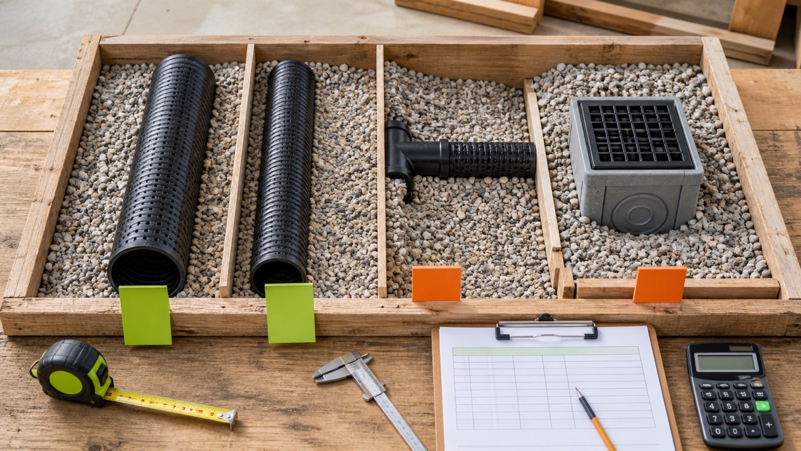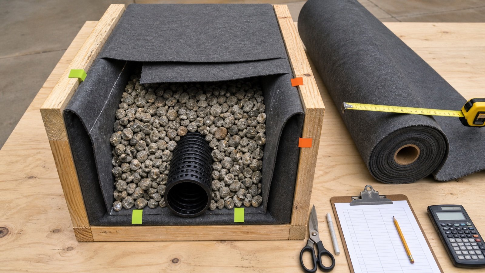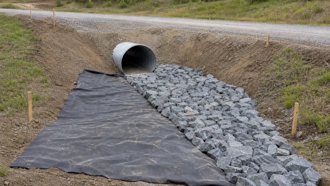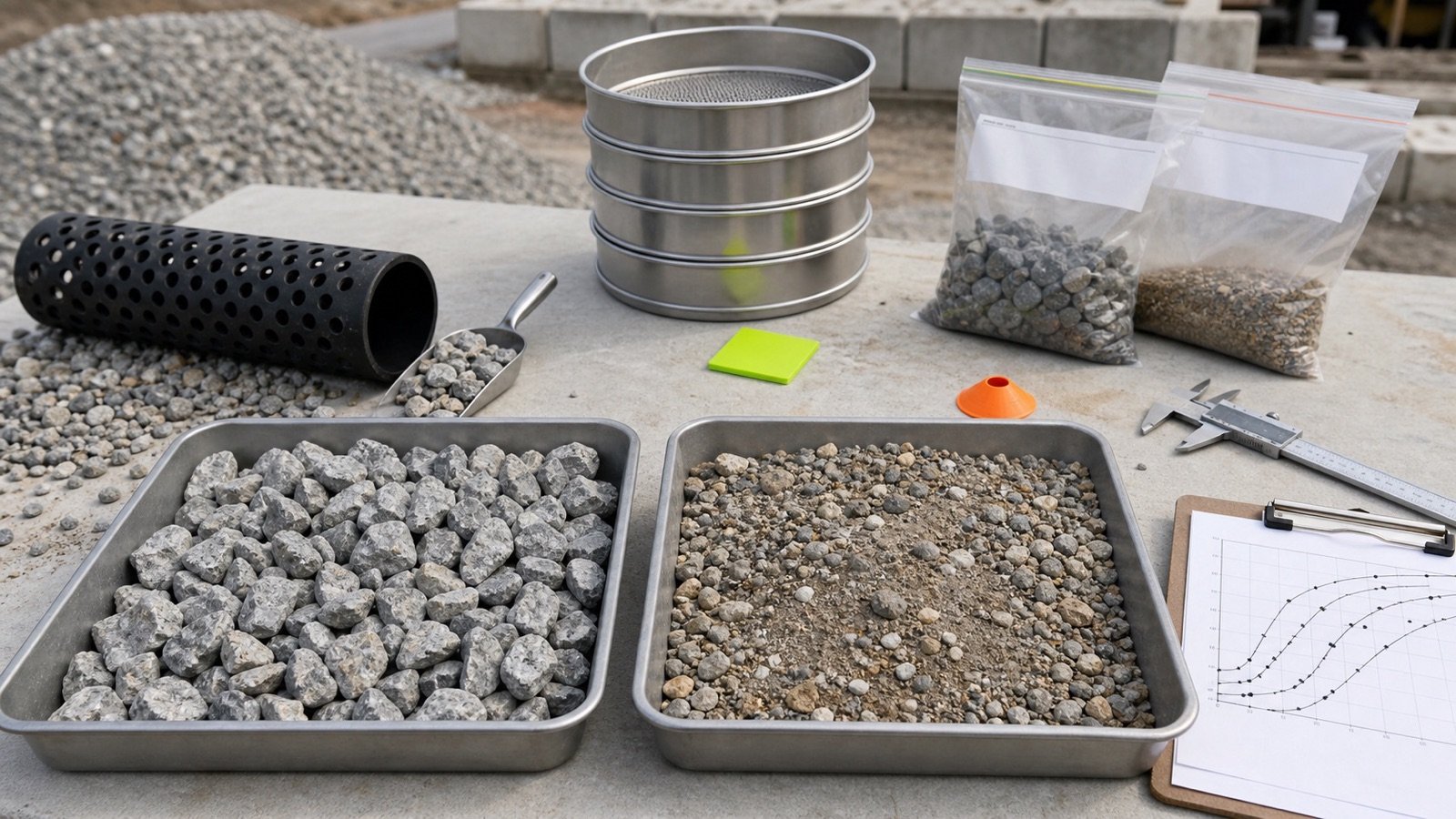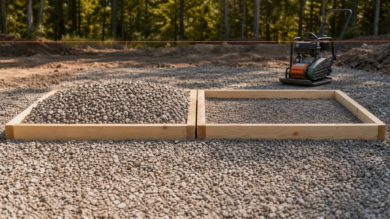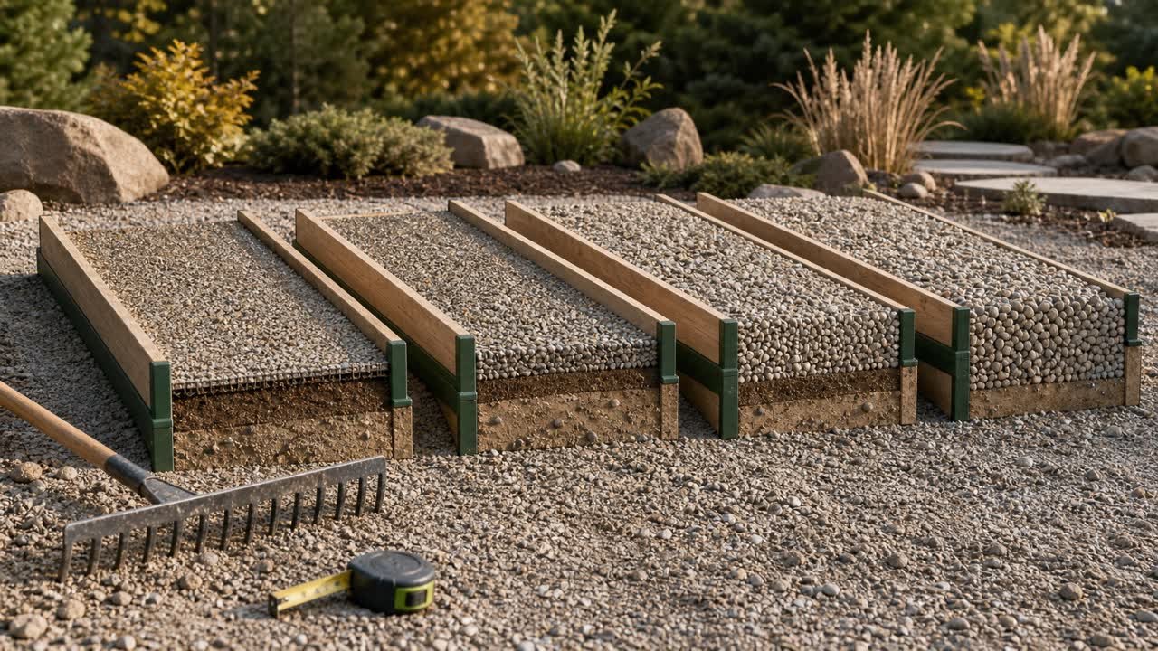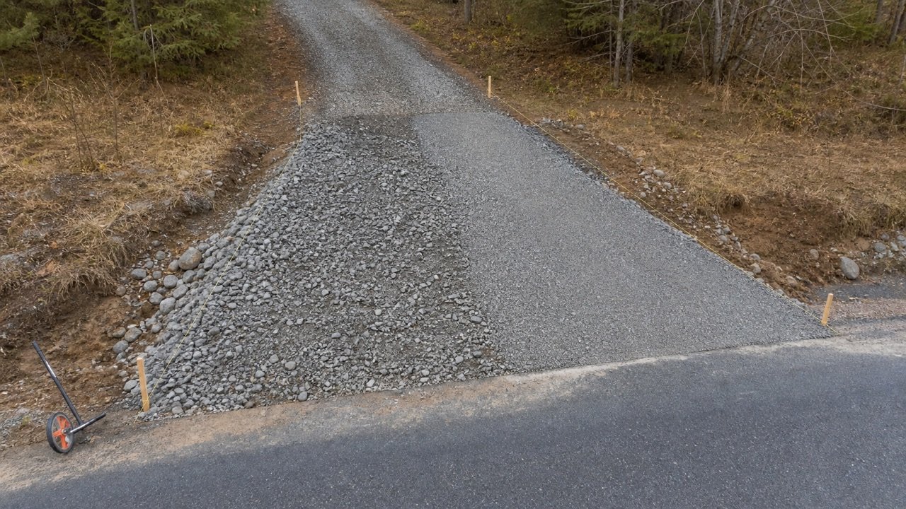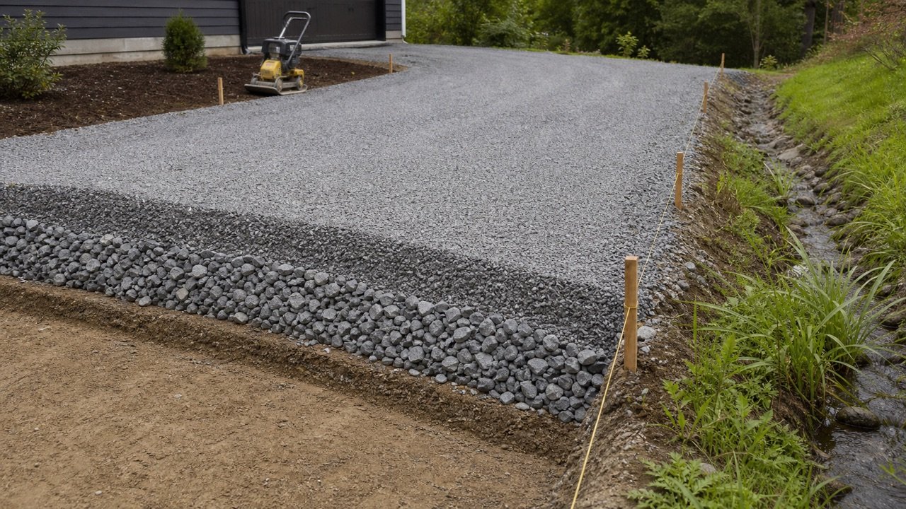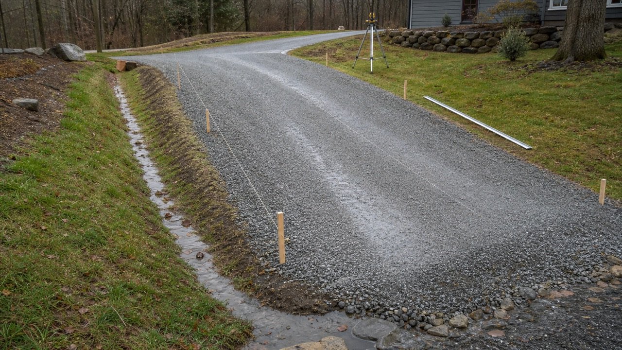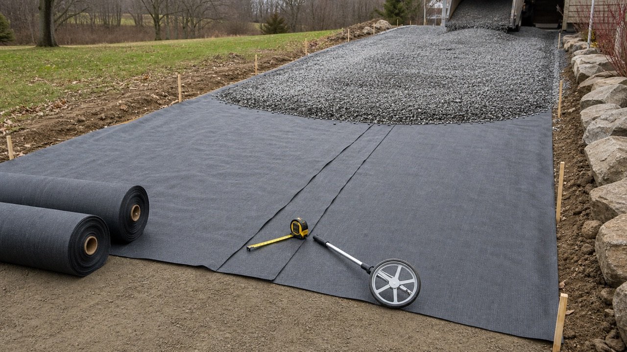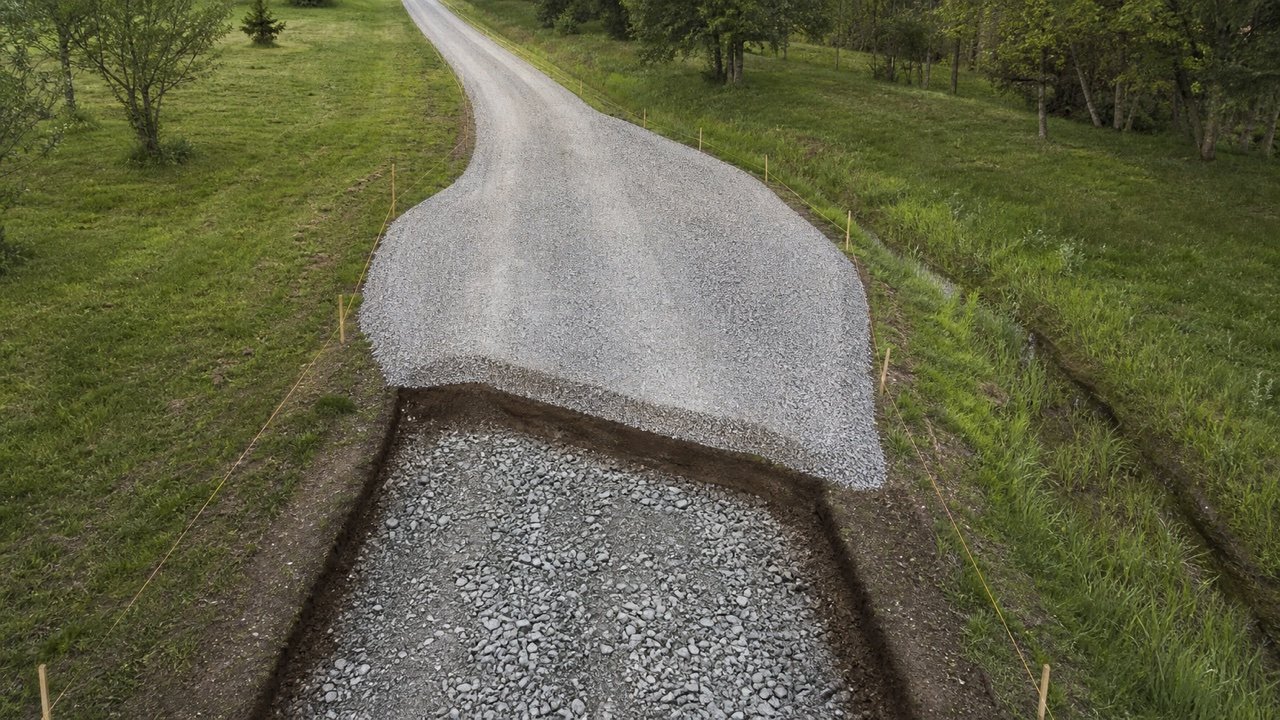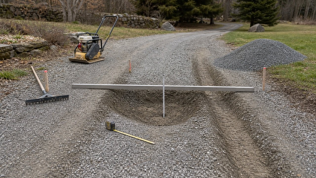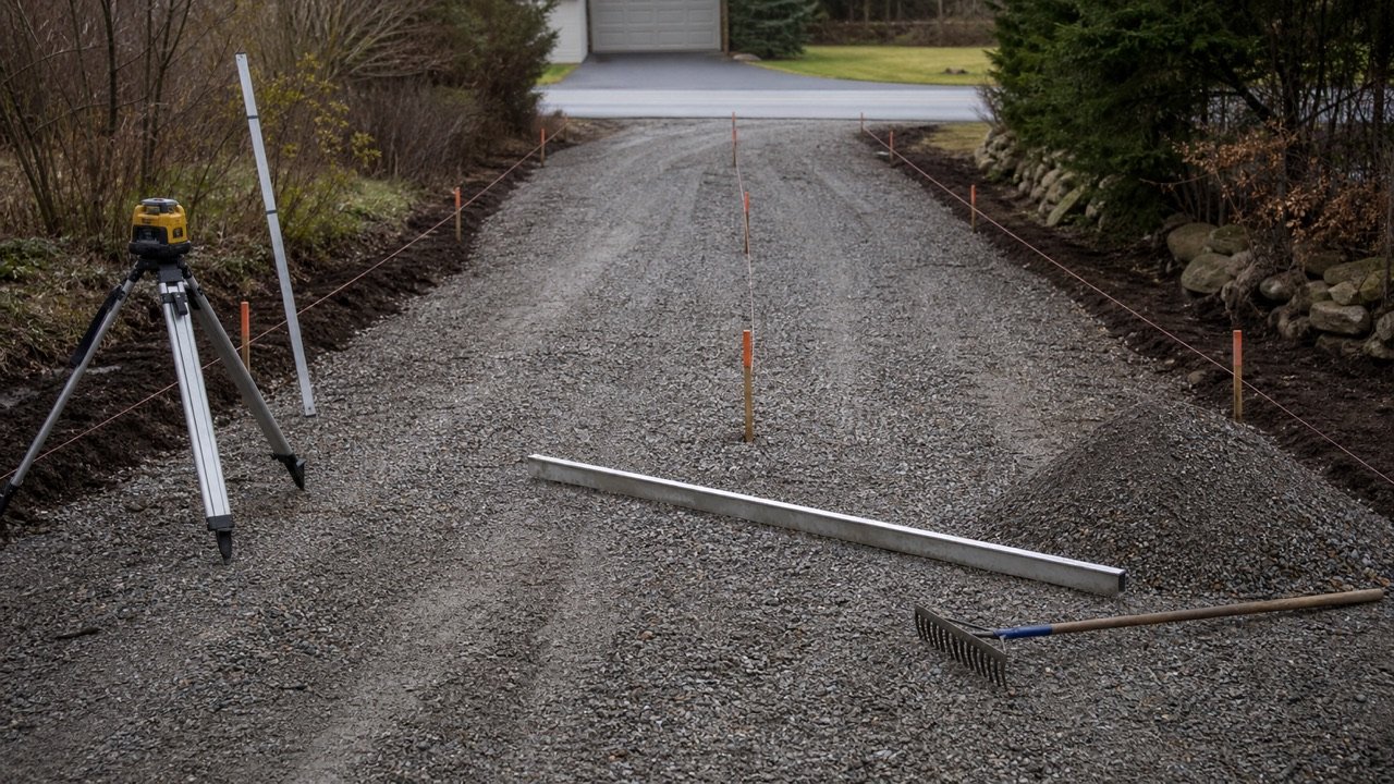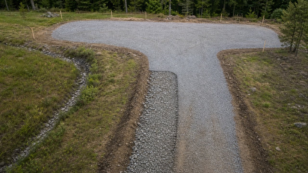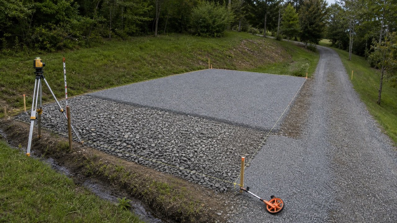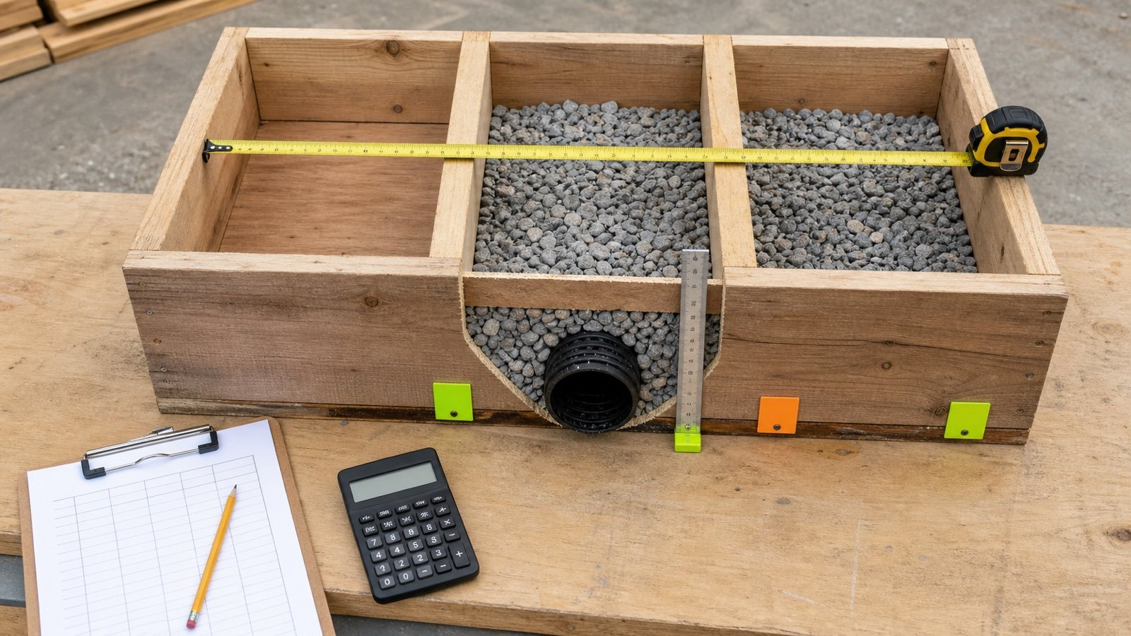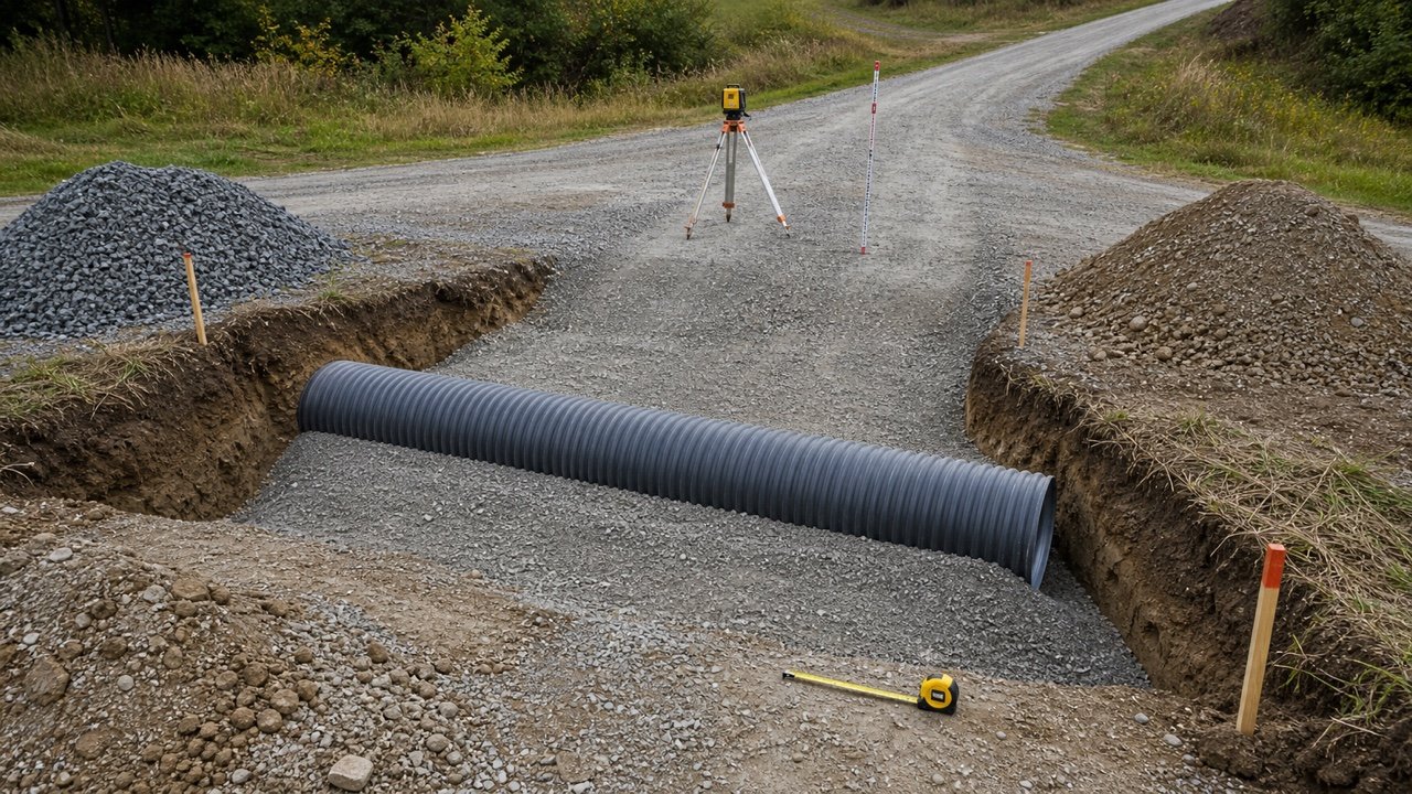
A gravel driveway culvert takeoff starts after the crossing detail is approved. You need the pipe type, actual outside diameter, installed length, invert levels, trench limits, bedding, backfill zones, cover, road layers, and end treatment before the quantity has a reliable basis.
Measure excavation, permanent pipe displacement, each fill material, reusable spoil, and the supplier order on separate lines. That separation makes the estimate checkable when the drawing, pipe system, ground condition, or selling unit changes.
How do you calculate bedding and backfill for a driveway culvert?
Calculate the gross excavation from the approved trench or embankment geometry. Divide the cross-section into bedding, pipe-zone material, final fill, road base, and surface aggregate, then subtract the pipe and any other permanent structure only from the zones they occupy.
Excavation volume = approved cross-sectional area × measured length
Net zone material = gross zone volume - pipe volume inside the zone - other permanent displacement
Total fill space = excavation volume - total permanent displacement
The pipe does not reduce excavation because the trench is empty when excavation occurs. It reduces the space available for material after installation. Keep bedding in the fill total because bedding remains in the completed crossing.
This method measures an approved crossing. Culvert capacity, diameter, material, class, gradient, cover, foundation, compaction, end protection, and permit conditions require project-specific design or authority approval.
Which documents and measurements are needed first?
Use the latest approved plan, cross-section, pipe schedule, permit, specification, and selected pipe manufacturer's installation instructions. Record the revision and resolve conflicts before measuring.
| Input | Record | Quantity effect |
|---|---|---|
| Crossing limits | Stations, offsets, ditch line, roadway limits, and skew | Defines the measured excavation and installed pipe length |
| Levels | Existing ground, formation, inlet invert, outlet invert, and finished road | Defines excavation depth, pipe grade, cover, and fill zones |
| Pipe | Material, shape, actual OD, barrel lengths, bells, couplers, and end sections | Defines permanent displacement and order length |
| Trench or fill section | Base width, side slopes, benches, undercut, and overbreak rules | Defines gross excavation and restoration space |
| Embedment | Foundation treatment, bedding depth, haunch, springline, crown surround, and material | Splits the lower fill into specified materials |
| Road build-up | Selected fill, subbase, base, surface gravel, crown, and tie-ins | Splits upper fill and driveway surface quantities |
| Ends | Headwalls, aprons, flared ends, riprap, geotextile, cutoff details, and slopes | Adds separate non-prismatic quantities |
| Material plan | Reuse acceptance, density, loose conversion, selling unit, and delivery increment | Converts geometric volume into import, export, and purchase quantities |
Use actual survey distances and levels. A product catalogue value or nominal pipe size cannot replace the selected pipe's outside dimensions.
How should the culvert cross-section be divided?
Follow the zone boundaries printed on the approved detail. Names differ across agencies and pipe systems, so each line in the takeoff should include its top and bottom elevation.
| Zone | Measure | Keep separate because |
|---|---|---|
| Undercut or foundation treatment | Accepted area below normal formation × length | Weak ground treatment may use a different material and limit |
| Bedding below invert | Approved bedding cross-section × length | It supports line and grade and remains beneath the pipe |
| Haunch and initial backfill | Gross specified envelope minus the pipe within it | Placement and material often differ from upper fill |
| Final backfill or embankment fill | Area above the pipe zone to the next road-layer limit | Reuse and compaction acceptance may change here |
| Subbase and base | Layer area or cross-section × length | Specified aggregate and finished thickness control ordering |
| Surface gravel | Finished plan area or section difference | The driveway crown, shoulders, and approaches can extend beyond the trench |
| End protection | Measured plan, section, count, or mass | Riprap, geotextile, aprons, and headwalls are irregular items |
Draw the zone lines on one cross-section and use the same labels in the worksheet, supplier request, and field records. A single line called "gravel" hides material changes and creates double counting.
What formulas apply to a constant rectangular trench?
Use rectangular geometry only where the width and depth remain constant over the measured length. Convert every dimension into one unit system before multiplying.
Vexc = L × W × D
Vbed = L × W × b
Apipe = π × OD² ÷ 4
Vpipe = Apipe × installed barrel length
Here, L is measured trench length, W is approved width, D is depth to formation, b is bedding depth below invert, and OD is actual outside diameter. Divide cubic feet by 27 for cubic yards. Dimensions in metres return cubic metres.
Use the Trench Excavation Volume Calculator for approved constant sections, then check the pipe measurement with the pipe outside diameter guide.
Which culvert quantities can the Trench Excavation Calculator check?
The calculator can check gross rectangular excavation only. It uses one length, excavation width, and average depth for each run. Keep pipe displacement, bedding, backfill zones, road layers, end treatments, and imported-material orders in the separate culvert takeoff.
| Quantity or condition | Calculator use | Remaining record |
|---|---|---|
| Constant vertical-sided excavation | Enter the approved length, excavation width, and average depth | Keep the in-place result as gross excavation |
| Several identical crossings or sections | Use the identical-runs field only when all 3 dimensions match | Identify each crossing and preserve its measured limits |
| Width or depth changes | Run each uniform rectangular section separately | Use station end areas for sloped, benched, or changing cross-sections |
| Pipe, bedding, and backfill zones | Not calculated | Deduct actual pipe displacement from the correct fill envelope and retain bedding as its own material |
| Road base, surface gravel, and end protection | Not calculated | Measure the approved driveway and end-treatment limits separately |
| Loose spoil and volume-based truck trips | Use only documented swell and truck-volume inputs | Check material classification, mass, payload, route, reuse, and disposal outside the tool |
Run the Trench Excavation Calculator once for each accepted rectangular excavation section. Bring the unrounded in-place results back to this worksheet before allocating pipe and material zones.
Worked imperial example for one culvert crossing
An approved constant section is 40 ft long, 4 ft wide, and 5 ft deep. The bedding is 0.5 ft below the pipe. The pipe OD is 30 in, or 2.5 ft. Initial backfill extends from pipe invert to 0.5 ft above the crown, giving a 3 ft-high envelope. Final fill occupies the remaining 1.5 ft.
| Quantity | Calculation | Result |
|---|---|---|
| Excavation | 40 × 4 × 5 | 800 ft³ = 29.629630 yd³ |
| Bedding | 40 × 4 × 0.5 | 80 ft³ = 2.962963 yd³ |
| Pipe displacement | π × 2.5² ÷ 4 × 40 | 196.349541 ft³ = 7.272205 yd³ |
| Gross initial-backfill envelope | 40 × 4 × 3 | 480 ft³ |
| Net initial backfill | 480 - 196.349541 | 283.650459 ft³ = 10.505573 yd³ |
| Final fill | 40 × 4 × 1.5 | 240 ft³ = 8.888889 yd³ |
| Total physical fill space | 80 + 283.650459 + 240 | 603.650459 ft³ = 22.357424 yd³ |
The independent balance is `800 - 196.349541 = 603.650459 ft³`. The fill zones and pipe occupy the full measured excavation. Surface gravel outside the 4 ft trench, end protection, overbreak, and supplier conversion remain separate.
How does the same check work in metric units?
A 12 m-long section is 1.2 m wide and 1.5 m deep. Bedding is 0.15 m. Pipe OD is 0.8 m. Initial backfill extends 0.2 m above the crown, so its envelope height is 1.0 m and the final zone height is 0.35 m.
| Quantity | Calculation | Result |
|---|---|---|
| Excavation | 12 × 1.2 × 1.5 | 21.600000 m³ |
| Bedding | 12 × 1.2 × 0.15 | 2.160000 m³ |
| Pipe displacement | π × 0.8² ÷ 4 × 12 | 6.031858 m³ |
| Net initial backfill | (12 × 1.2 × 1.0) - 6.031858 | 8.368142 m³ |
| Final fill | 12 × 1.2 × 0.35 | 5.040000 m³ |
| Total physical fill space | 2.16 + 8.368142 + 5.04 | 15.568142 m³ |
The second check is `21.6 - 6.031858 = 15.568142 m³`. Keep all values unrounded until the zone total is complete.
When can the full pipe circle be deducted from one zone?
Deduct the full circular barrel only from a zone that contains the complete pipe cross-section. Split the pipe area when a material boundary crosses the barrel.
- A bedding layer wholly below pipe invert contains no pipe area.
- An initial-backfill envelope from invert to above crown contains the full circle.
- A boundary at springline divides a circular pipe into 2 half-circle areas when the pipe is level.
- An arbitrary boundary through the pipe needs a circular-segment calculation, a checked CAD area, or another verified geometric method.
- Multiple pipes need each pipe area plus the approved spacing and trench geometry.
Subtracting the full pipe from bedding and again from backfill counts the same displacement twice. Deducting nominal inside diameter understates displacement when the outside diameter is larger.
How is the required culvert length measured?
Measure the installed pipe along its approved centerline between the defined inlet and outlet limits. Driveway tread width alone can miss shoulders, side slopes, skew, end sections, headwalls, or required projection.
- Mark the ditch or watercourse alignment and the crossing skew.
- Locate the approved inlet and outlet endpoints.
- Measure barrel, coupler, end-section, and structure limits using the project's measurement rules.
- Check stock lengths, joint insertion, field cuts, and required spare or handling policy.
- Keep ordered pipe length and excavation quantity length as separate worksheet fields.
Use slope length where the installed pipe follows a grade and the drawing measures along the barrel. Horizontal plan length and sloping centerline length differ on steeper crossings.
How are changing trench widths and depths calculated?
Measure a cross-sectional area at each station where formation, trench width, side slope, pipe position, or fill-zone limit changes. Multiply each segment by the average of its 2 end areas when the change between them is approximately linear.
Segment volume = segment length × (start area + end area) ÷ 2
For a trench with equal side slopes, the cross-sectional area is:
Area = base width × depth + side slope per side × depth²
Add stations at ditch bottoms, driveway edges, shoulders, crown changes, headwalls, undercut limits, rock transitions, and end slopes. A sudden step or a separate excavation needs its own shape rather than an averaged segment.
The changing trench sections guide explains station spacing and independent end-area checks.
How should bells, couplers and end structures be handled?
Use the installed outside envelope and measured length for every component that changes displacement or bedding. A constant barrel cylinder can miss local volume at couplers, bells, collars, end sections, headwalls, and aprons.
| Item | Method | Check |
|---|---|---|
| Bell or external coupler | Additional outside envelope over its installed length | Manufacturer dimension and joint count |
| Flared end section | Manufacturer geometry, count, or approved pay rule | Overlap with barrel and end fill |
| Headwall or cutoff wall | Net concrete or masonry shape | Openings, keys, footings, and reinforcement schedule |
| Concrete cradle or encasement | Gross concrete envelope minus pipe displacement | Approved section and construction joints |
| Apron or riprap basin | Plan zones, average thickness, and specified rock class | Filter or geotextile beneath it |
| Geotextile | Surface area plus approved overlaps, returns, and anchorage | Roll width, cut plan, and excluded faces |
Keep these items outside the constant trench formula until their limits are defined. Their irregular geometry can dominate a short residential crossing.
How do excavation, reusable spoil and imported fill reconcile?
Record the excavation in its in-place state, then classify excavated material by acceptance and destination. Reusable volume reduces imports only when the material meets the required use and its volume state matches the fill calculation.
Potential reusable in-place volume = excavation - permanent displacement - rejected or separately used zones
Undercut soil, wet or contaminated material, organic topsoil, oversize rock, mixed surface gravel, and excavated material outside the specification may need separate stockpiles or disposal. Accepted material can still require processing, moisture control, testing, haul, and placement.
Use the trench spoil balance guide to keep bank, loose, placed, and compacted states separate.
How is the geometric takeoff converted into an order?
Send each specified material to the supplier as its own line. State whether the quantity is compacted geometry, loose order volume, or mass.
- Sum each zone with unrounded geometry.
- Subtract accepted reuse in a compatible material state.
- Apply a documented product-specific loose-to-compacted relationship when the quote uses loose volume.
- Use a current supplier or test density when the quote uses mass.
- Add a justified handling allowance as a visible line.
- Round once to the supplier's selling increment.
- Confirm legal payload, partial-load policy, delivery access, dump location, fees, and quote date.
| Material | Geometric state | Supplier basis to confirm |
|---|---|---|
| Foundation or undercut replacement | Placed or compacted volume | Product, density or loose factor, and selling unit |
| Bedding | Specified net bedding volume | Gradation, moisture condition, mass or loose volume |
| Initial backfill | Gross envelope minus pipe and structures | Specified material, placement state, and increment |
| Final fill | Net accepted fill space | Imported or reused split and compaction basis |
| Road base and surface gravel | Finished layer quantity | Separate products, density, and delivery sequence |
| Riprap and filter | Approved end-treatment geometry | Rock class, filter product, mass, and placement basis |
The trench order quantity guide covers density, selling increments, loads, and quote records. Use the Gravel Calculator for approved uniform aggregate zones.
Common driveway culvert quantity mistakes
- Sizing the culvert from a blog or driveway width without authority or drainage review.
- Using nominal diameter as the displacement diameter.
- Measuring pipe length as tread width and omitting shoulders, skew, slopes, and ends.
- Reducing excavation by pipe volume.
- Removing bedding from total fill space even though it remains in the crossing.
- Deducting the full pipe circle from more than 1 material zone.
- Using 1 constant trench section through ditch and road-profile changes.
- Omitting bells, couplers, flared ends, headwalls, aprons, and erosion protection.
- Combining foundation, bedding, initial backfill, final fill, base, and surface gravel.
- Calling all excavated material reusable before testing or acceptance.
- Applying one hidden percentage for compaction, shrinkage, handling loss, and contingency.
- Converting cubic yards to tons with a generic density.
- Rounding every short segment before adding the crossing.
- Ordering before final invert, cover, and tie-in elevations are checked.
What should the field quantity record contain?
- Project, location, crossing ID, date, weather, and ground condition.
- Plan, permit, specification, pipe schedule, manufacturer guide, and revision.
- Benchmark, instrument, survey checks, stations, offsets, and skew.
- Inlet and outlet invert, formation, existing ground, and finished-road levels.
- Pipe material, shape, OD, barrel length, joints, couplers, and ends.
- Trench sections, undercut, overbreak, groundwater, and temporary-works limits.
- Zone names, materials, top and bottom levels, areas, lengths, and unrounded volumes.
- Pipe, structure, and encasement displacement by zone.
- Reusable, rejected, imported, exported, and stockpiled material by volume state.
- Supplier product, density or conversion evidence, selling unit, increment, payload, and quote date.
- Riprap, geotextile, headwall, apron, road base, surface gravel, and tie-in quantities.
- Prepared by, calculation check, revision, unresolved items, and approval status.
Safety and scope
Locate utilities before excavation. Control road traffic, ditch flow, groundwater, equipment movement, stockpiles, and public access. OSHA states that cave-ins pose the greatest trench risk and calls for appropriate sloping, shoring, or shielding, safe access, spoil separation, water checks, and inspection.
Use a competent person and the governing safety rules for the actual excavation. Keep workers out of an unsupported trench and outside suspended loads. Protect the inlet, outlet, and open crossing from storm flow during the work.
NRCS guidance ties culvert design to runoff, road use, vehicle class, watershed conditions, erosion, and local standards. This quantity guide does not calculate hydraulic capacity, structural pipe class, minimum cover, foundation stability, scour, fish passage, flood risk, or permit compliance.
Sources and source scope
- USDA NRCS, Conservation Practice Standard: Access Road (Code 560): drainage-design boundary, road-use context, runoff capacity, erosion, and local-standard checks.
- FHWA, Standard Specifications for Construction of Roads and Bridges on Federal Highway Projects, FP-24, and the current FP-24 standard-drawing directory: federal culvert excavation, bedding, balanced backfill, lift, material, and construction context.
- Prinsco Installation Guide: manufacturer-specific foundation, bedding, pipe handling, embedment, placement, and material guidance.
- Indiana DOT, Sample Calculations for Circular Pipe: checked circular-pipe displacement and separate backfill-zone geometry in an agency pay-quantity context.
- OSHA, Trenching and Excavation: U.S. workplace cave-in, protective-system, access, spoil, water, and inspection safety context.
- NIST Guide to the SI, Appendix B.8: cubic-foot and cubic-yard conversion factors.
Scope: agency and manufacturer documents apply within their stated systems and jurisdictions. They support the design boundary, placement sequence, and geometry checks. The approved project documents control the driveway crossing.
Review the bedding and backfill zone guide, check trench backfill deductions, set the finished approach with the gravel driveway drainage guide, or return to the Gravel planning hub.