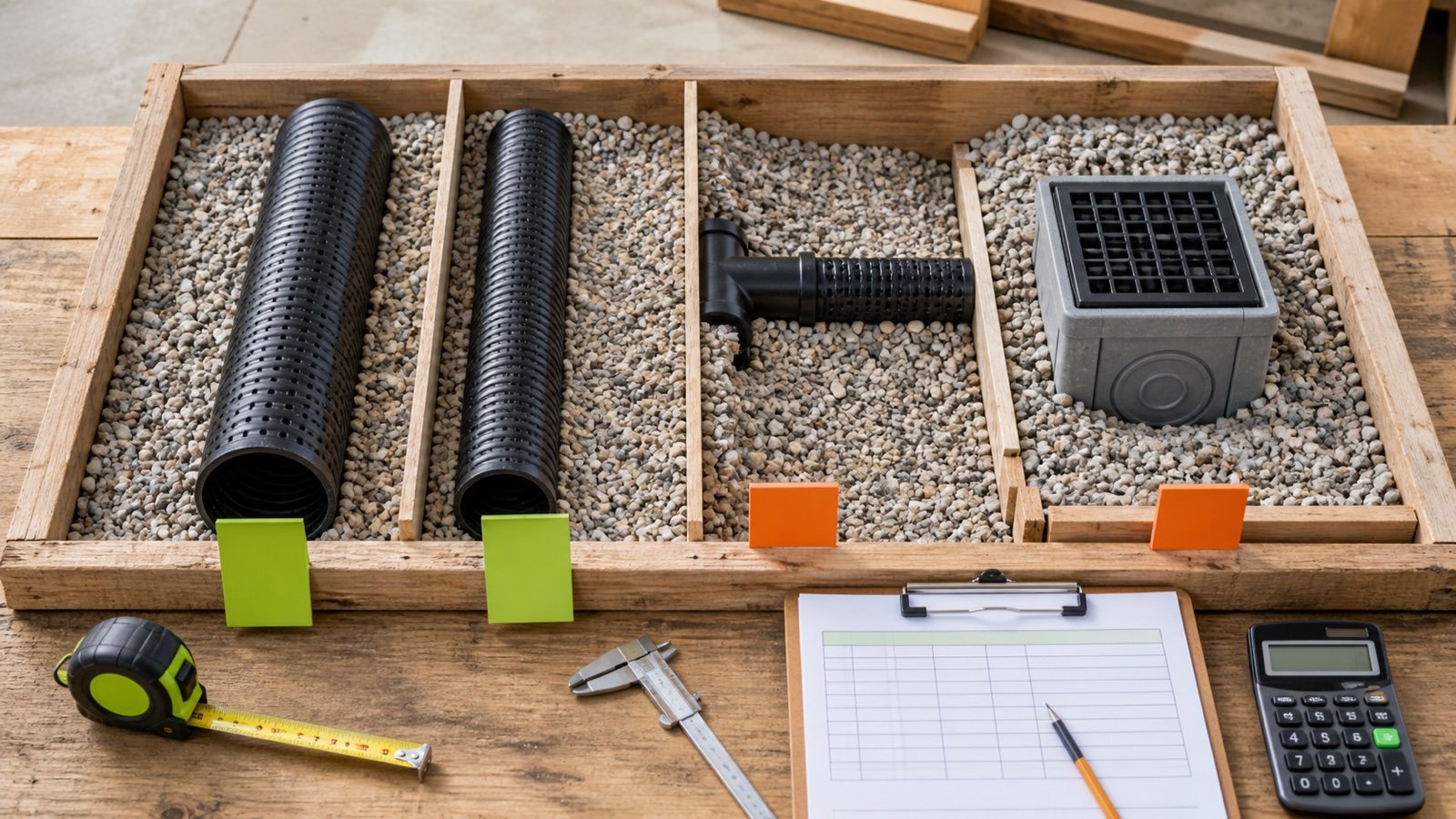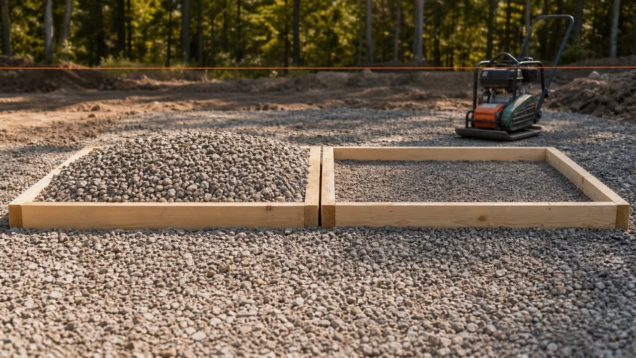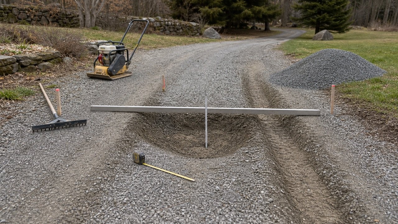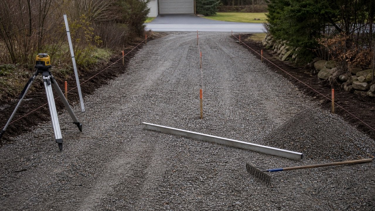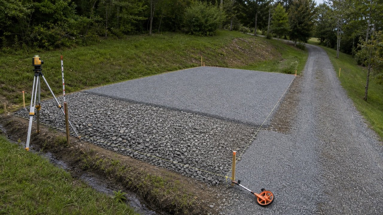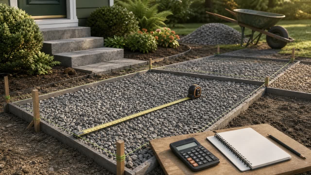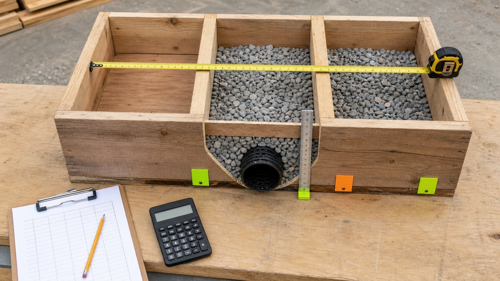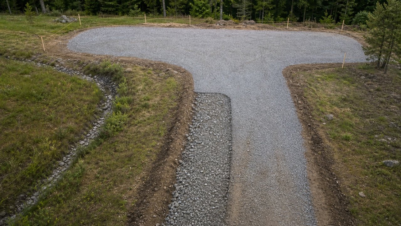
A gravel driveway turnaround takeoff starts with the approved movement area, not a convenient rectangle drawn around it. Circular loops, landscaped islands, hammerhead branches, curved tie-ins, and a retained driveway can all change the net construction footprint.
Measure the approved geometry first. Then calculate excavation, grading, geotextile, base, surface gravel, edging, drainage, and restoration as separate items because their limits may not match.
How do you calculate gravel for a driveway turnaround?
Divide the approved turnaround into non-overlapping shapes, add the included areas, and deduct retained surfaces and islands from the layers they displace. Multiply each net layer area by its accepted compacted thickness.
Net turnaround area = included shapes - overlaps - approved exclusions
Cubic yards = area in square feet × compacted depth in inches ÷ 324
Cubic metres = area in square metres × compacted depth in millimetres ÷ 1,000
Keep the unrounded result for each material. Convert compacted geometry to loose delivery volume or mass only after selecting evidence for the specific product and supplier selling state.
This method measures a turnaround that has already been approved for its intended vehicles and site. It does not choose the layout, turning path, emergency-access dimensions, pavement section, drainage, grade, gate position, or permit requirements.
Use the Driveway Gravel Calculator after the approved turnaround has been reduced to one checked rectangle, uniform taper, or net known area. Keep overlapping shapes, islands, retained driveway, and differing layer limits in the takeoff before entering a depth.
Is a turnaround the same as a driveway turnout?
No. A turnaround lets a vehicle reverse direction at or near the end of an access route. A turnout or passing place lets vehicles pass along a narrow route and normally has different geometry, spacing, and operating needs.
Label the measured feature from the approved plan before using a formula. Combining passing bays, parking pads, aprons, and terminal turnarounds under one extra-area line makes quantities hard to verify and can conceal a design conflict.
| Feature | Primary function | Quantity boundary |
|---|---|---|
| Terminal turnaround | Change travel direction near the route end | Approved turning and clear-operating footprint |
| Turnout or passing place | Allow vehicles to pass on a narrow route | Widening, tapers, and retained route overlap |
| Parking pad | Store vehicles and provide approved maneuvering space | Parking, access, aisle, and connection limits |
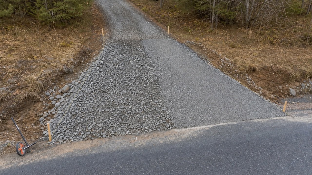
| Road apron | Join the private driveway to the road edge | Road tie-in, flare, culvert, and restoration limits |
| Pull-off or loading area | Provide a defined stopping or service zone | Approved use area and its pavement section |
Which layout should be measured?
Use the latest approved site, fire-access, grading, drainage, and pavement documents. Current authority examples show circles, T shapes, Y shapes, and hammerheads, but their triggers, dimensions, placement rules, and approval paths differ.
Ontario Fire Department Standard B-002, King County's 2026 fire-access checklist, Clackamas County roadway standards, and Country Fire Authority Victoria guidance do not create one worldwide turnaround template. They demonstrate why a generic online dimension must not replace the governing authority and approved plan.
- Record the plan title, revision, issue date, authority, and approval status.
- Identify the design vehicle and required clear-operating area.
- Mark the construction joint between retained and new work.
- Locate gates, buildings, walls, utilities, covers, trees, slopes, drainage assets, and property limits.
- Confirm whether parking, storage, landscaping, or snow placement is allowed within the operating area.
- Record the formation levels and pavement section for every branch or ring.
A measured gravel quantity cannot confirm that a vehicle can complete the movement. Turning-path analysis, emergency access, load capacity, overhead clearance, and operational clearance remain design checks.
How is a circular turnaround measured?
Use the approved outer radius when the construction boundary is a full circle. Measure the radius from the stated center to the specified construction edge, not to a wheel path, curb face, survey stake, or visible gravel edge unless the plan defines that line.
Circle area = π × radius²
A circular boundary often meets a straight driveway through a neck or flared connection. Add that connection as its own rectangle, trapezoid, triangle, curve, or surveyed polygon, then deduct any area already inside the circle.
Do not multiply the circle's diameter by its diameter. That returns the area of a surrounding square, which is about 27% larger than the circle before any connection adjustment.
How is a circular turnaround with an island measured?
Subtract the approved inner island from the outer circle when both share one center. This produces an annulus, commonly called a ring.
Ring area = π × (outer radius² - inner radius²)
Use separate measured shapes when the island is off-center, oval, irregular, or interrupted by a mountable apron. Deduct the island only from the layers it displaces. A geotextile, drainage layer, root barrier, or structural system may continue below an open-looking island if the approved detail says so.
| Measurement | Check before calculation |
|---|---|
| Outer radius | Specified center and construction boundary |
| Inner radius or island polygon | Actual displaced layer and any mountable zone |
| Driveway connection | Overlap with the circle counted once |
| Flared or curved tie-in | Surveyed curve, offsets, or checked drawing area |
| Outer and inner edge | Which line controls edging, shoulder, or restoration |
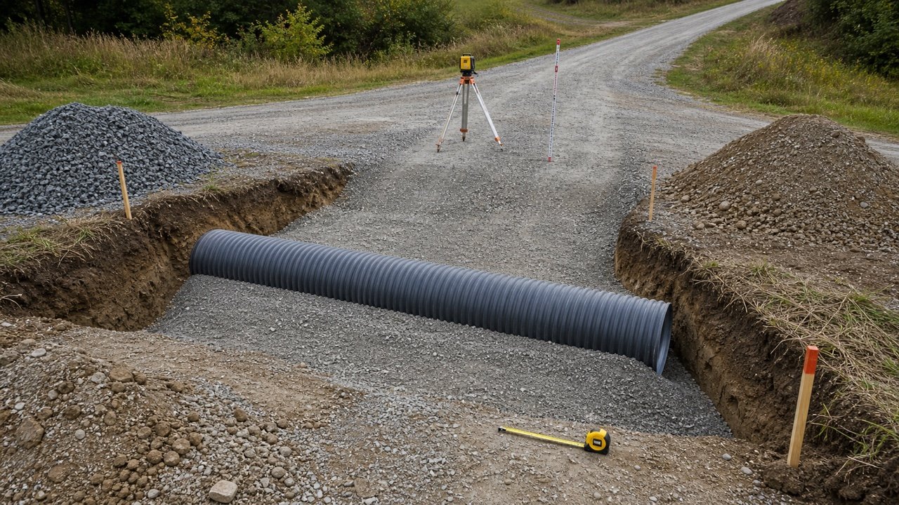
| Drainage opening or crossing | Whether it removes, replaces, or continues a layer |
How is a hammerhead, T, or Y turnaround measured?
Split the approved outline into rectangles, triangles, trapezoids, sectors, or surveyed polygons. Add each non-overlapping piece and subtract the retained driveway, islands, drainage features, and other approved exclusions.
A hammerhead often has a straight crossbar meeting the driveway stem. A T can use the same basic composite method. A Y usually adds angled branches that are better measured as rectangles plus triangles or as a checked polygon.
- Trace the outer construction boundary.
- Mark the existing driveway area that will remain.
- Draw non-overlapping shapes for the new work.
- Calculate each shape using perpendicular dimensions.
- Deduct exclusions from the affected layers only.
- Check the total against a scaled drawing, coordinates, or an independent method.
Use a triangle's perpendicular height, not its sloping side. For a tapered branch with straight sides, multiply its perpendicular length by the average of the 2 end widths.
How should the existing driveway overlap be deducted?
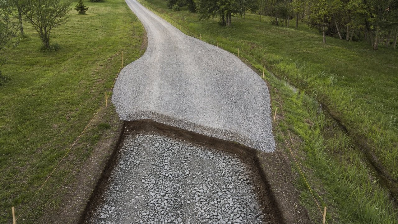
Deduct only the retained construction that lies inside the gross turnaround shape. If the existing driveway is excavated and rebuilt through the turnaround, it remains part of the new layer footprint.
| Existing condition | Area treatment | Record needed |
|---|---|---|
| Existing section retained | Deduct its measured overlap from new work | Joint line, condition, levels, and acceptance |
| Existing surface removed, base retained | Deduct overlap from base but include it in new surface | Removal depth and retained-base limits |
| Full-depth reconstruction | Include overlap in excavation and all replacement layers | Demolition and reconstruction limits |
| Local transition or feathering | Measure the variable-depth zone separately | Length, widths, end depths, and product |
| Unverified existing section | Keep the decision open | Test pits, records, inspection, or responsible approval |
A faded gravel edge does not prove the structural boundary. Locate the accepted joint and any weak or contaminated material before finalizing a retained-area deduction.
Why does every layer need its own footprint?
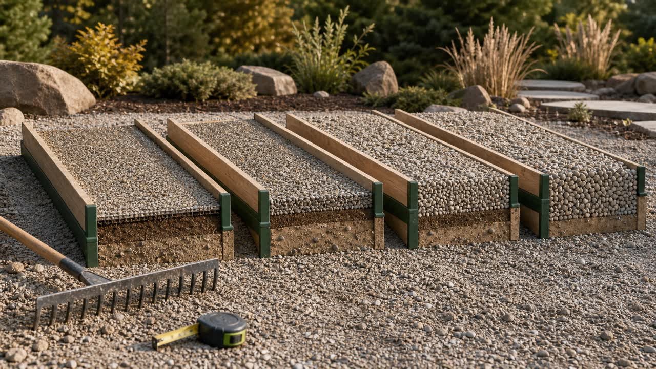
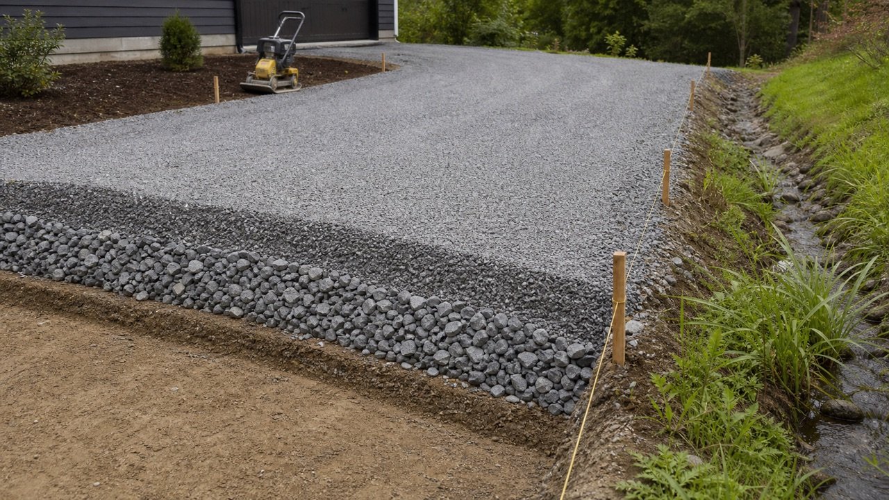
The finished gravel outline may be smaller than excavation, stabilization, geotextile, or shoulder work. A drain, paved strip, island, or retained driveway can also interrupt one layer while another continues beneath it.
| Item | Measurement basis | Reason to keep it separate |
|---|---|---|
| Clearing and topsoil | Approved disturbance area and removal depth | Organic material has a different handling route |
| Excavation and undercut | Existing ground to accepted formation | Depth and limits respond to ground conditions |
| Structural or grading fill | Accepted surface to target formation | Fill can form wedges and side slopes beyond the surface |
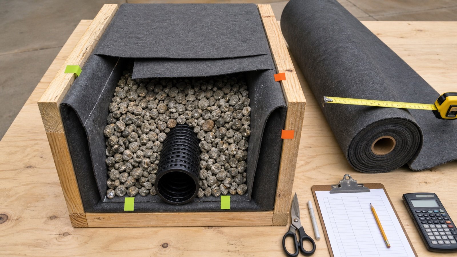
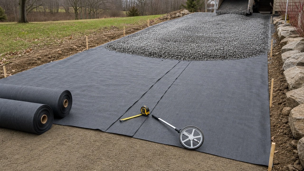
| Geotextile or geogrid | Support surface plus specified overlaps and returns | Roll layout differs from gravel volume |
| Subbase and base | Each net footprint × compacted thickness | Products, depth, and lateral extent can differ |
| Surface gravel | Finished gravel footprint × compacted thickness | It can stop at a joint, island, drain, or mountable zone |
| Edging and shoulder | Specified line, width, cross-section, and gaps | Length and area are different order units |
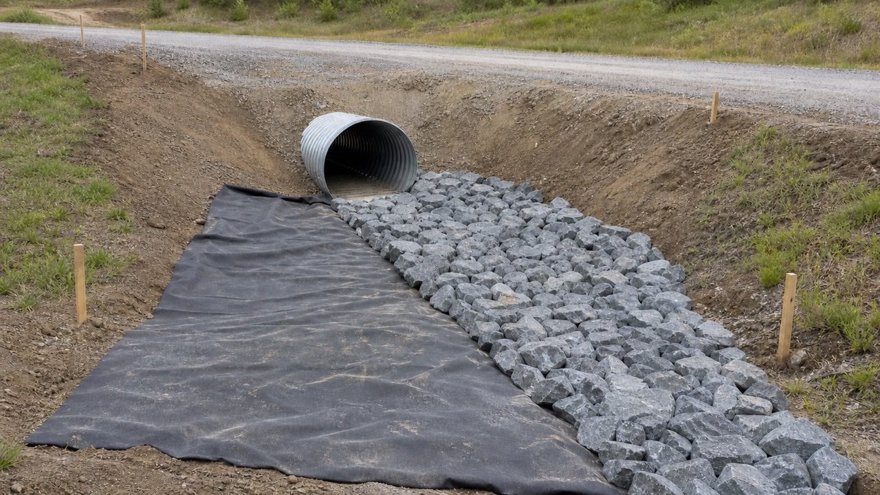
| Drainage and restoration | Approved swales, drains, outlets, slopes, and disturbed land | These use separate materials and geometry |
Use the driveway layer and depth guide to keep each selected compacted depth tied to the project source. The geotextile roll guide covers panels, overlaps, returns, and roll rounding.
How should a turnaround be entered in the Driveway Gravel Calculator?
The Driveway Gravel Calculator accepts one rectangle, one uniform taper, or one checked plan area. Complete the overlap and exclusion ledger first, then enter only the compacted depth and supplier inputs approved for that footprint.
| Checked quantity | Calculator mode | Required boundary |
|---|---|---|
| Rectangular hammerhead branch or crossbar | Rectangle | Remove any retained-driveway overlap before entry, or calculate the non-overlapping pieces separately |
| Straight branch with uniformly changing width | Uniform taper | Verify perpendicular length, both end widths, and an intermediate width |
| Circle, ring, Y, T, or composite outline | Known area | Enter the checked net area produced by this article or an approved drawing |
| Base and surface share the same net footprint | Both layer inputs | Record separate compacted depths and supplier data |
| Base and surface footprints differ | Separate calculations | Keep the inactive layer blank and use the correct net area for each run |
| Excavation, grading fill, side slopes, or drainage vary | Use the measured methods on this page | A uniform layer entry does not represent changing ground or formation |
Worked imperial hammerhead example
An approved hypothetical hammerhead crossbar is 60 ft long and 20 ft deep. A retained 12 ft-wide driveway crosses the full 20 ft depth. The net new area receives an 8 in compacted base and a 2 in compacted surface.
| Quantity | Calculation | Result |
|---|---|---|
| Gross crossbar | 60 × 20 | 1,200 ft² |
| Retained-driveway overlap | 12 × 20 | 240 ft² |
| Net new footprint | 1,200 - 240 | 960 ft² |
| Compacted base | 960 × 8 ÷ 324 | 23.703704 yd³ |
| Compacted surface | 960 × 2 ÷ 324 | 5.925926 yd³ |
| Total compacted geometry | 23.703704 + 5.925926 | 29.629630 yd³ |
The 60 ft and 20 ft dimensions are arithmetic inputs for this hypothetical approved layout. They are not a fire-access standard or recommendation. If the driveway overlap is rebuilt, the affected 240 ft² must return to the relevant layer totals.
Worked metric circular-ring example
An approved hypothetical ring has a 9 m outer radius and a 3 m retained inner island. The measured ring receives a 200 mm compacted base and a 50 mm compacted surface.
| Quantity | Calculation | Result |
|---|---|---|
| Net ring area | π × (9² - 3²) | 226.194671 m² |
| Compacted base | 226.194671 × 200 ÷ 1,000 | 45.238934 m³ |
| Compacted surface | 226.194671 × 50 ÷ 1,000 | 11.309734 m³ |
| Total compacted geometry | 45.238934 + 11.309734 | 56.548668 m³ |
This fixture measures the ring itself. Add or deduct the driveway connection and flare according to their actual boundary. Keep base and surface as separate products through supplier conversion.
How much edging does a circular turnaround need?
Use circumference when the measured edge is a full circle. Calculate outer and inner edges separately, then remove openings and add only the specified transitions, returns, joints, or laps.
Circumference = 2 × π × radius
For the metric ring example, the 9 m outer radius gives 56.548668 m of outer edge. The 3 m inner radius gives 18.849556 m. Both full edges total 75.398224 m before connection openings or product-specific adjustments.
The material order may follow a curb face, edging centerline, fabric return, shoulder boundary, or restoration limit. Use the line named in the detail rather than assuming every circular item follows the same radius.
How are curved tie-ins and irregular edges checked?
Use surveyed coordinates, a checked drawing area, or short measured offsets for a curve that is not a true circle. Split simple tapers into trapezoids or triangles and keep the pieces non-overlapping.
- Confirm the drawing scale and revision before measuring a digital area.
- Keep the curve's centerline, inner edge, and outer construction edge distinct.
- Add enough offsets to follow a compound curve or flare.
- Close the polygon and check for self-intersections or duplicate vertices.
- Compare the result with a bounding rectangle and a second method.
Rounding every short offset or small shape can compound the error. Retain practical precision through the complete footprint and round the final material quantity once.
How do slope and drainage change the quantity?
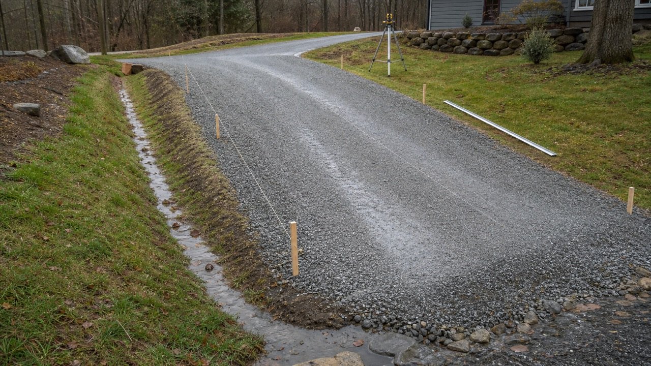
A plan area multiplied by one layer depth measures a uniform pavement layer. It does not measure variable excavation, grading fill, side slopes, ditches, swales, drains, or erosion protection.
Record existing ground and target formation elevations at branch ends, the driveway stem, circle quarters, grade breaks, low points, and fixed tie-ins. Use grids, triangles, cross-sections, or a checked surface model when cut or fill varies.
Triangular cell volume = triangle plan area × average depth at its 3 vertices
Keep positive fill and negative cut separate. Excavated material becomes usable fill only after its material type, condition, processing, specification, state, and responsible acceptance are confirmed.
The driveway drainage and grade guide explains crossfall and runoff records. For a detailed sloped-fill workflow, use the parking-pad quantity guide without transferring its dimensions or design assumptions.
Does a gravel turnaround count as permeable?
Loose gravel at the surface does not establish stormwater performance. Gradation, compaction, underlying layers, soil infiltration, groundwater, slope, clogging, storage, drains, and the approved outlet affect what happens to runoff.
U.S. EPA stormwater guidance treats permeable pavement and vegetated swales as designed practices. Measure open-graded storage stone, underdrains, filter layers, swales, channels, outlets, and erosion protection from the approved drainage detail.
A circular island does not automatically receive runoff safely. Check its inlet level, soil, overflow route, edge treatment, vegetation, maintenance, and relationship to the structural pavement.
Which conditions require a new design decision?
Pause the quantity when the site no longer matches the approved geometry, pavement, ground, or access assumptions. Adding gravel cannot resolve an undefined turning path, unstable edge, blocked clearance, or missing drainage route.
| Condition | Quantity effect | Decision needed |
|---|---|---|
| Emergency or fire access | Footprint, loading, grade, gate, clearance, and surfacing may change | Use the governing authority and approved access design |
| RV, trailer, truck, or service vehicle | Turning path, branch length, width, edge support, and section may change | Confirm the design vehicle and pavement loading |
| Soft, wet, organic, or pumping ground | Undercut, stabilization, drainage, and layer limits may increase | Obtain required subgrade or geotechnical direction |
| Steep or irregular terrain | Cut, fill, side slopes, retaining, drainage, and safety scope expand | Use surveyed grading and engineered support where required |
| Gate or security control | Setback, stacking, operating clearance, and foundations affect quantities | Confirm emergency operation and approved placement |
| Utilities, septic assets, wells, trees, or easements | Clearance, protection, excavation, and usable footprint change | Locate assets and obtain responsible approval |
| Parking or storage inside the turnaround | Clear operating area may be reduced even when gravel area is unchanged | Confirm permitted operations and markings |
| Snow storage or roadside drainage | Usable area, edge, outlet, and seasonal operation can change | Resolve the maintenance and drainage plan |
How is compacted geometry converted into an order?
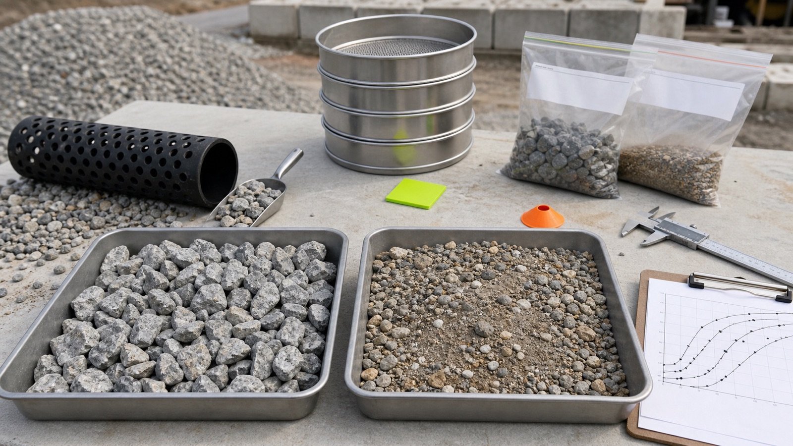
Convert each accepted layer using evidence for the selected product and the state in which it is sold. A geometric cubic yard of compacted base does not automatically equal a loose cubic yard delivered or a fixed mass.
- Sum the approved unrounded footprint and compacted volume for each product.
- Separate accepted reuse from imported material.
- Use a documented loose-to-compacted relationship when the supplier sells loose volume.
- Use product-specific bulk density in a matching moisture and placement state when the supplier sells mass.
- Show any handling allowance as a separate line supported by project conditions.
- Round once to the supplier's selling increment.
- Confirm minimum order, legal payload, delivery access, unloading position, fees, and quote expiry.
The EPA-hosted Gravel Roads quantity appendix labels its coverage depth as uncompacted and warns that compaction changes coverage. Use the loose versus compacted gravel guide before converting the measured section. Check current supplier inputs with the gravel cost guide.
Common turnaround quantity mistakes
- Selecting fire-access dimensions from an unrelated jurisdiction.
- Treating a turnout, parking pad, apron, or loading area as the terminal turnaround.
- Measuring the bounding square around a circle.
- Forgetting the inner island or deducting it from layers that continue below it.
- Counting the retained driveway inside both the driveway and turnaround totals.
- Deducting retained pavement even though full-depth reconstruction is planned.
- Using the same footprint for excavation, fill, fabric, base, surface, edging, and drainage.
- Measuring a radius to the wrong edge or from the wrong center.
- Using a sloping triangle side as its perpendicular height.
- Multiplying the entire site by the deepest cut or fill.
- Netting excavated material against fill before suitability and state are accepted.
- Calling loose gravel a complete permeable-pavement system.
- Applying one density, compaction factor, waste percentage, or truck capacity to every product.
- Rounding every branch, layer, and exclusion before the material total is complete.
- Ordering before the joint, formation, drainage, and operating clearances are accepted.
What should the turnaround quantity record contain?
- Project, location, use, intended vehicles, date, weather, and existing condition.
- Approved site, fire-access, grading, drainage, pavement, utility, and permit documents with revisions.
- Layout type, center points, radii, branches, corners, curves, driveway joint, and exclusions.
- Gross area, overlap ledger, net area, and an independent geometry check.
- Existing and target elevations, cut and fill method, survey datum, and grade breaks.
- Separate footprints and compacted depths for every layer and treatment.
- Edge lengths, connection openings, shoulders, drains, slopes, and restoration.
- Product specification, material state, unrounded volume, density or conversion evidence, and allowance.
- Supplier, selling unit, increment, minimum order, payload, delivery route, fees, and quote date.
- Open decisions, field changes, inspections, approvals, photographs, preparer, and checker.
Safety and scope
Locate overhead and buried utilities, control construction traffic, protect open excavations and unstable edges, and keep people clear of dumping, grading, and compaction. OSHA excavation guidance describes cave-in and related hazards for US workplaces; apply the rules and competent-person decisions required at the site.
This guide checks quantity geometry and supplier records. It does not approve emergency access, vehicle movement, pavement loading, subgrade, retaining work, drainage capacity, utilities, gates, land use, permits, or construction.
Sources and source scope
- Ontario Fire Department, On-Site Turnaround/Hammerhead Requirements, Standard B-002: one current local example of turnaround triggers, approval, and site-dependent controls.
- King County, Residential Fire Access & Water Supply Checklist, February 2026: one jurisdiction's fire-access approval, alternative-layout, and placement rules.
- Clackamas County Roadway Standards: local turnaround, turnout, access, grade, and gate context.
- Country Fire Authority Victoria, Property Access for Emergency Services: T, Y, and circular layout examples within its own jurisdiction.
- U.S. EPA, Stormwater Management Practices at EPA Facilities: designed permeable-pavement, swale, and runoff-management context.
- Gravel Roads Manual, Appendix C: Quantity Calculations: historic loose coverage and its stated compaction limitation.
- NIST Guide to the SI, Appendix B.8: unit relationships used in the examples.
- OSHA, Trenching and Excavation: US workplace excavation-hazard scope.
Source scope: the authority documents show that access rules vary and need local approval. They do not provide one universal turnaround size, gravel depth, product, density, waste factor, slope, or pavement section. The examples verify geometry for stated hypothetical approved layouts.
Process uniform shapes with the Gravel Calculator, measure the road connection with the driveway apron guide, or return to the Gravel planning hub.