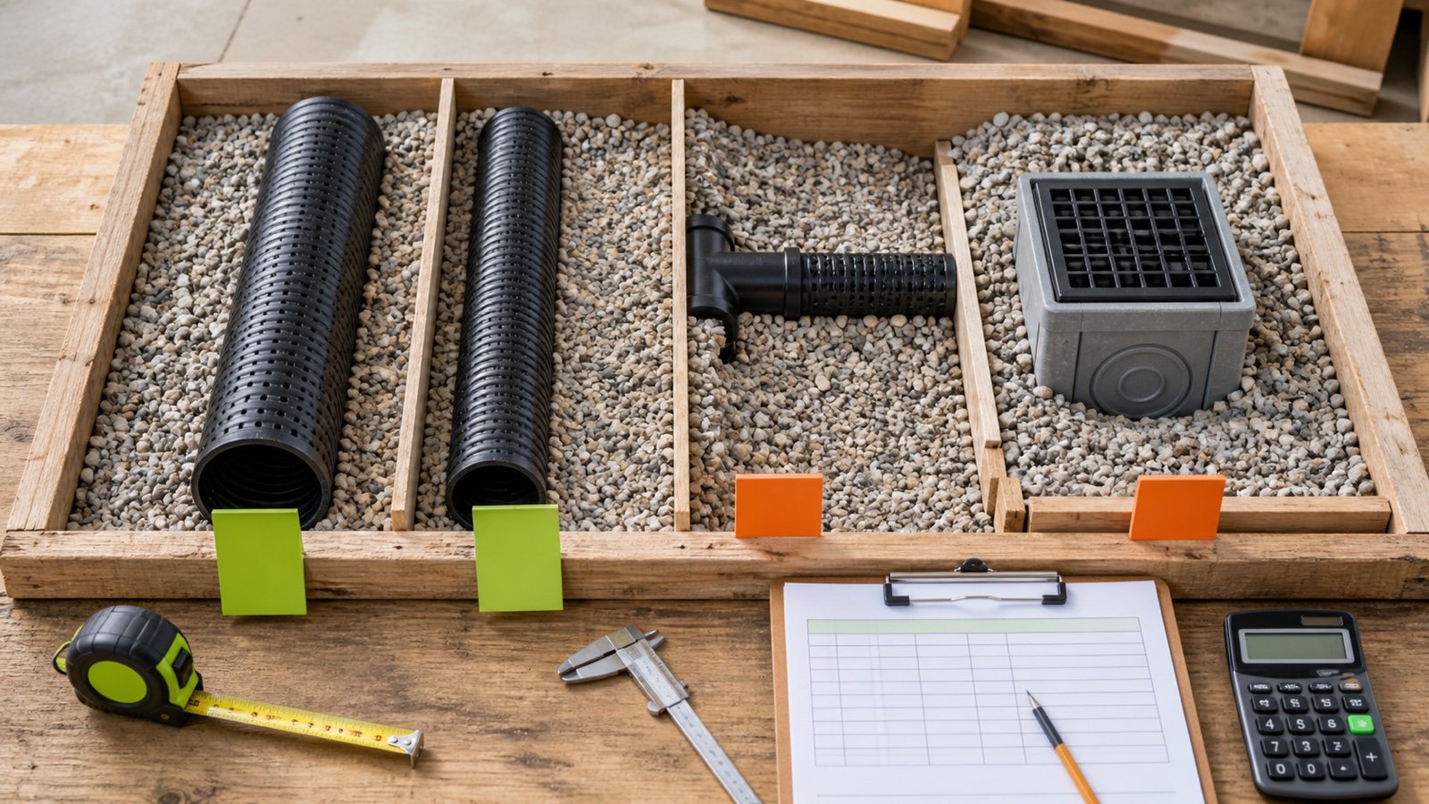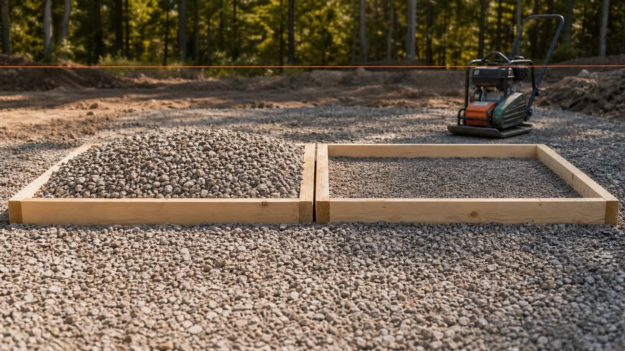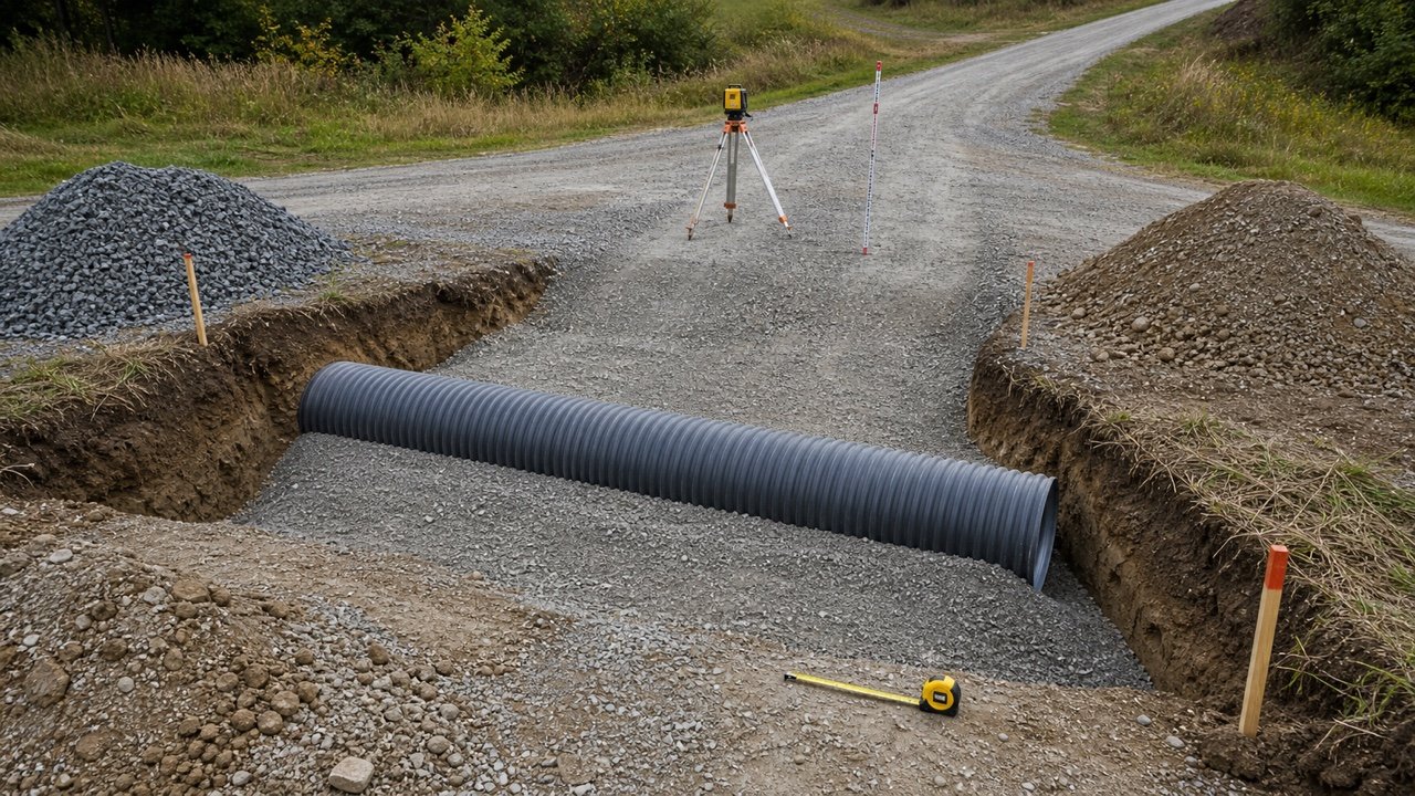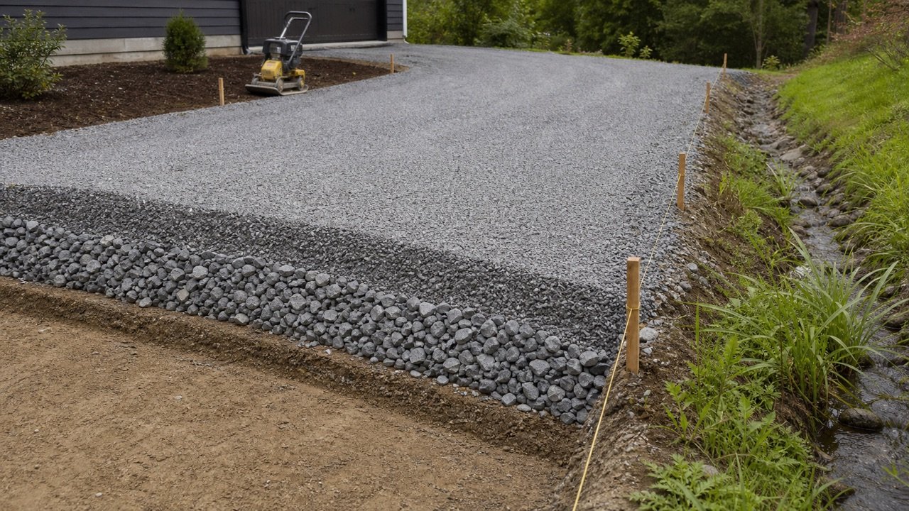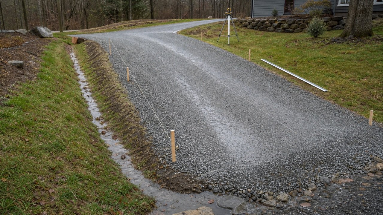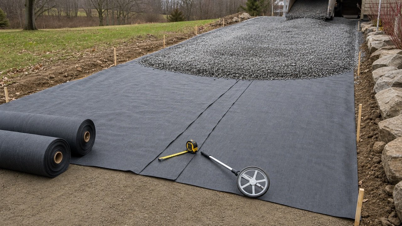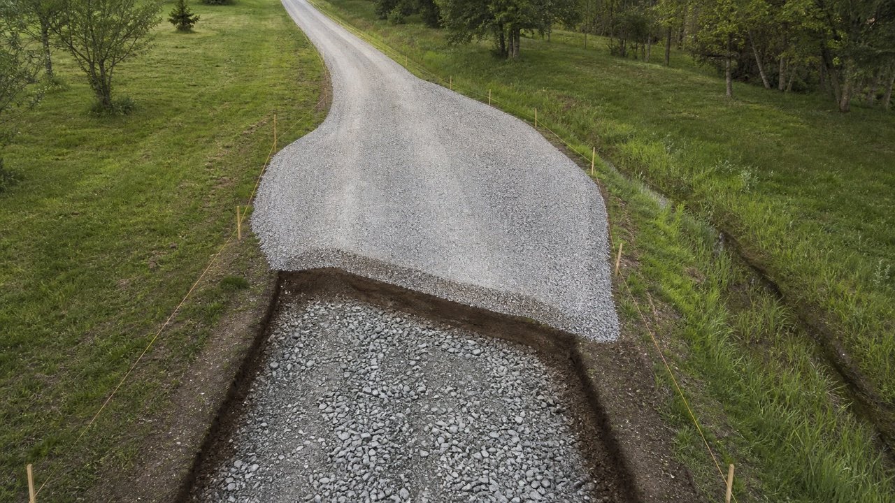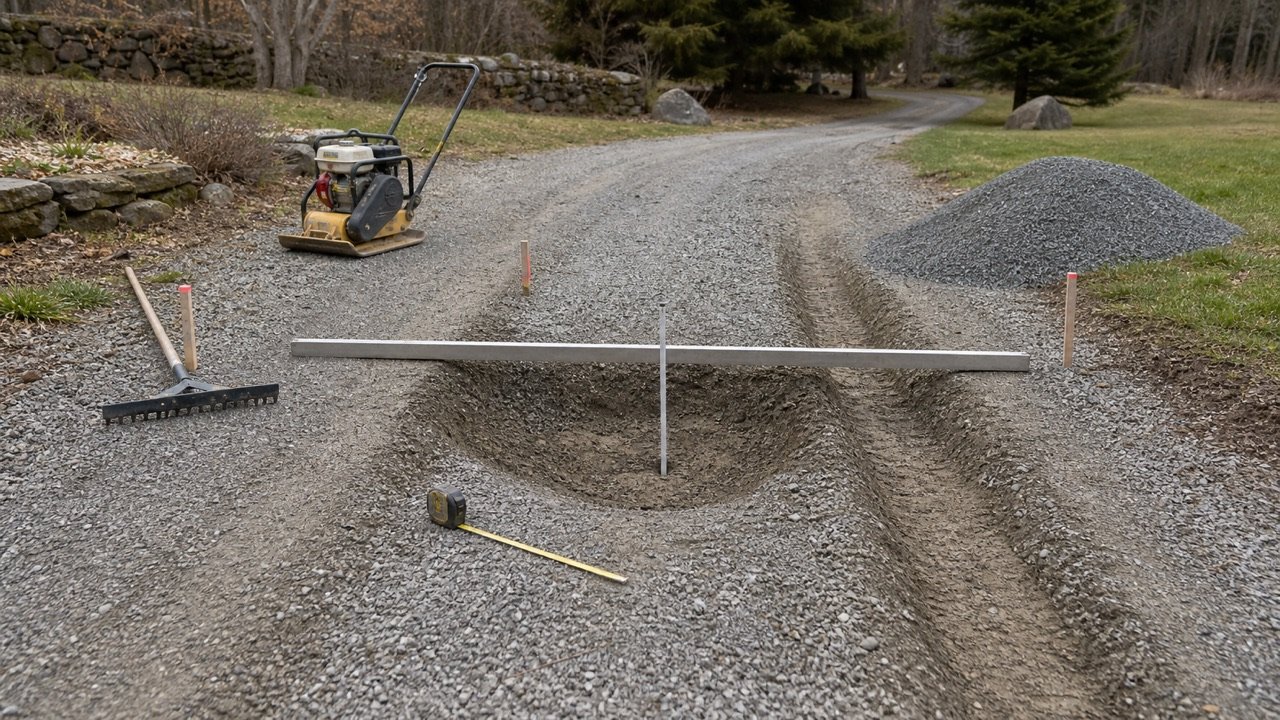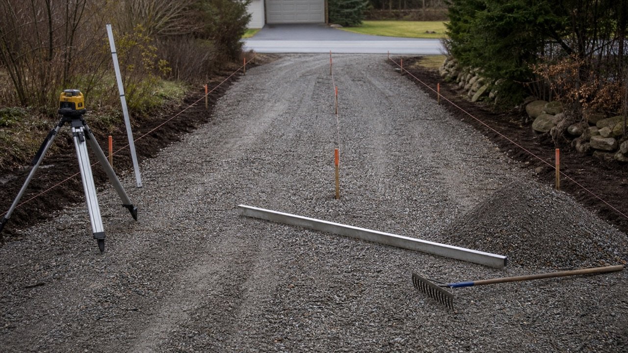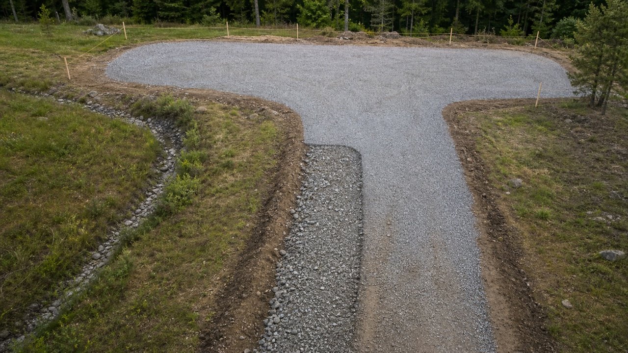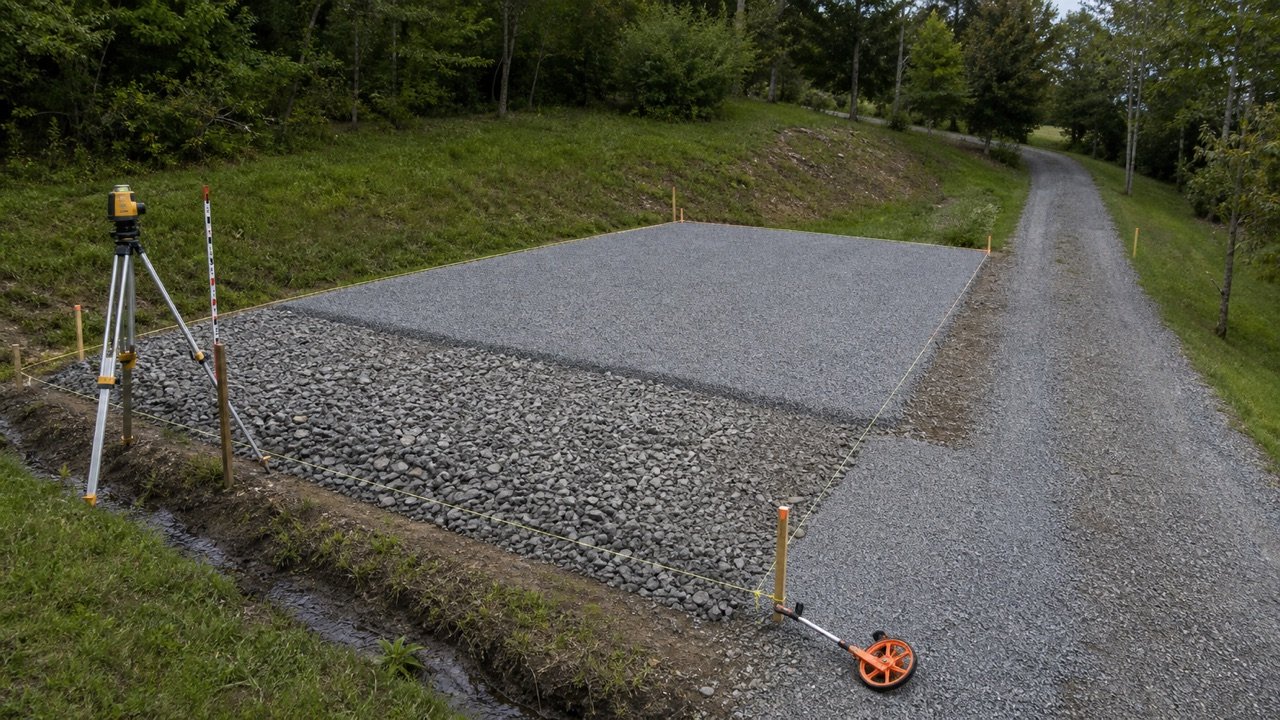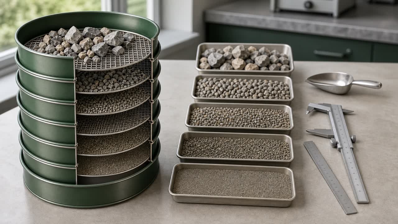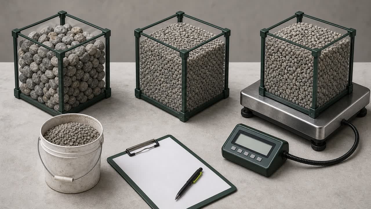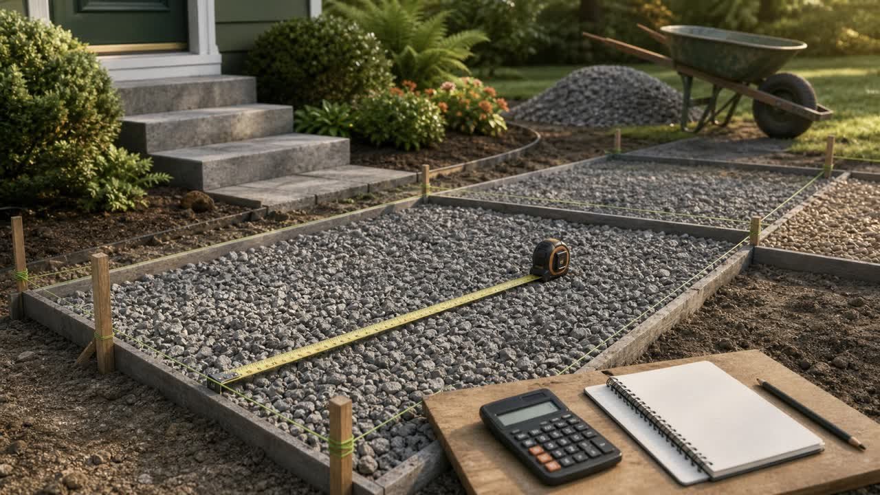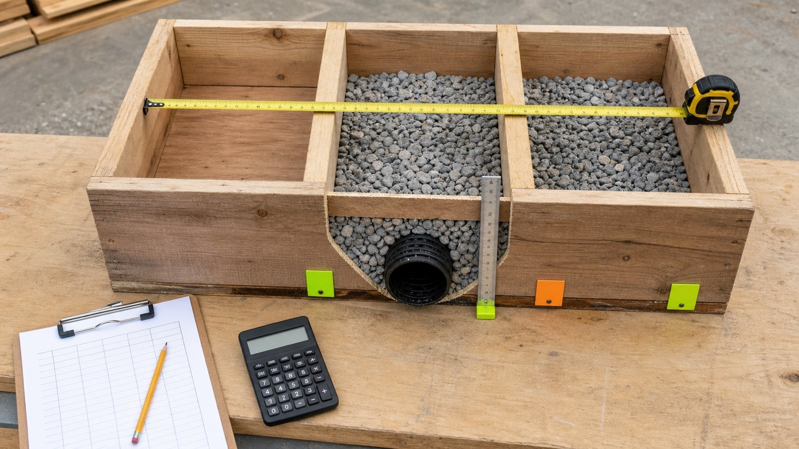
A drainage-gravel takeoff starts with the space that the selected gravel will occupy. Mark that boundary on the detail or field sheet before measuring length, width or depth.
Keep the full excavation, gravel zone, pipe, soil backfill, surface restoration and separate bedding products on different quantity lines. Their limits often differ.
What measurements do you need for drainage gravel?
Record the gravel-zone route length, inside width and total placed depth. Pair width and depth at the same station. Record the pipe's actual outside diameter and the length that sits inside each measured section.
Use the Drainage Gravel Calculator for one constant rectangular zone. Split a changing route into sections and add the unrounded net volumes.
The excavation may include overbreak, side slopes, shoring space, another bedding product or soil backfill. Include only the space assigned to this drainage gravel.
Which records should you collect before measuring?
| Record | What to take from it | Check |
|---|---|---|
| Drainage plan | Route, branches, pits, outlet and station limits | Current revision and units |
| Cross-section or detail | Gravel bottom, top, width and separate materials | Correct location and condition |
| Profile or levels | Bottom and top elevations along the run | Datum, station and design status |
| Pipe schedule or submittal | Product and actual outside diameter | Accepted product and size |
| Field measurement sheet | As-dug widths, levels and change points | Method, date and safe access |
| Supplier record | Product, selling unit and order increment | Current quote and material state |
The NRCS national Subsurface Drain standard page directs users to local technical guidance for planning, design and installation. The quantity sheet records an already selected detail; it does not choose the route, section or outlet.
Where does the gravel zone start and stop?
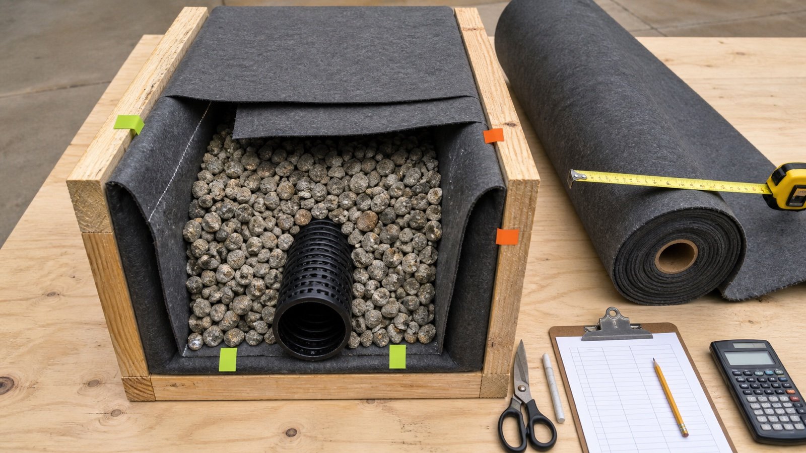
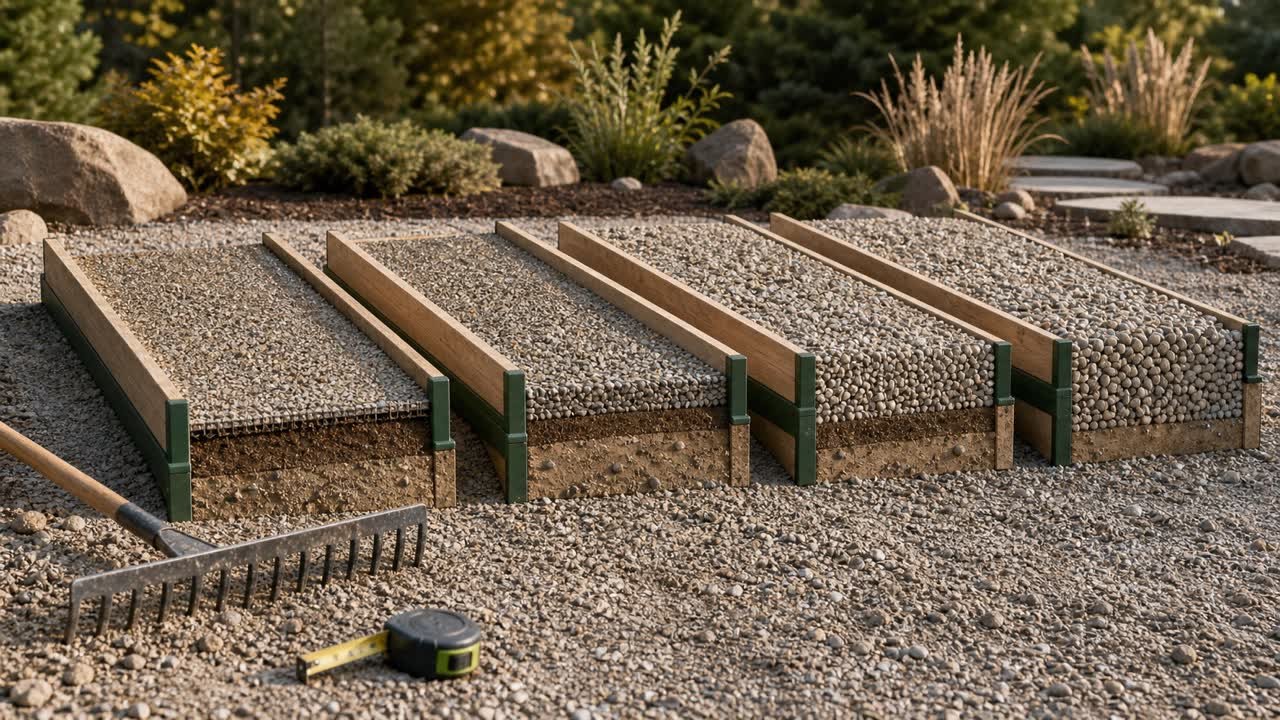
Trace the bottom, sides and top of the selected gravel on the approved cross-section. Use those limits for width and depth. A topsoil cap or final soil cover sits outside the gravel depth unless the detail labels it as the same product.
A gravel bed, haunch, surround and upper pipe zone may use one product or several products. The bedding and pipe-zone guide shows how to preserve each material boundary.
| Space | Use in this gravel measurement |
|---|---|
| Selected gravel zone | Include its measured inside dimensions |
| Pipe inside that zone | Deduct its documented outside volume |
| Different bedding or surround product | Calculate on another line |
| Excavation overbreak or working space | Exclude unless the same gravel will fill it by approved direction |
| Soil backfill and surface restoration | Keep outside the gravel quantity |
| Pit, basin or outlet structure | Use its own geometry and component deductions |
How should the route length be measured?
Measure along the route occupied by the constant gravel section. A curved drain needs its route length, not the straight chord between its ends. Record start and end stations so another person can locate the same limits.
Stop a section at every branch, pit, abrupt width or depth change, pipe-size change, different gravel product or change from pipe to no pipe. A long route can contain several short quantity sections.
A profile may provide horizontal station distance while the pipe follows a grade. Use the length basis required by the project record. State whether the entered length is plan length, slope length or measured installed length instead of switching between them.
How should width and depth be measured at stations?
Choose stations that capture the start, end and every change in cross-section. Take width and depth as a pair at each station. Add closer stations where the walls or levels change quickly.
Measure inside gravel width between the selected gravel boundaries. Derive gravel depth from its bottom and top levels, or measure it with a method approved for the work. Keep the datum and units beside every level reading.
| Station | Gravel width | Gravel depth | Gross area | Change note |
|---|---|---|---|---|
| 0 m | 0.45 m | 0.55 m | 0.2475 m2 | Section start |
| 4 m | 0.50 m | 0.60 m | 0.3000 m2 | Wider and deeper |
| 8 m | 0.42 m | 0.52 m | 0.2184 m2 | Narrow section |
| 12 m | 0.48 m | 0.58 m | 0.2784 m2 | Section end |
Use remote survey, a grade rod, laser, protected edge method or drawing dimensions where entry is unsafe or unauthorized. OSHA requires excavation hazard planning, utility checks, safe access, water controls, protective systems where applicable and competent-person inspections for covered U.S. work.
Why should width and depth stay paired?
A width and depth taken at one station describe one cross-section. Multiplying the average of all widths by the average of all depths can pair measurements that never occurred together.
Suppose a route has 2 stations: 0.40 m wide by 0.80 m deep, then 0.80 m wide by 0.40 m deep. Each station area is 0.32 m2, so the average paired area is 0.32 m2. The independent averages are 0.60 m wide and 0.60 m deep, which produce 0.36 m2. That method overstates the average section by 12.5%.
Calculate each station area first. Then use the measured areas to estimate the volume between stations.
How is a changing drainage-gravel section calculated?
For a rectangular section at each station, multiply paired width by paired depth. Estimate each segment from its start and end areas, then add the unrounded segment volumes.
Station area = inside gravel width x total gravel depth
Segment gross volume = segment length x (start area + end area) / 2
Pipe displacement = pi x (actual OD / 2)^2 x included pipe length
Net placed gravel = total gross segment volume - pipe displacement
The end-area method approximates the space between measured stations. An abrupt step, curved wall, shaped bed or irregular excavation may need another geometric model, surveyed sections or more station readings.
Worked example: changing metric trench section
A 12 m drainage route uses the station ledger above. One accepted pipe with 110 mm actual OD runs through the full section.
- 0 to 4 m: 4 x (0.2475 + 0.3000) / 2 = 1.0950 m3.
- 4 to 8 m: 4 x (0.3000 + 0.2184) / 2 = 1.0368 m3.
- 8 to 12 m: 4 x (0.2184 + 0.2784) / 2 = 0.9936 m3.
- Gross gravel-zone volume: 1.0950 + 1.0368 + 0.9936 = 3.1254 m3.
- Pipe displacement: pi x 0.055^2 x 12 = 0.1140 m3.
- Net placed gravel: 3.1254 - 0.1140 = 3.0114 m3.
The 3.0114 m3 result is geometric placed volume. Convert it to a supplier order only after documenting the exact gravel product, material states, supplier unit and rounding rule.
Worked example: constant imperial trench section
A constant gravel zone is 60 ft long, 16 in wide and 18 in deep. One full-length pipe has a checked 4.5 in outside diameter.
- Gross zone: 60 x (16 / 12) x (18 / 12) = 120 ft3, or 4.444 yd3.
- Pipe displacement: pi x (4.5 / 12 / 2)^2 x 60 = 6.627 ft3, or 0.245 yd3.
- Net placed gravel: 4.444 - 0.245 = 4.199 yd3.
NIST Handbook 44 Appendix C supports the exact inch, foot and yard relationships used in the conversion. It does not provide a gravel density or order allowance.
Which pipe dimension belongs in the record?
Use actual outside diameter for the accepted pipe product. Nominal size can describe a product series and may differ from the outside dimension that occupies gravel space.
Record the pipe product, actual OD source, included length and section limits. The pipe outside diameter guide explains the distinction and source checks.
Deduct only the pipe length inside the measured gravel section. Split a pipeless part, a pipe-size change or a partial run onto another line. Branch fittings, chambers, couplers and outlet structures need their documented geometry when their volume matters.
Should planned and as-dug measurements be mixed?
Keep planned, as-dug and installed records as separate states. A planned takeoff supports ordering. An as-dug check records the accepted open geometry. An installed record can reconcile pipe, gravel and approved changes.
| State | Source | Use |
|---|---|---|
| Planned | Current drawing, profile and detail | Baseline quantity and procurement |
| As-dug | Safe survey or accepted field measurement | Overbreak and section-change check |
| Installed | Placement, delivery and approved change records | Reconciliation and as-built record |
Do not quietly replace a planned dimension with one field reading. Record the station, reason, approval status and quantity effect of the change.
Which conditions need another method?
| Condition | Action |
|---|---|
| Shaped bed or partial haunch | Use the approved section geometry rather than a full rectangle |
| Multiple pipes | Record each OD, position and included length from the detail |
| Branch or junction | Stop clear run lengths and calculate the junction separately |
| Pit, basin or chamber | Use its solid shape and component deductions |
| Curved or irregular trench | Use closer stations, surveyed sections or a checked model |
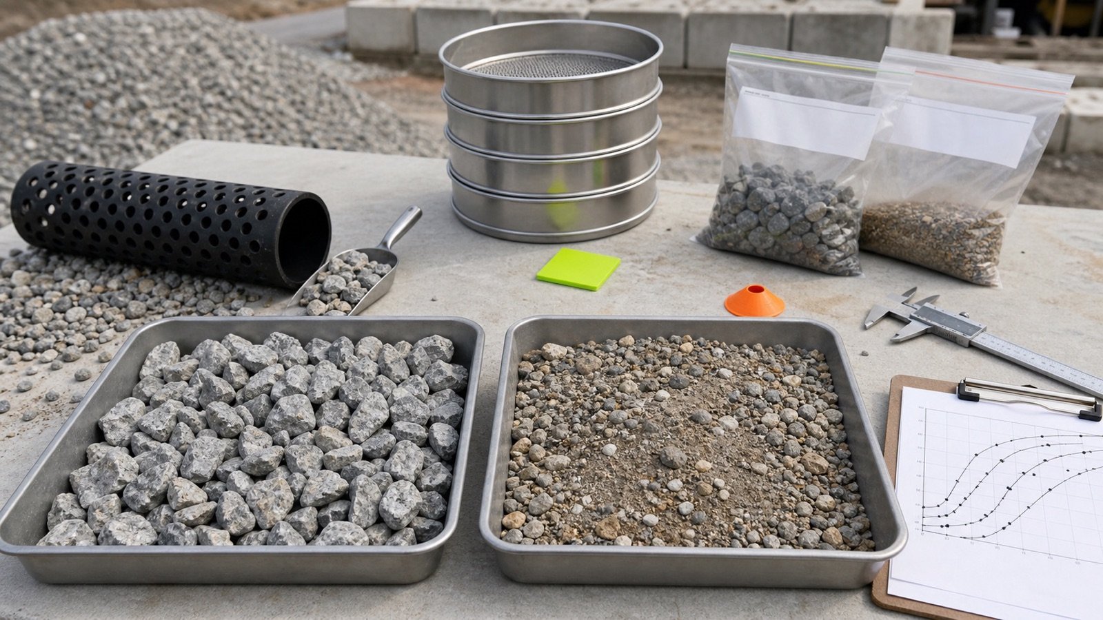
| Different gravel products | Split the material boundary and order lines |
| Unknown overbreak | Preserve the design baseline and record accepted field change separately |
What measurement mistakes change the gravel quantity?
- Using full excavation depth when gravel stops below the surface.
- Measuring width at one location and depth at another without paired stations.
- Multiplying independent average width and depth across a changing route.
- Using a straight end-to-end distance for a curved drain.
- Running one section through a branch, pit or abrupt change.
- Using nominal pipe size instead of actual outside diameter.
- Deducting full-length pipe volume from a partial pipe run.
- Mixing planned and as-dug dimensions without a revision record.
- Rounding every short segment before adding the product total.
- Entering an excavation to measure without required controls and authorization.
What design and safety limits still apply?
This method measures gravel for a selected section. It does not size the drain, choose a pipe or gravel, set grade, confirm filter compatibility, approve an outlet or establish hydraulic capacity.
NRCS directs users from its national standard to applicable local technical guidance. FHWA drainage guidance also ties excavation and bedding details to plans, pipe and site conditions. Use the drawings, local requirements, manufacturer information and responsible project people that govern the work.
For covered U.S. workplaces, OSHA identifies cave-ins, utilities, water, access and changing conditions among excavation hazards. Use the required competent-person and protective-system process. Other jurisdictions may set different or stricter controls.
Use the Trench Excavation Calculator for gross excavation, and keep that result separate from the drainage-gravel zone. The Gravel Planning hub lists related tools and field records.
Sources and source scope
- NRCS Subsurface Drain (Ft.) (606): national practice-standard record and local-guidance boundary.
- FHWA Drainage Guidelines: excavation, pipe bedding and granular-support review context.
- OSHA Trenching and Excavation eTool: U.S. excavation hazard planning, utility, access, water and inspection context.
- NIST Handbook 44 (2026), Appendix C: exact inch, foot, yard and SI conversion relationships.
Source scope: NRCS and FHWA support the need for project and local technical details. OSHA supports the stated U.S. workplace hazards. NIST supports unit conversions. None of these sources supplies a universal trench size, pipe selection, gravel depth, density or order allowance.
Review note: Saleem Sial owns the research and editorial record. Source checks, independent fixtures, editorial review, build validation, link crawl, schema review and rendered QA form the internal publication gate. Waseem Sial, External Reviewer and Engineer, is listed for ongoing external review; no completed review date is claimed.