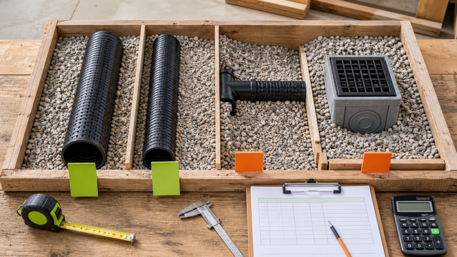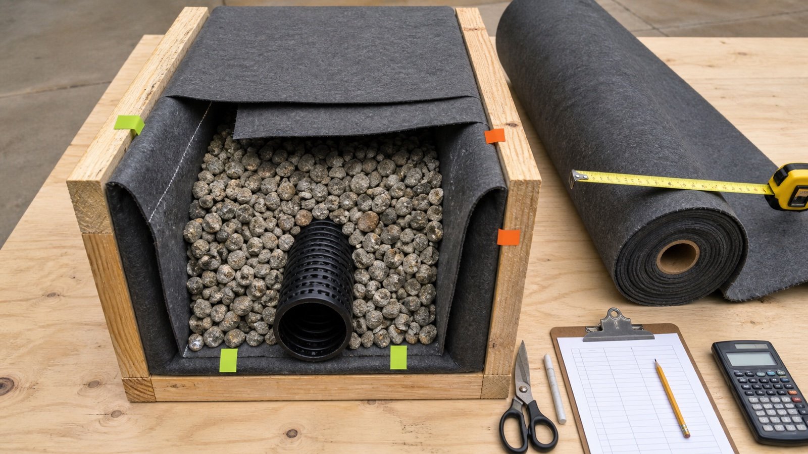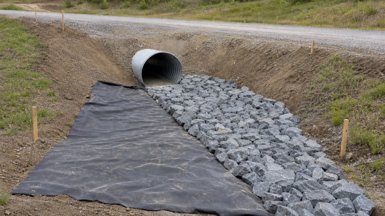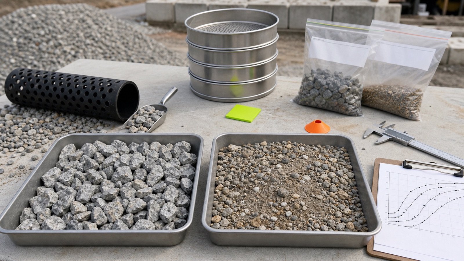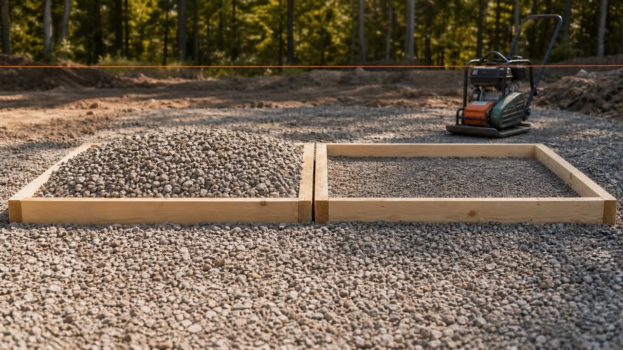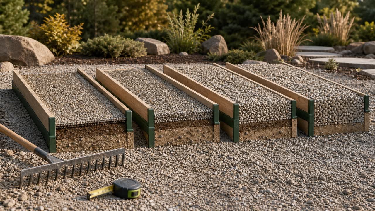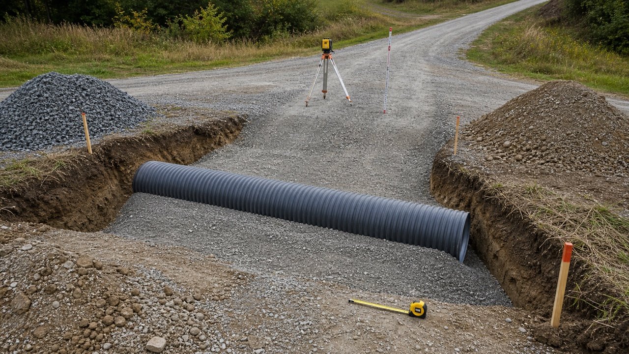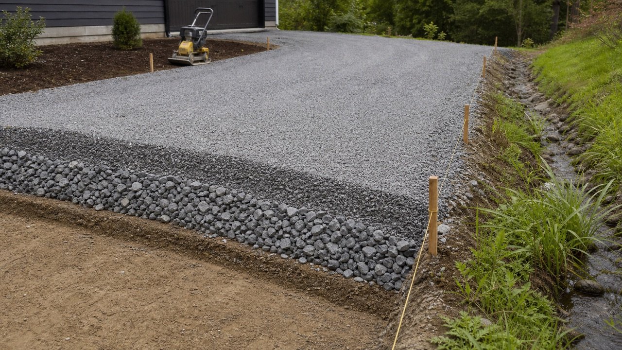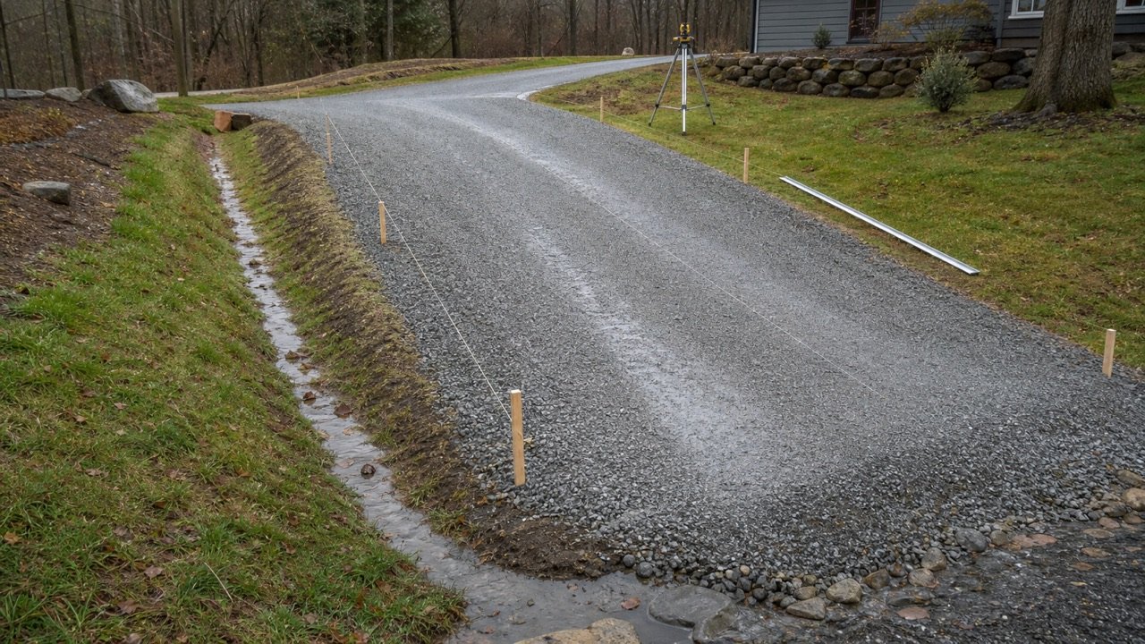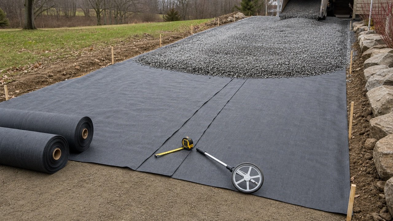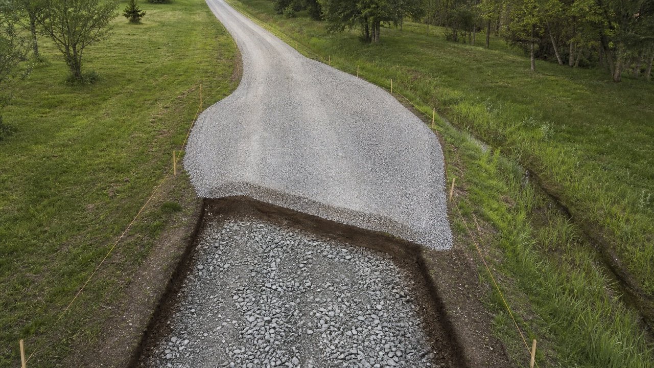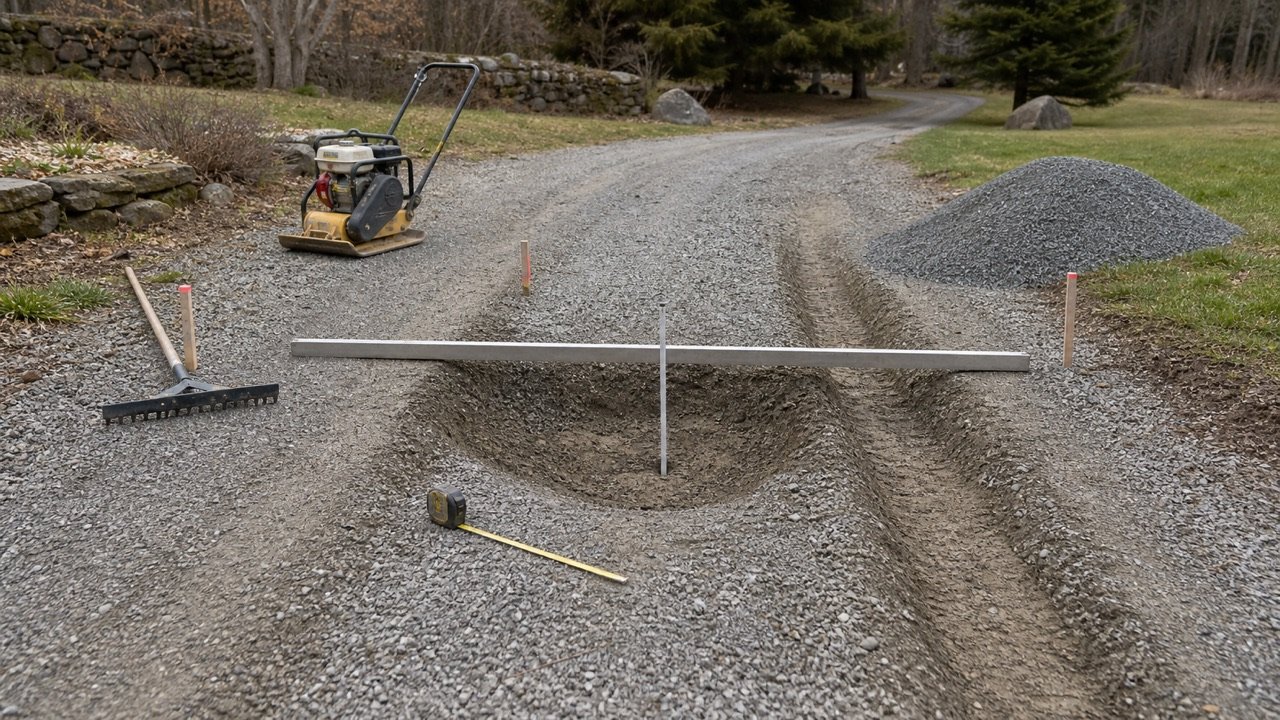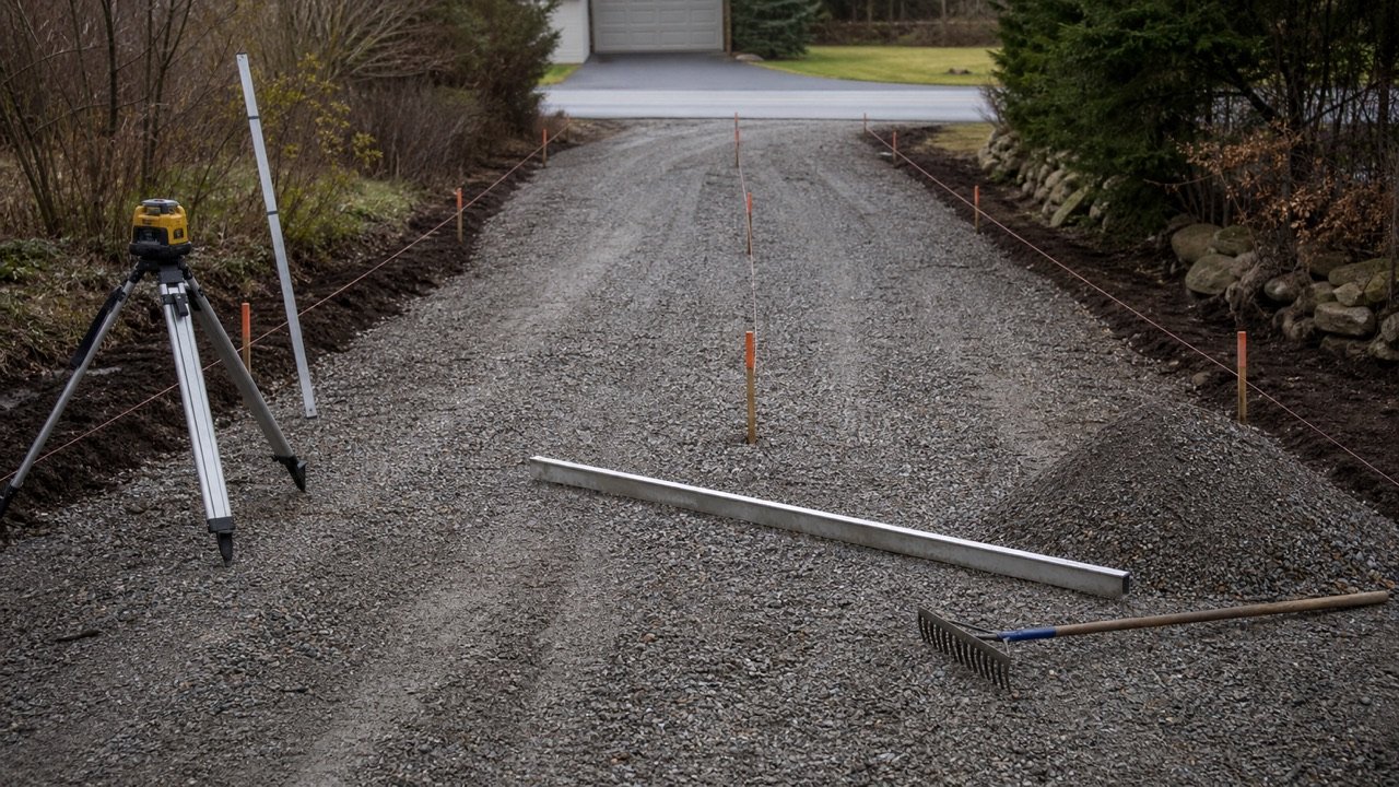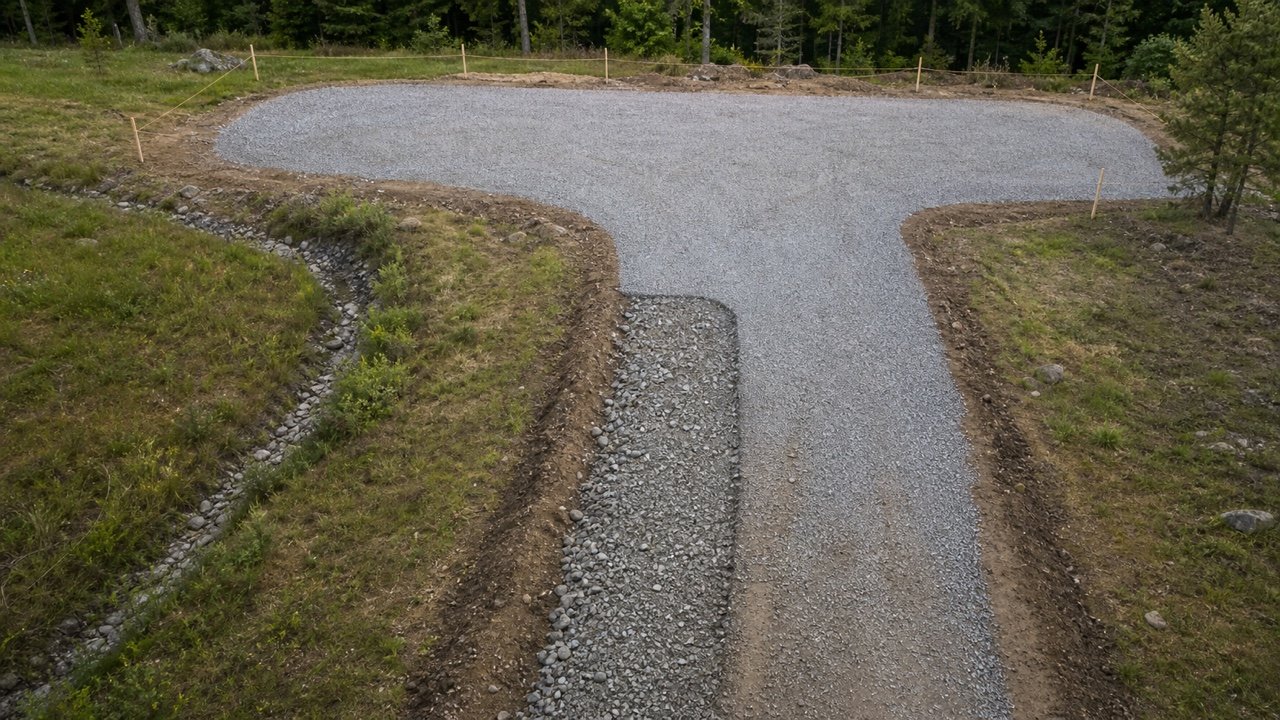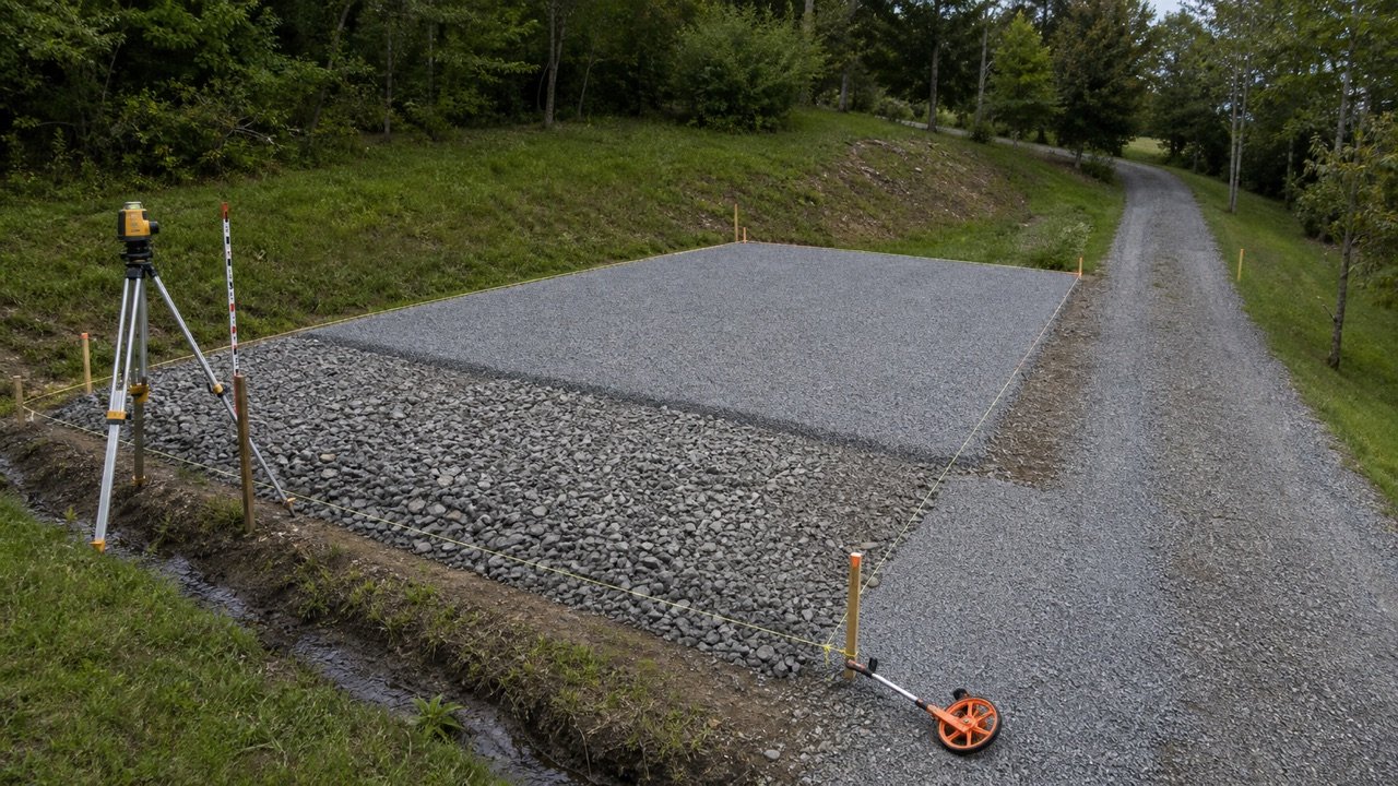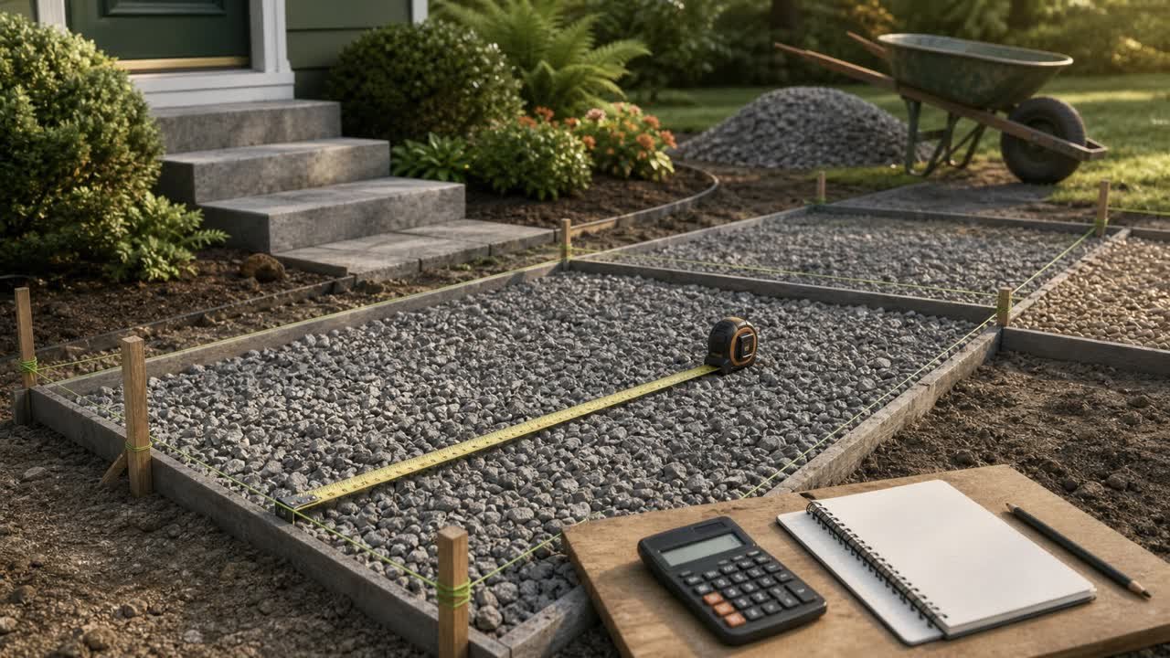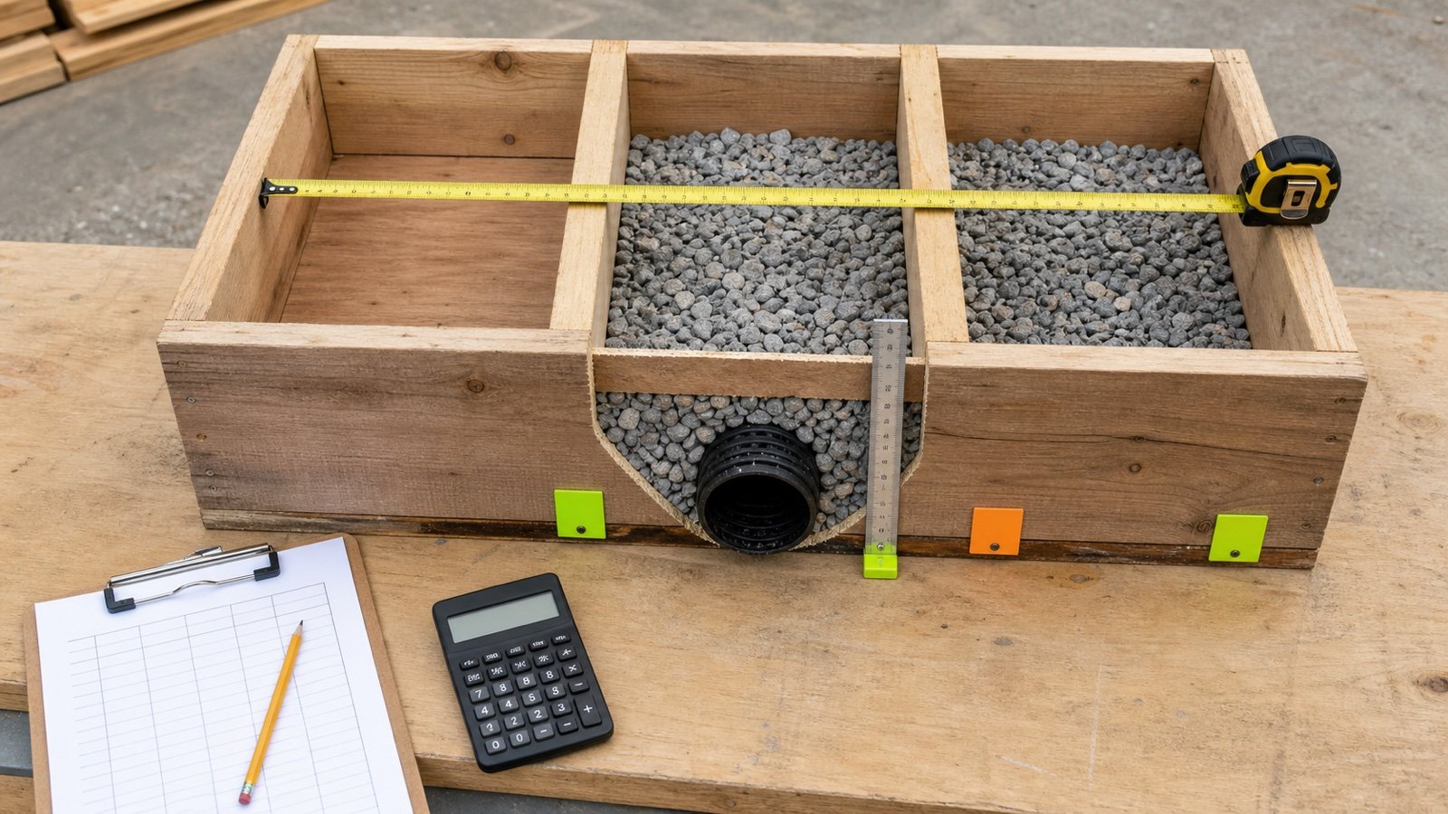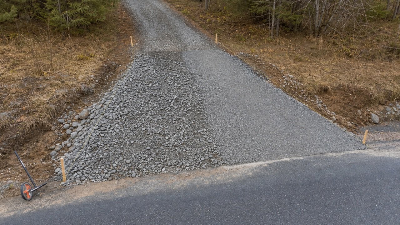
A gravel driveway apron widens the private drive where it meets a road, curb, shoulder, sidewalk, or right-of-way line. Its takeoff needs the approved approach limits, flare geometry, levels, layer schedule, drainage interfaces, and road-authority requirements.
Measure excavation, subbase, base, surface gravel, geotextile, culvert work, shoulder restoration, and pavement tie-in as separate items. Their footprints and material states often differ within a short approach.
How do you calculate gravel for a driveway apron?
Calculate each approved layer's net plan area, multiply by its accepted compacted thickness, and convert the result to cubic yards or cubic metres. A straight-sided flare is a trapezoid, so its area uses the average of the throat width and road-end width.
Flared apron area = length × (throat width + road-end width) ÷ 2
Cubic yards = area in square feet × compacted depth in inches ÷ 324
Cubic metres = area in square metres × compacted depth in millimetres ÷ 1,000
Repeat the calculation for each layer and footprint. Keep the compacted geometric result separate from loose delivery volume, supplier mass, handling allowance, and selling-unit rounding.
For a centered straight-sided apron whose edges change at a constant rate, use the Driveway Gravel Calculator in uniform-taper mode and enter the approved base and surface depths separately. Use the sectioned methods below when the apron is asymmetric, curved, stepped, changes depth, or has different layer footprints.
This method measures an approved driveway approach. It does not choose the access location, width, flare, radius, grade, sight distance, pavement section, culvert, drainage route, sidewalk treatment, or permit conditions.
Where does the apron start and end?
Use the limits named by the governing plan, permit, or road authority. The apron may extend from a curb or road edge to a right-of-way line, sidewalk edge, property line, or another defined construction joint.
Prince George's County, for example, defines its driveway apron from the curb to the county road right-of-way limit. Another jurisdiction can use different limits, materials, and approval steps.
| Boundary | Evidence | Quantity effect |
|---|---|---|
| Private-drive throat | Approved width, station, and tie-in line | Sets the narrow end of the flare |
| Road end | Edge of pavement, curb, gutter, shoulder, or named baseline | Sets apron length and wide-end width |
| Right-of-way | Survey, permit, or authority plan | Separates public and private work or measurement records |
| Sidewalk or path | Approved pedestrian-route limits and levels | Creates a separate surface, restoration, or exclusion |
| Ditch or culvert | Drainage plan, pipe ends, headwalls, and protection limits | Splits the apron around drainage structures |
| Road repair | Sawcut, patch, shoulder, or curb-replacement limits | Adds materials with different specifications and units |
Do not use the visible gravel edge as a legal or contract boundary. Existing material can spread beyond the approved footprint, while a right-of-way or pavement-repair limit may be invisible on site.
Which documents and measurements are needed?
Start with the current permit, plan, profile, cross-sections, road-authority detail, drainage plan, layer schedule, specification, and selected supplier data. Record every revision used for the takeoff.
- Apron length, throat width, road-end width, left and right flare limits, and any curve or radius.
- Road edge, shoulder, curb, gutter, sidewalk, property, right-of-way, and construction-joint locations.
- Existing ground, prepared surface, road edge, gutter, sidewalk, driveway, and finished-apron levels.
- Excavation, undercut, geotextile, subbase, base, surface, and restoration limits.
- Accepted compacted thickness and specification for every aggregate layer.
- Ditch, culvert, headwall, end section, utility, sign, mailbox, and other exclusions.
- Supplier product, bulk density or yield, material state, selling unit, minimum order, increment, and quote date.
TxDOT driveway-profile guidance shows why the profile belongs in the source pack: roadway cross-slope, driveway grade, vertical transitions, curb and gutter, drainage, and right-of-way conditions can control the approved shape.
How is a centered flared apron area calculated?
Use a trapezoid when both side edges change in straight lines over the same apron length. Measure length perpendicular to the road baseline or by the baseline stated in the drawing.
A = L × (Wt + Wr) ÷ 2
Here, L is apron length, Wt is throat width, and Wr is road-end width. The same formula works for a centered or off-center trapezoid when both flare edges span the same length and do not cross.
| Shape | Method | Use condition |
|---|---|---|
| Rectangle | Length × width | Both edges remain parallel and width is constant |
| Straight flare | Length × average of end widths | Both edges are straight over one common length |
| Throat plus 2 wings | Throat rectangle + left triangle + right triangle | Left and right flare widths are measured separately |
| Different wing lengths | Calculate each wing with its own perpendicular length | One flare begins before the other |
| Curved or irregular edge | Surveyed polygon, checked CAD area, or short measured segments | A straight trapezoid does not match the approved boundary |
A diagonal tape between unmatched corners does not prove perpendicular apron length. Check the baseline, offsets, and corner coordinates before using the trapezoid formula.
How is an asymmetric flare measured?
Split an asymmetric apron into the throat rectangle and separate flare triangles. This keeps the left and right road connections visible in the worksheet.
Area = L × Wt + (L × fL ÷ 2) + (L × fR ÷ 2)
The variables fL and fR are the added widths at the road end. This formula assumes both wings span the same perpendicular length L. Use each wing's own height when the flare start points differ.
Keep islands, curb returns, headwalls, retained pavement, or other excluded shapes outside the gross triangles. Show each deduction as a named polygon or measured area.
Why should every layer have its own footprint?
The excavation, geotextile, base, surface gravel, shoulder, and pavement patch can start or stop at different lines. A single apron area can misstate several materials at once.
| Zone | Measure | Keep separate because |
|---|---|---|
| Clearing or surface removal | Approved disturbance area and material type | Grass, existing gravel, pavement, and topsoil need different handling |
| Excavation | Existing surface to approved formation | Depth can change toward the road and across the ditch |
| Undercut replacement | Accepted weak-zone limits after inspection | It may extend beyond or below the normal section |
| Geotextile | Specified surface plus approved panels, overlaps, and returns | Roll layout differs from aggregate volume |
| Subbase or base | Its own net footprint × compacted thickness | The structural footprint can extend beyond the visible surface |
| Surface gravel | Finished gravel footprint × accepted compacted thickness | It may stop before a paved road tie-in or curb return |
| Shoulder or ditch restoration | Separate plan or section limits | Product, compaction, vegetation, and pay unit can differ |
| Road patch or curb work | Authority-defined cut and replacement limits | Road materials and inspection rules differ from private gravel |
The gravel driveway layer guide explains how to keep accepted compacted depths and material specifications separate.
Worked imperial example
An approved straight apron is 15 ft long. It widens from a 12 ft driveway throat to 24 ft at the road. The same 270 ft² footprint has an 8 in compacted base and a 2 in compacted surface layer.
| Quantity | Calculation | Result |
|---|---|---|
| Plan area | 15 × (12 + 24) ÷ 2 | 270 ft² |
| Compacted base | 270 × 8 ÷ 324 | 6.666667 yd³ |
| Compacted surface | 270 × 2 ÷ 324 | 1.666667 yd³ |
| Total compacted aggregate geometry | 6.666667 + 1.666667 | 8.333333 yd³ |
The combined total checks the 10 in aggregate section, but the supplier record still needs 2 separate products. No density, loose-volume conversion, handling allowance, or selling increment has been applied.
Worked metric example
A second approved apron is 5 m long and widens from 3.6 m to 7.2 m. It has a 200 mm compacted base and a 50 mm compacted surface layer over the same footprint.
| Quantity | Calculation | Result |
|---|---|---|
| Plan area | 5 × (3.6 + 7.2) ÷ 2 | 27.000000 m² |
| Compacted base | 27 × 200 ÷ 1,000 | 5.400000 m³ |
| Compacted surface | 27 × 50 ÷ 1,000 | 1.350000 m³ |
| Total compacted aggregate geometry | 5.400000 + 1.350000 | 6.750000 m³ |
Use the unrounded layer volumes for later conversion. The 6.75 m³ total does not establish the delivered loose volume or mass.
How is excavation calculated when width and depth both change?
Use the integrated linear-width and linear-depth formula when straight apron edges widen at a constant rate and excavation depth also changes at a constant rate along the same baseline.
V = L ÷ 6 × (2w0d0 + w0d1 + w1d0 + 2w1d1)
In the imperial example, width changes from 12 ft to 24 ft while excavation depth changes from 0.50 ft at the throat to 0.25 ft at the road.
V = 15 ÷ 6 × [(2 × 12 × 0.50) + (12 × 0.25) + (24 × 0.50) + (2 × 24 × 0.25)] = 97.500000 ft³ = 3.611111 yd³
Multiplying 270 ft² by the 0.375 ft average depth gives 101.25 ft³. That shortcut overstates this fixture because the greater depth occurs at the narrower end.
For the metric example, depths of 0.22 m and 0.10 m return 4.140000 m³. Plan area times average depth returns 4.320000 m³ and fails the same check.
Use this equation only when width and depth change linearly along one shared baseline. Crossfall breaks, curved edges, stepped excavation, undercut pockets, and ditch transitions need shorter zones, cross-sections, survey, CAD, or a checked model.
How are curved flare edges or curb returns measured?
Use the approved curve geometry or a surveyed boundary. A guessed radius can produce a polished area that does not match the permitted edge.
- Record tangent points, center, radius, offsets, and baseline from the plan when they are fully defined.
- Check whether the curve marks the gravel edge, curb face, back of curb, pavement cut, or another boundary.
- Measure the actual net polygon or surface in CAD when a digital design is available.
- For field work, collect enough offsets or coordinates to represent the approved curve within the required tolerance.
- Keep left and right curves separate where their radii, tangent points, or obstructions differ.
Do not force a curved approach into one average width unless the project's measurement rule permits that approximation and its tolerance is recorded.
How are culverts, ditches and drainage kept out of the apron total?
Overlay the apron footprint with the approved drainage limits, then measure every material interface once. The driveway surface can cross above a culvert while the ditch, end protection, and road shoulder use different quantities.
- Subtract a headwall, end section, curb, gutter, or retained pavement only from the layer it physically displaces.
- Keep pipe bedding and trench backfill outside the apron-layer lines unless the approved section combines them.
- Measure riprap, geotextile, side-slope protection, and toe treatment from their own surfaces and sections.
- Keep ditch regrading, topsoil, seed, erosion control, and outlet work separate from driveway aggregate.
- Check that finished gravel does not block the approved gutter, ditch, culvert opening, or road drainage path.
Use the driveway culvert quantity guide for the crossing and the culvert end-protection guide for riprap and filter zones.
How should a sidewalk or pedestrian route be handled?
Preserve the approved pedestrian-route surface, width, cross-slope, grade, joints, and transition details. Treat sidewalk removal and replacement as its own item unless the authority detail combines it with the approach.
The U.S. Access Board explains how landings and flares affect accessible routes in the standards it covers. The governing road and accessibility documents decide which rules apply to a specific driveway.
Do not use the gravel flare area as the sidewalk quantity. Concrete, asphalt, pavers, detectable surfaces, joints, reinforcement, base, and restoration each need the approved limits and units.
How is compacted geometry converted into an order?
Convert each material after the compacted geometry is complete. Use product-specific evidence that matches the selected aggregate and the state in which the supplier sells it.
- Sum each approved layer and footprint without early rounding.
- Deduct accepted reusable material only in a compatible material state.
- Use a documented loose-to-compacted relationship when the order is by loose volume.
- Use a supplier, quarry, specification, or test bulk density when the order is by mass.
- Add a handling allowance as a separate line when site evidence supports it.
- Round once to the supplier's selling increment.
- Confirm legal payload, delivery access, unloading position, partial-load policy, fees, and quote expiry.
Do not use particle density or specific gravity as bulk density. The placed aggregate contains voids, and moisture or gradation can change bulk mass. The Gravel Calculator can check an approved uniform layer, while the gravel cost guide records current supplier pricing and delivery terms.
Which site conditions need a new decision?
Pause the quantity takeoff when field conditions or proposed work do not match the approved approach. A larger quantity cannot correct an unresolved access, drainage, profile, or safety issue.
| Condition | Quantity effect | Decision needed |
|---|---|---|
| Public right-of-way work | Permit, material, inspection, traffic control, and contractor rules can apply | Confirm the road authority's current approval and limits |
| Changed road edge or shoulder | Apron length, tie-in elevation, and restoration quantities change | Survey and revise the detail before ordering |
| Soft, wet, or pumping formation | Undercut, stabilization, drainage, or layer footprint may increase | Obtain the required subgrade decision and acceptance |
| Sidewalk, bike route, or curb ramp | Pedestrian surface and transitions add separate work | Use the approved accessibility and road detail |
| Culvert, ditch, or concentrated runoff | Pipe, excavation, protection, and outlet zones interrupt the apron | Coordinate the designed drainage crossing and approach |
| Heavy or unusual design vehicle | Width, turning path, profile, and pavement section can change | Use the vehicle and access design approved for the site |
| Utilities, signs, mailbox, or property conflict | Limits, excavation, relocation, or protection quantities change | Resolve ownership, location, clearance, and permit requirements |
FHWA access-management guidance treats driveways as roadway access points. Location and movement decisions belong to the road-safety and permitting process, not a gravel-volume formula.
Common apron quantity mistakes
- Using the private driveway width across the full apron and omitting the flares.
- Using one commercial calculator's standard width, depth, density, or compaction factor.
- Measuring to the visible gravel edge instead of the approved construction boundary.
- Treating a curved edge as a straight flare without checking the area difference.
- Using area times average depth when width and depth change together.
- Applying one footprint to excavation, geotextile, base, surface, shoulder, and road repair.
- Subtracting the full culvert or structure from layers it does not occupy.
- Combining road-authority work and private-drive work under one material line.
- Ignoring curb, gutter, ditch, sidewalk, or accessible-route restoration.
- Calling compacted geometry a loose delivered quantity.
- Using a universal tons-per-yard value or nominal truck capacity.
- Rounding each triangle or layer before the apron total is complete.
- Ordering before the road tie-in elevation and drainage path are accepted.
What should the field quantity record contain?
- Project, approach ID, road, side, location, date, weather, and existing surface condition.
- Permit, plan, profile, standard detail, specification, revision, and open clarification.
- Survey datum, baseline, throat, road-end, right-of-way, property, sidewalk, ditch, and pavement limits.
- Corner coordinates, offsets, flare lengths, widths, curve data, levels, and cross-sections.
- Gross and excluded areas for excavation, geotextile, base, surface, shoulder, and restoration.
- Accepted compacted thickness, product specification, material state, and geometry for every layer.
- Density or loose-conversion source, handling line, selling unit, order increment, and quote date.
- Delivery access, unloading location, payload check, traffic-control need, and inspection hold points.
- Measured by, checked by, field changes, approval status, and photographs.
Safety and scope
Confirm utility locations, road-work rules, traffic control, excavation conditions, equipment access, and public protection before work starts. OSHA trenching and excavation guidance identifies cave-ins and other hazards for US workplaces. Apply the rules and competent-person decisions required for the site.
This guide checks geometry and supplier quantities. It does not issue a permit, establish a property or right-of-way line, design access or pavement, approve a sidewalk, size drainage, locate utilities, or certify construction.
Sources and source scope
- Prince George's County, What is a driveway apron?: one authority's right-of-way definition and permit context.
- TxDOT Roadway Design Manual, Driveway Profiles: road cross-slope, approach grade, vertical transition, curb, gutter, drainage, and right-of-way design context.
- Washington County, Oregon, Road Design and Construction Standards: current local examples of separate curbed, uncurbed, residential, commercial, and private-road approach details.
- FHWA, Corridor Access Management: roadway access and safety context for driveways.
- U.S. Access Board, Chapter 4 Guide: landing and flare context where covered accessibility standards apply.
- NIST Guide to the SI, Appendix B.8: exact unit relationships used in the examples.
- OSHA, Trenching and Excavation: US workplace excavation-hazard scope.
Source scope: the agency pages show why apron limits, profiles, drainage, public access, and pedestrian interfaces require governing documents. They do not provide one universal gravel width, depth, density, flare, or order factor. The worked examples test arithmetic for stated hypothetical approved layouts.
For a centered straight-sided apron with one shared layer footprint, enter the approved depths in the Driveway Gravel Calculator. Check layer selection in the driveway layer guide, verify drainage with the crossfall and grade guide, calculate one uniform material layer with the Gravel Calculator, or return to the Gravel planning hub.