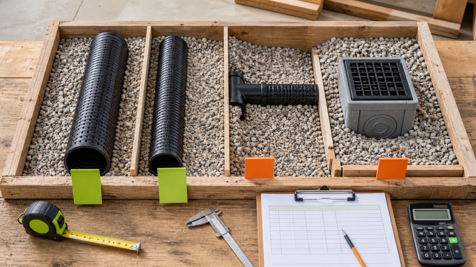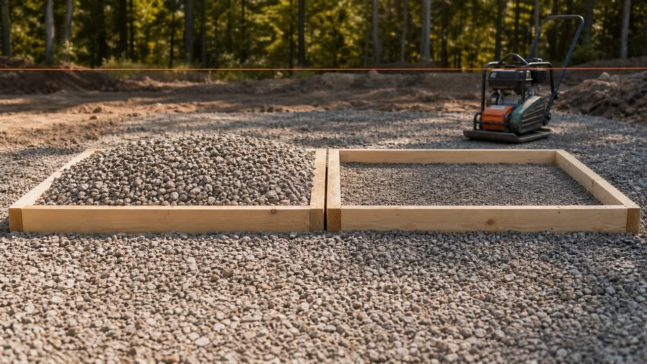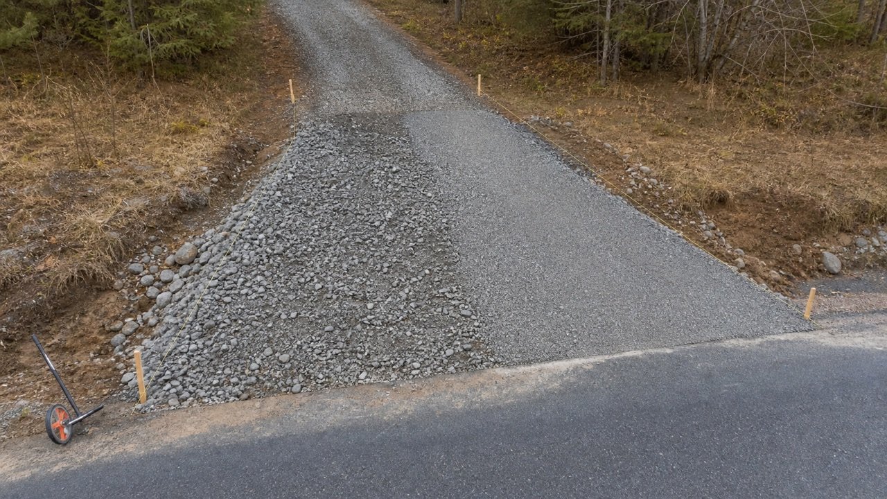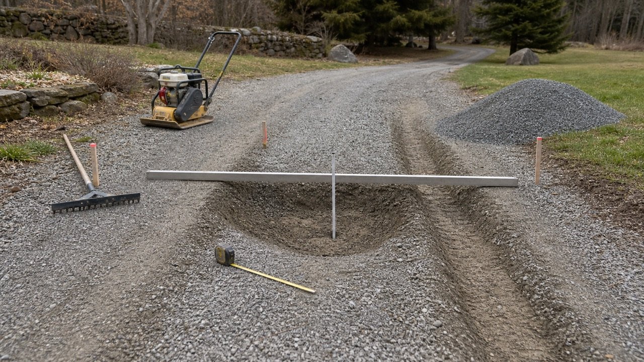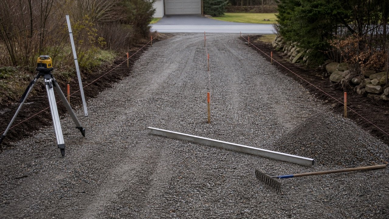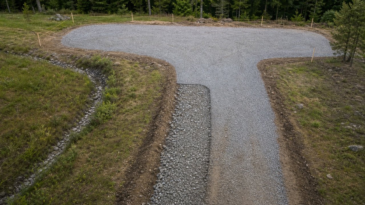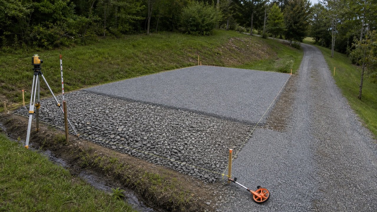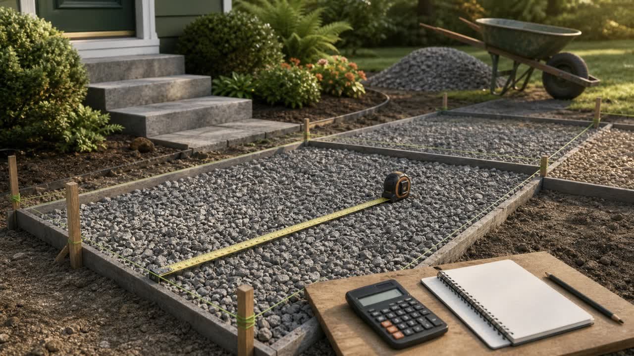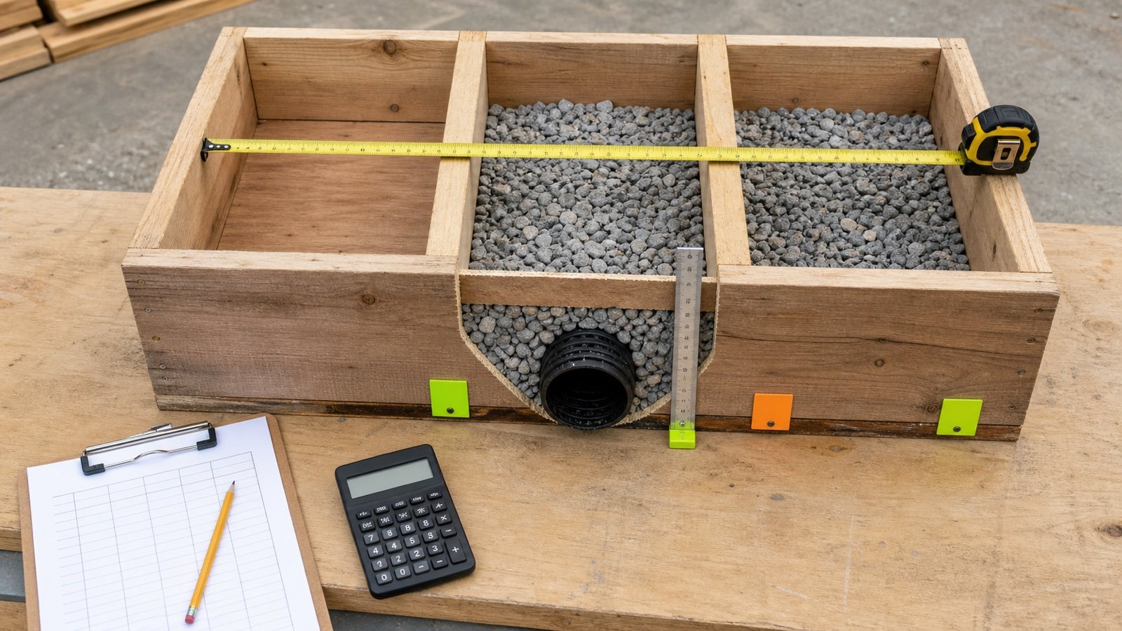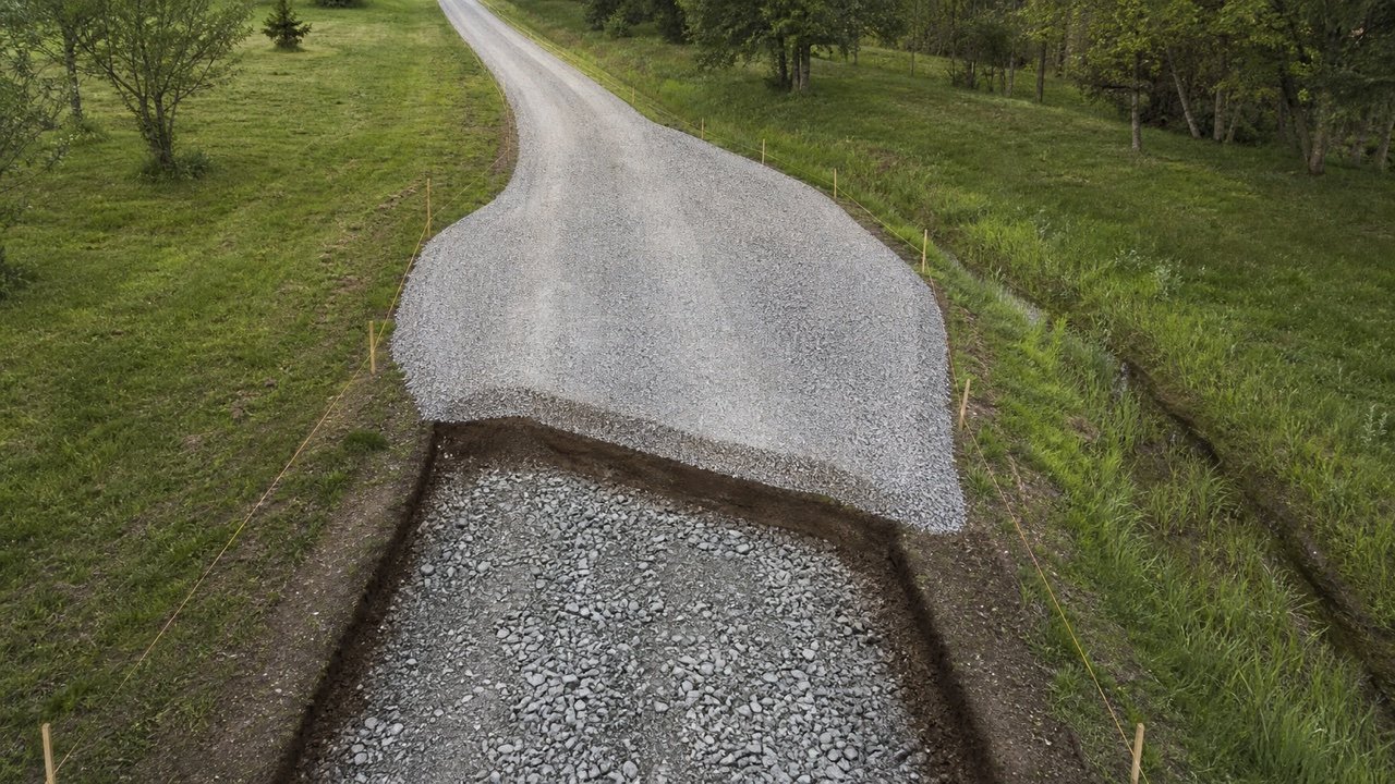
A gravel passing bay adds a controlled widening to a narrow driveway so approved vehicles can pass. Its quantity includes the full-width bay, the entry and exit tapers, and any reconstruction inside the existing driveway.
Measure the approved construction limits rather than treating the bay as one bounding rectangle. A rectangle around the full feature counts material outside both tapers and can conceal different layer, drainage, and grading boundaries.
How much gravel does a driveway passing bay need?
Multiply the added width by the parallel bay length, then add the area of each taper. Multiply that net area by the accepted compacted thickness of each gravel layer.
Net widening area = parallel bay area + entry taper area + exit taper area
Straight taper area = taper length × added width ÷ 2
Cubic yards = area in square feet × compacted depth in inches ÷ 324
Cubic metres = area in square metres × compacted depth in millimetres ÷ 1,000
This shortcut fits straight tapers that change evenly from zero added width to the full bay width. Use separate triangles, trapezoids, offsets, coordinates, or a checked drawing area for an asymmetric, curved, or offset layout.
The calculation measures a passing bay or turnout that has already been designed for the route and intended vehicles. It does not select the bay size, taper, location, interval, sight distance, pavement section, grade, drainage, traffic control, or emergency-access capacity.
Which measurements define the widening?
Record the retained driveway edge, the new outer edge, both taper endpoints, and the full-width bay endpoints. These 4 limits prevent the existing lane and widening from being counted together without a clear boundary.
| Measurement | Field or drawing evidence | Quantity use |
|---|---|---|
| Existing driveway edge | Accepted retained-construction line | Baseline for added width and overlap |
| Full added width | Perpendicular distance to the new outer edge | Bay rectangle and taper triangles |
| Parallel bay length | Distance between full-width taper points | Central rectangle area |
| Entry taper length | Distance along the original driveway baseline | First triangle or measured transition |
| Exit taper length | Distance along the original driveway baseline | Second triangle or measured transition |
| Layer and excavation limits | Approved pavement section and cross-sections | Separate area for every item |
| Formation levels | Survey, profile, crossfall, and grading plan | Cut, fill, and variable-depth quantities |
Measure taper length along the original driveway direction. Measure added width perpendicular to that baseline. Using a sloping outside edge as the taper length makes the triangle area too large.
Is a passing bay the same as a turnaround?
A passing bay lets vehicles clear each other along a narrow route. A turnaround lets a vehicle reverse its direction near a route end. Their location, operating envelope, and approved geometry serve different tasks.
Current local authority examples confirm that difference. San Miguel Fire & Rescue discusses turnouts at intervals along long access routes and a separate terminal turnaround. Mono County also lists roadway turnouts and turnarounds under different provisions.
| Feature | Function | Use the matching quantity record |
|---|---|---|
| Passing bay or turnout | Allow 2-way passage on a narrow route | Parallel widening and tapers |
| Terminal turnaround | Reverse travel direction | Circle, ring, hammerhead, T, or Y footprint |
| Parking pad | Store vehicles and provide maneuvering area | Parking, access, and layer zones |
| Road apron | Join a driveway to the public or private road edge | Flare, tie-in, culvert, and restoration limits |
The driveway turnaround quantity guide covers terminal movement geometry. Do not add its footprint to a passing bay unless both approved features exist.
Where do the turnout dimensions come from?
Use the governing authority, approved access plan, design vehicle, pavement design, and site documents. Current published rules show that triggers and dimensions change with jurisdiction, use, length, parcel count, grade, loading, and hazards.
San Juan County's current fire-access checklist uses one set of driveway and turnout requirements. San Miguel Fire & Rescue cites its 2026 code framework and another interval. Mono County publishes different turnout and driveway provisions. Highland Council's current private-access guidance includes service bays, turning areas, visibility, drainage, permits, and utilities.
These sources show the need for a local decision. Their dimensions must not be combined into an average or copied into an unrelated project.
- Record the authority, document title, revision, approval, and project application.
- Identify the vehicles that must pass and the clear operating envelope.
- Confirm sight distance in both directions and any vegetation-control zone.
- Locate the bay relative to curves, crests, gates, bridges, culverts, buildings, and property boundaries.
- Confirm surface, loading, grade, crossfall, drainage, and maintenance requirements.
- Keep parking, storage, snow, and landscape items out of the required clear area where the approval requires it.
How is a straight passing bay area calculated?
Calculate the full-width central section as a rectangle. Calculate each straight taper as a triangle when the widening changes evenly from zero to the full added width.
A = L × W + (T1 × W ÷ 2) + (T2 × W ÷ 2)
The tapers do not need equal lengths. Keep `T1` and `T2` separate when the approved geometry differs at each end.
Use the Driveway Gravel Calculator for each rectangular or uniformly tapered section when its base and surface layers share one footprint. Enter one section at a time, keep the unrounded results, and then sum matching products across the passing bay. Use the measured-area method below for curved boundaries, different layer footprints, retained-lane reconstruction, and overlap deductions.
A quick bounding check multiplies the added width by the combined taper and bay length. The calculated net widening must be smaller than that rectangle when either taper narrows to zero. For 2 full triangular tapers, the unused part of the bounding rectangle equals half of each taper rectangle.
How are curved or offset tapers measured?
Use offsets, coordinates, a surveyed polygon, or a checked digital area when a taper does not have straight sides. Short stations along the driveway can capture the changing width without forcing the boundary into one triangle.
| Layout | Area method | Main check |
|---|---|---|
| Different entry and exit taper lengths | 2 separate triangles | Each perpendicular length and full added width |
| Partial-width taper endpoints | Trapezoids | Start and end widths on the same baseline |
| Curved outer edge | Short offsets or surveyed polygon | Enough stations to follow the approved curve |
| Bay on a horizontal curve | Coordinates or checked CAD area | Inner, center, and outer references remain distinct |
| Irregular exclusion | Measured polygon deducted from affected layers | Exclusion does not remove a layer that continues below |
| Separate shoulder or verge transition | Independent strip or cross-section | Do not include it as structural bay gravel |
Close a coordinate polygon and check for crossed edges or repeated vertices. Compare its area with a bounding rectangle and a second scaled or field method before ordering.
When is the existing driveway included?
Include the existing-driveway portion only where the approved work rebuilds or changes it. Deduct accepted retained construction from excavation and replacement layers.
| Condition | Quantity treatment | Evidence |
|---|---|---|
| Existing lane retained | Calculate only the net added widening | Joint line, condition, level, and acceptance |
| Surface replaced across full combined width | Add the retained-lane surface area to the new widening surface | Scarification and surface limits |
| Base retained, surface replaced | Separate base widening from full-width surface | Test pits, records, or accepted inspection |
| Full-depth reconstruction | Include existing lane in excavation and every replacement layer | Demolition and reconstruction boundary |
| Feathered tie-in | Measure its variable depth independently | Start depth, end depth, width, and length |
| Unknown existing section | Keep the deduction unresolved | Investigation and responsible approval |
A visible gravel edge may have migrated through grading and traffic. Use the accepted structural edge rather than a loose-stone scatter line.
Why can layer footprints differ?
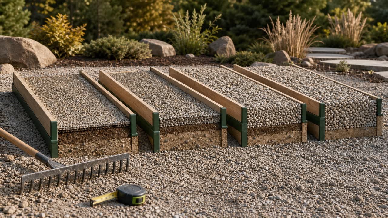
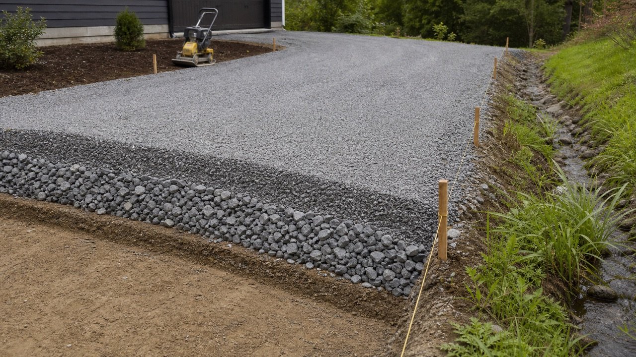
Excavation, stabilization, geotextile, base, surface, shoulder, and restoration often stop at different lines. Calculate each item from its approved footprint instead of applying one net area to the whole section.
- Clearing can extend beyond excavation for safe access or vegetation work.
- Undercut follows accepted weak ground rather than the planned surface edge.
- Structural fill can extend into a side slope below the bay.
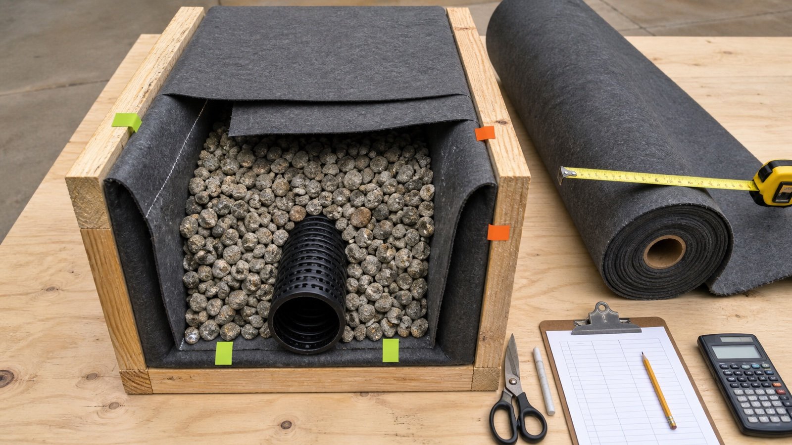
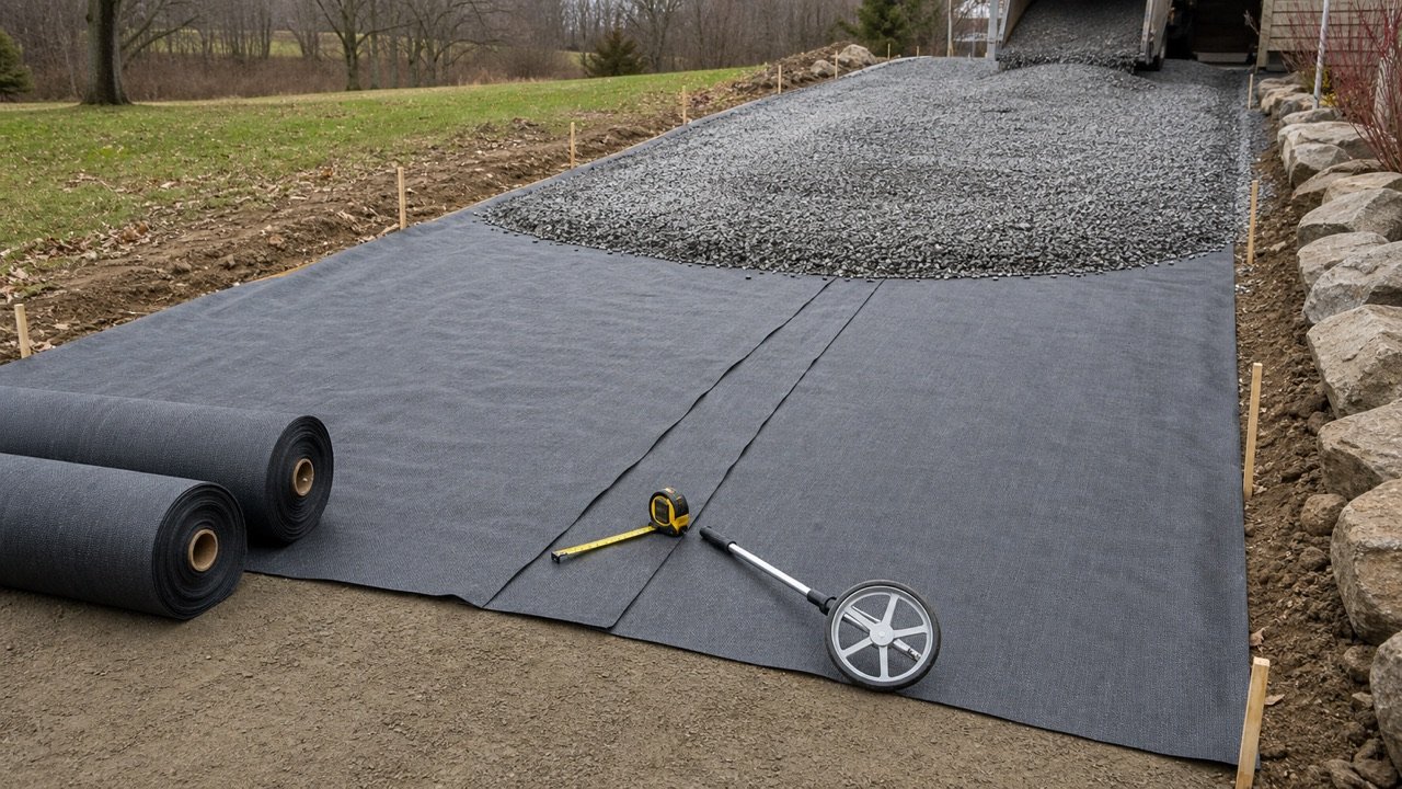
- Geotextile includes specified panels, overlaps, returns, penetrations, and roll cuts.
- Base may extend farther than visible surface gravel for edge support.
- A drain, paved channel, retained culvert, or island can interrupt selected layers.
- Shoulder and restoration use their own width, thickness, or cross-section.
Use the gravel driveway layer guide for selected compacted depths and the geotextile roll guide for panel planning.
Worked imperial passing-bay example
An approved hypothetical bay adds 8 ft beside a retained driveway for a 40 ft parallel section. Both straight tapers are 25 ft long. The new widening receives an 8 in compacted base and a 2 in compacted surface.
| Quantity | Calculation | Result |
|---|---|---|
| Parallel bay | 40 × 8 | 320 ft² |
| Entry and exit tapers | 2 × (25 × 8 ÷ 2) | 200 ft² |
| Net new footprint | 320 + 200 | 520 ft² |
| Compacted base | 520 × 8 ÷ 324 | 12.839506 yd³ |
| Compacted surface | 520 × 2 ÷ 324 | 3.209877 yd³ |
| Total compacted geometry | 12.839506 + 3.209877 | 16.049383 yd³ |
The dimensions verify arithmetic for a stated approved layout. They are not a fire-access or private-road recommendation. The 2 materials remain separate through supplier conversion.
Worked metric passing-bay example
A second approved hypothetical bay adds 2.8 m for a 12 m parallel section. Each straight taper is 6 m long. The widening receives a 180 mm compacted base and a 50 mm compacted surface.
| Quantity | Calculation | Result |
|---|---|---|
| Parallel bay | 12 × 2.8 | 33.600000 m² |
| Entry and exit tapers | 2 × (6 × 2.8 ÷ 2) | 16.800000 m² |
| Net new footprint | 33.6 + 16.8 | 50.400000 m² |
| Compacted base | 50.4 × 180 ÷ 1,000 | 9.072000 m³ |
| Compacted surface | 50.4 × 50 ÷ 1,000 | 2.520000 m³ |
| Total compacted geometry | 9.072 + 2.52 | 11.592000 m³ |
The measured area covers only the new widening. Any approved reconstruction inside the existing lane needs a separate layer line.
How is the outside edge length calculated?
Use the Pythagorean relationship for each straight taper edge, then add the parallel outside edge. This length can check an approved edging, shoulder, erosion-control, or restoration line.
Straight taper edge = √(taper length² + added width²)
In the imperial fixture, each taper edge is √(25² + 8²), or 26.248809 ft. Both taper edges plus the 40 ft outer edge total 92.497619 ft.
The metric fixture has 2 taper edges of √(6² + 2.8²). Adding the 12 m parallel edge gives 25.242356 m.
Use the line specified in the detail. An outer base edge, surface edge, edging centerline, fabric return, and restoration boundary can have different lengths.
How do grade and crossfall affect the takeoff?
A uniform layer volume does not include variable excavation or grading fill. Survey the existing surface and approved formation at taper endpoints, full-width corners, grade breaks, low points, and the retained-drive joint.
Split irregular ground into checked triangles or cross-sections. Multiply each triangular plan area by the average cut or fill depth at its 3 vertices when depth changes linearly inside the triangle.
Triangular cell volume = plan area × (d1 + d2 + d3) ÷ 3
Keep cut and fill separate. Excavated material can offset imported fill only after its type, condition, processing, specification, placement state, and acceptance are documented.
A bay built partly on a side slope can need a wider formation, benching, side slopes, drainage, erosion control, or retaining work. Those controls need approved cross-sections and can extend beyond the traffic surface.
How are sight distance and drainage treated?
Keep visibility and drainage areas outside the gravel-volume shortcut. They can change the approved location and disturbance area without becoming part of the structural bay surface.
| Control | Quantity effect | Evidence needed |
|---|---|---|
| Sight area | Vegetation clearing, earthwork, or relocation of the bay | Approved visibility assessment and maintenance limits |
| Crossfall and longitudinal grade | Variable cut, fill, pavement, and transition quantities | Surveyed levels and approved profile |
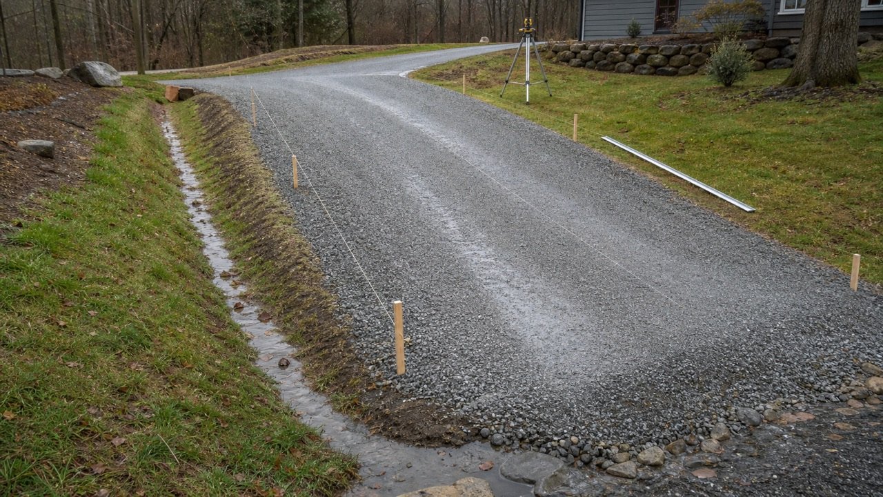
| Swale or ditch | Separate excavation, lining, culvert, outlet, and restoration | Drainage plan and stable discharge point |
| Permeable pavement system | Storage stone, filter layers, underdrain, and overflow | Approved stormwater and pavement design |
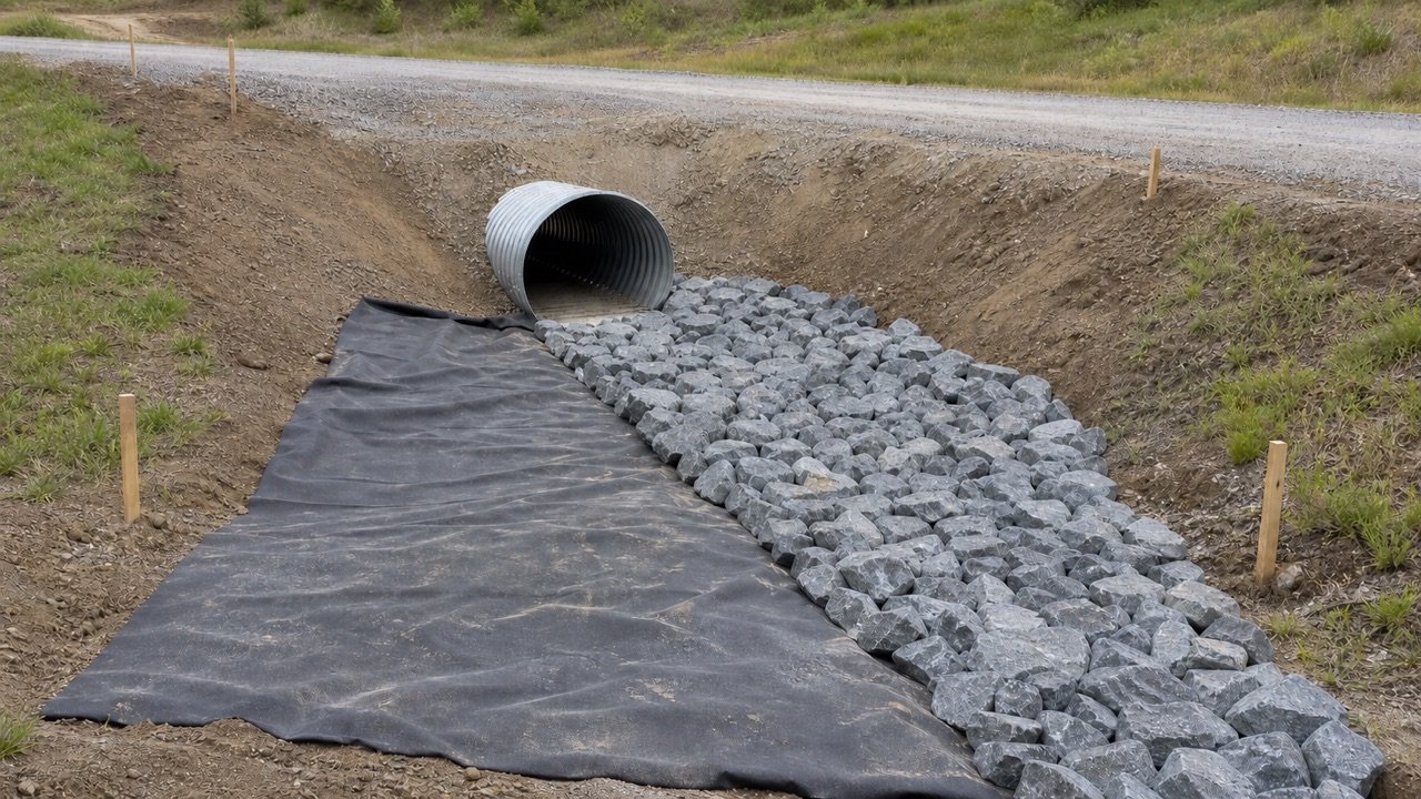
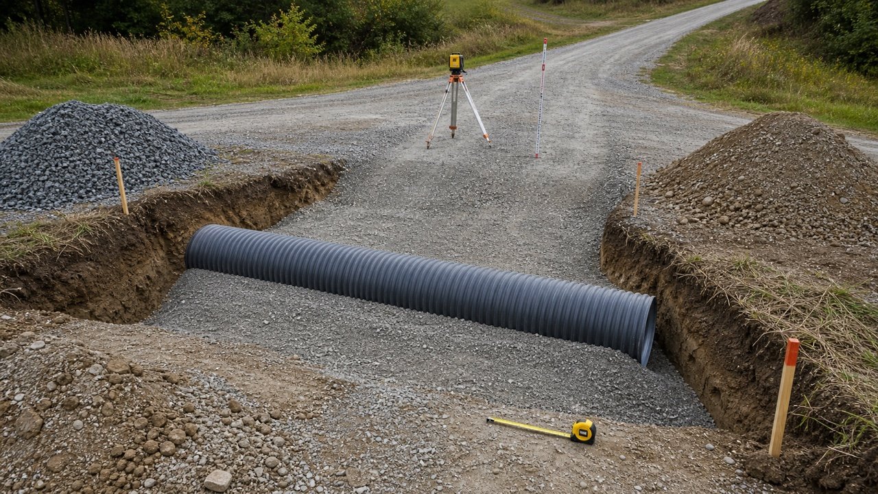
| Culvert crossing | Pipe, bedding, backfill, end treatment, and widening section | Hydraulic and structural detail |
| Utility or tree clearance | Footprint, excavation, protection, and restoration change | Verified location and responsible approval |
Highland Council's current private-access summary lists visibility, service bays, turning, drainage, permits, utilities, and construction as connected access issues. U.S. EPA stormwater guidance treats swales and permeable surfaces as designed systems.
Check the bay and route with the gravel driveway drainage guide. Surface gravel alone does not prove that runoff will infiltrate or reach a stable outlet.
Which conditions stop a quantity-only decision?
Pause the order when the approved location, vehicle operation, ground, drainage, or access conditions are unresolved. A larger gravel allowance cannot correct missing sight distance or an unsupported edge.
- The intended vehicles cannot pass within the checked clear envelope.
- A curve, crest, vegetation, or structure blocks the required view.
- The bay conflicts with a gate, bridge, culvert, hydrant, utility, well, septic asset, easement, or boundary.
- The widening places fill on an unstable slope or needs retaining support.
- Soft, wet, organic, pumping, or contaminated ground changes the section.
- Runoff would enter the driveway, public road, building, neighboring land, or an unstable outlet.
- Emergency access requires a verified load, clearance, grade, width, surface, interval, or maintenance plan.
- Construction traffic needs a turnout or control system under applicable workplace rules.
California Title 8 Section 1590 provides one workplace example: single-lane private construction roads with 2-way traffic require turnouts, or a control system where turnouts are impracticable. Its traffic, maintenance, and worker provisions belong to that jurisdiction and work scope.
How is the compacted volume converted into an order?
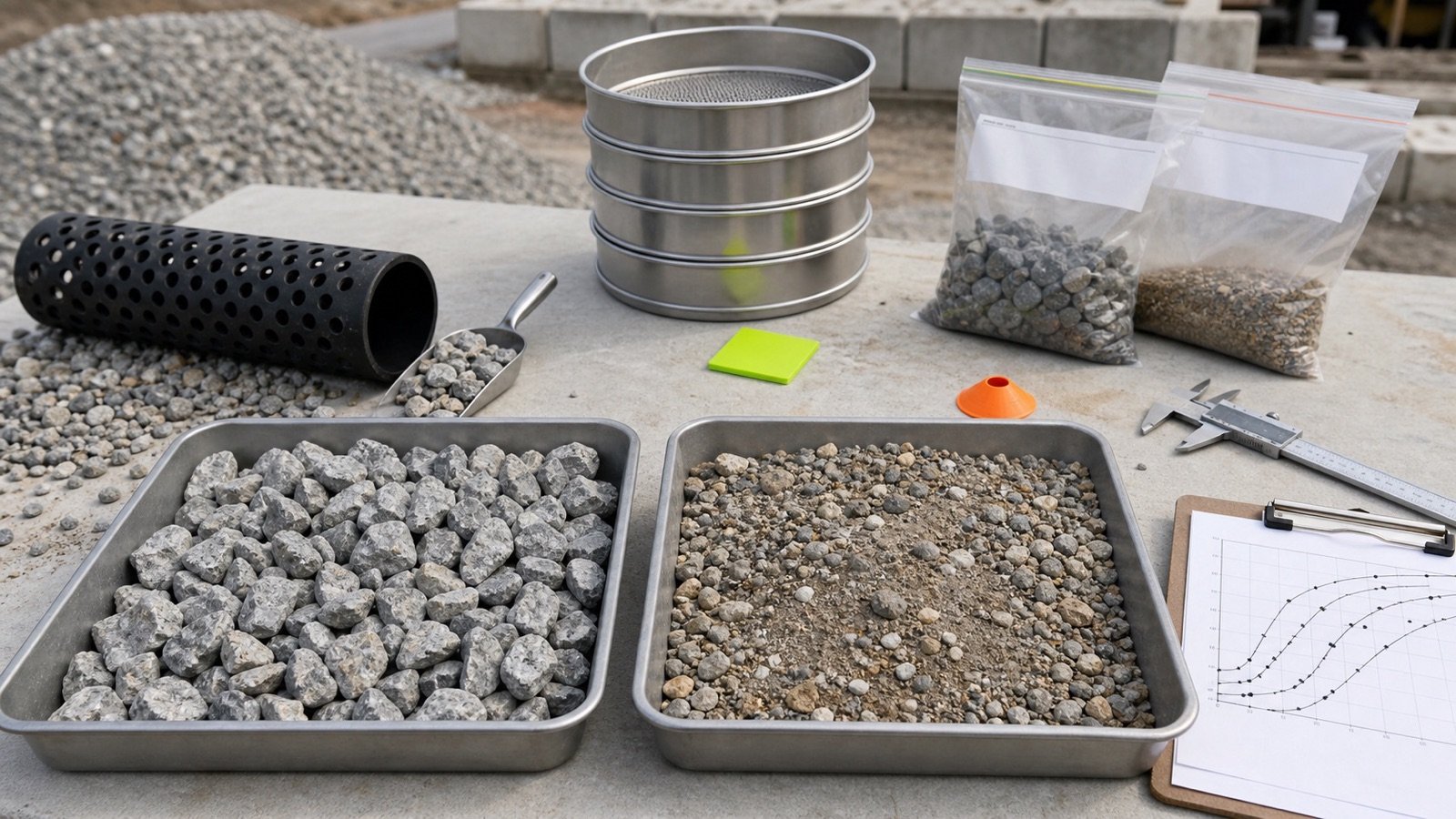
Convert each accepted layer using the selected product's evidence and the state in which the supplier sells it. Keep compacted geometry separate from loose delivery volume, mass, handling loss, and selling-unit rounding.
- Add all approved unrounded zones for one product.
- Deduct accepted reusable material in a compatible state.
- Apply a documented loose-to-compacted relationship when the quote uses loose volume.
- Use a product-specific bulk density in the matching state when the quote uses mass.
- Add a handling allowance only when project evidence supports it, and show it separately.
- Round once to the supplier's selling increment.
- Confirm minimum order, legal payload, access, unloading position, delivery fees, and quote expiry.
The gravel compaction guide explains the state conversion. Use the gravel cost guide to document the current supplier quote.
Common passing-bay quantity mistakes
- Using a turnout dimension from an unrelated authority or project.
- Calling a terminal turnaround or parking pad a passing bay.
- Multiplying added width by the full bounding length and filling both taper corners.
- Using the sloping outside edge as the triangle's taper length.
- Assuming both tapers have the same approved length.
- Counting the retained driveway again inside the widening.
- Omitting reconstructed driveway layers from the work.
- Using the visible loose-gravel edge as the accepted structural joint.
- Applying one footprint to clearing, cut, fill, fabric, base, surface, shoulder, and drainage.
- Using the deepest cut or fill across the whole bay.
- Treating vegetation clearing for sight distance as structural gravel area.
- Removing a ditch from the takeoff without measuring its replacement route.
- Using one density, compaction factor, waste percentage, or payload for every material.
- Rounding each triangle and layer before the product total is complete.
- Ordering before the bay location, formation, sight area, drainage, and traffic use are accepted.
What should the passing-bay record contain?
- Project, route, location, intended vehicles, date, weather, and existing condition.
- Authority, permit, access plan, pavement design, grading, drainage, survey, and revisions.
- Retained-drive edge, full-width bay points, taper points, widths, lengths, curves, and exclusions.
- Gross-area check, net widening area, overlap decisions, and independent verification.
- Existing and target levels, survey datum, crossfall, cut, fill, side slopes, and grade breaks.
- Separate excavation, stabilization, geotextile, base, surface, shoulder, drainage, and restoration limits.
- Outer-edge length and the exact measurement line for each linear item.
- Product, specification, material state, compacted depth, unrounded volume, and conversion evidence.
- Supplier, selling unit, increment, minimum order, payload, delivery route, fees, and quote date.
- Sight, traffic, emergency-access, utility, boundary, inspection, approval, and maintenance decisions.
- Prepared by, checked by, field changes, open items, and photographs.
Safety and scope
Control live and construction traffic, provide the required signs or spotters, locate overhead and buried utilities, protect open excavation and unstable edges, and keep workers clear of dumping and compaction. OSHA excavation guidance describes cave-in and related hazards for US workplaces.
This page checks quantity geometry and supplier records. It does not approve the passing operation, design vehicle, sight distance, emergency access, pavement loading, subgrade, slope support, drainage capacity, utilities, permits, traffic control, or construction.
Sources and source scope
- San Juan County, Fire Apparatus Access Site & Building Access Checklist: one current county example of driveway length, turnout, surface, grade, clearance, bridge, and turning controls.
- San Miguel Fire & Rescue, Building / Construction FAQs: current 2026 fire-access context that distinguishes turnouts from a terminal turnaround.
- Mono County, Chapter 22 Fire Safe Regulation: one local code example covering turnout geometry, driveway intervals, loading, grade, gates, and bridges.
- Highland Council, Private Access Guidance: current service-bay, turning, visibility, drainage, permit, utility, and construction context.
- California Department of Industrial Relations, Title 8 Section 1590: workplace turnout, traffic-control, maintenance, and worker-safety context for haulage and earthmoving.
- U.S. EPA, Stormwater Management Practices at EPA Facilities: designed swale, permeable pavement, and runoff-management context.
- NIST Guide to the SI, Appendix B.8: unit relationships used in the examples.
- OSHA, Trenching and Excavation: US workplace excavation-hazard scope.
Source scope: the authority sources show that turnout triggers and requirements vary. They do not supply one universal passing-bay size, gravel depth, product, density, allowance, crossfall, sight distance, or pavement section. The worked examples verify geometry for stated hypothetical approved layouts.
Run each compatible rectangle or uniform taper through the Driveway Gravel Calculator and sum the unrounded section results by product. Use the Gravel Calculator for one verified material footprint, measure a road connection with the driveway apron guide, or return to the Gravel planning hub.