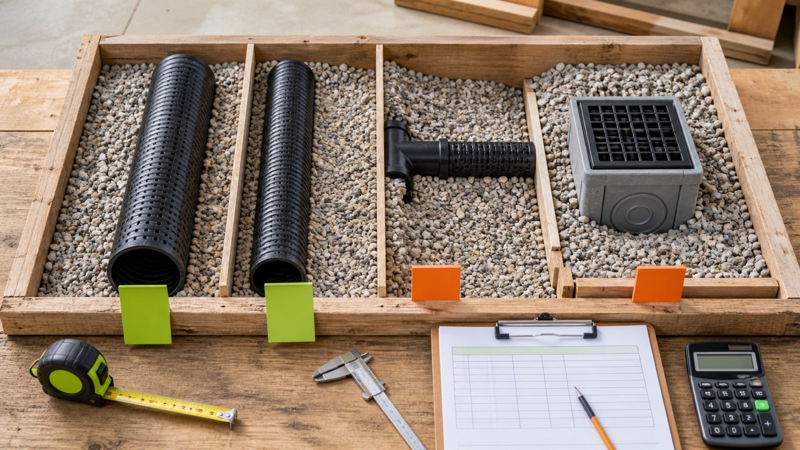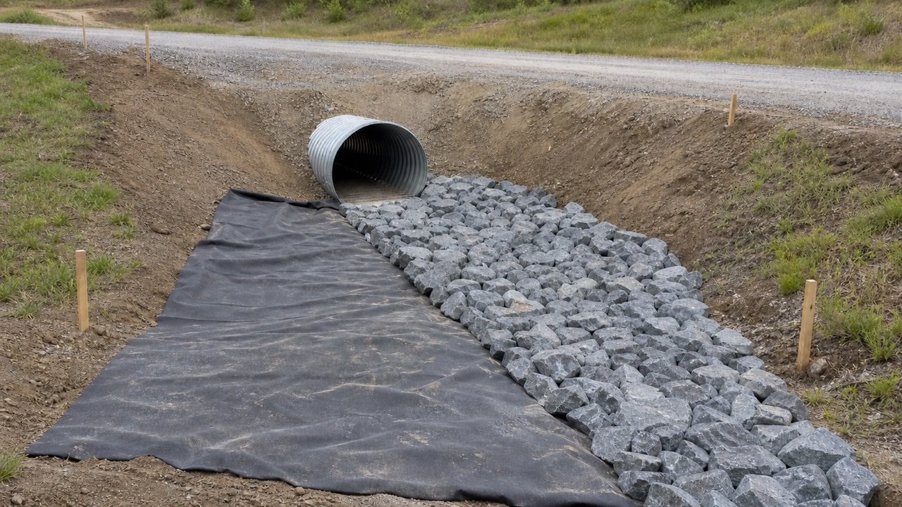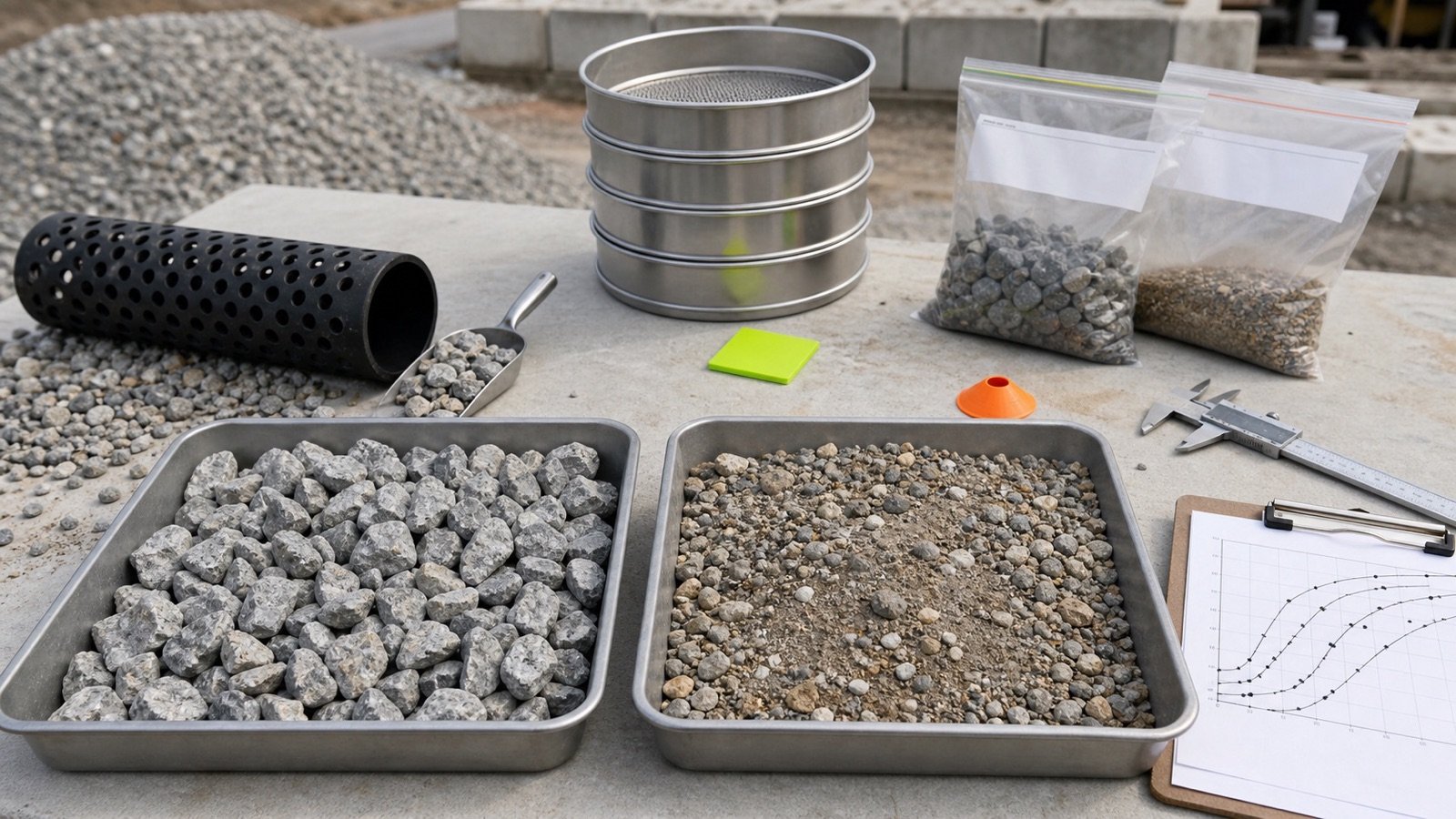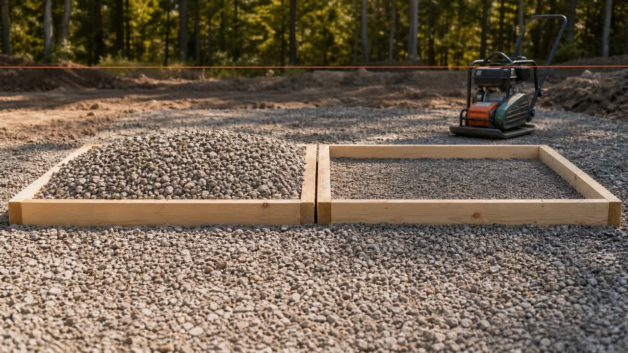
A drainage-trench fabric takeoff starts with the approved cross-section. Trace the exact path of the geotextile around the gravel, then add each required closure, end seam, junction piece and repair patch.
Keep developed coverage, fabric cut from the roll and nominal purchased roll area as separate quantities. They answer different questions.
How do you calculate geotextile for a drainage trench?
Calculate the developed fabric width across the trench section. Multiply it by the seam-adjusted cut length, then compare that layout with the confirmed roll width and length.
Use the Drainage Gravel Calculator for the gravel zone. Use the same section limits here so the fabric and gravel records describe one approved detail.
A project may specify a full wrap, U-shaped liner, partial wrap, separate cap or no fabric at one interface. Do not assume that every drain uses a closed rectangular wrap.
Which inputs belong in the fabric ledger?
| Input | Source | Check |
|---|---|---|
| Section ID and route length | Plan and measurement sheet | Clear start and end limits |
| Fabric path | Approved cross-section | Bottom, sides, top returns and exclusions |
| Closure overlap | Detail, specification or accepted instructions | Location and direction |
| End or transverse overlap | Detail, specification or accepted instructions | Number of seams |
| Roll width and length | Exact product record or quote | Usable dimensions and units |
| Seam method | Approved installation requirement | Overlap, sewing or another accepted joint |
| Patches and penetrations | Detail and field record | Each piece and extension |
| Product identity | Accepted submittal | Roll label, lot and specification |
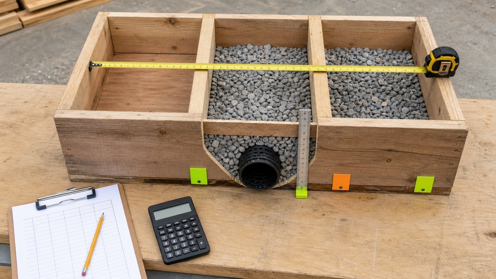
The drainage-trench measurement guide shows how to keep widths, depths and section limits paired.
What fabric path does the detail show?
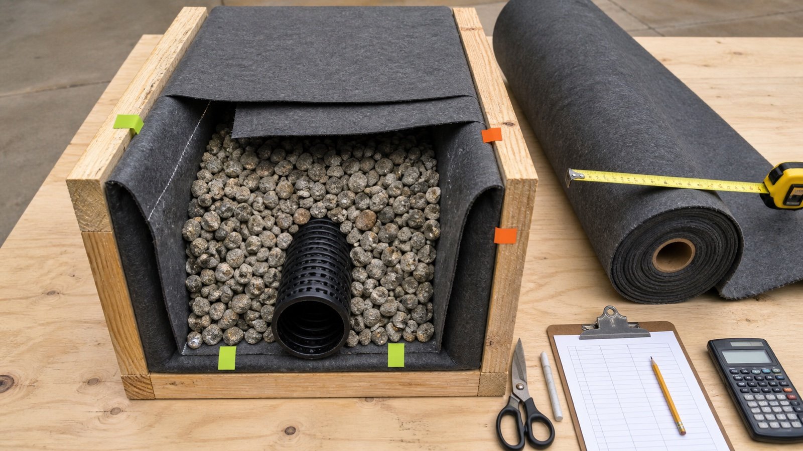
Mark every covered face on a copy of the cross-section. A full rectangular wrap includes the bottom, both sides, the top width and the approved closure overlap. A U-shaped liner stops before the top closure. A partial wrap follows only the faces shown.
| Boundary | Developed width record |
|---|---|
| Full rectangular wrap | Bottom + 2 sides + top + closure overlap |
| U-shaped liner | Bottom + 2 sides + specified returns |
| Bottom and one side | Only the shown faces and termination allowance |
| Separate top cap | Cap width and seams on another cut line |
| Structure or junction | Dedicated piece or patch schedule |
FHWA pavement guidance includes layouts where geotextile wraps only part of an edge-drain trench and stays away from one permeable-base interface. That highway example confirms that the drawing controls the path; it does not define a residential French-drain wrap.
How is full-wrap developed width calculated?
For a closed rectangular wrap made from one sheet across the trench, add the bottom, both sides, top width and closure overlap.
Developed wrap width = 2 x gravel-zone width + 2 x wrapped height + closure overlap
The second gravel-zone width represents the top closure across the trench. Use the actual fabric path when the top is open, the sides stop at different levels or the section is shaped.
How do end seams change the cut length?
Each installed end seam consumes the approved overlap length. Count the pieces first, then add one end overlap for every joint between pieces.
Installed pieces = 1 when route length is at or below roll length
Additional pieces = ceiling((route length - roll length) / (roll length - end overlap))
Required cut length = route length + (installed pieces - 1) x end overlap
The formula assumes each piece can use the full roll length and every end seam uses the same approved overlap. Curves, staggered joints, sewn seams or restricted seam locations need a cut schedule.
Worked metric example: 40 m full-wrap trench
An approved full wrap covers a 40 m route. The gravel zone is 0.5 m wide and 0.6 m high. The detail gives 0.3 m closure overlap and 0.5 m end overlap. The confirmed roll is 3 m wide and 25 m long.
- Developed width: 2 x 0.5 + 2 x 0.6 + 0.3 = 2.5 m.
- One 25 m piece does not cover 40 m, so the layout needs 2 pieces.
- Required cut length: 40 + 0.5 = 40.5 m.
- Developed coverage basis: 2.5 x 40.5 = 101.25 m2.
- Full-width fabric removed from the 3 m roll: 3 x 40.5 = 121.5 m2.
- Whole-roll purchase: ceiling(40.5 / 25) = 2 rolls.
- Nominal purchased area: 2 x 3 x 25 = 150 m2.
The 48.75 m2 difference between developed coverage and nominal purchased area includes width trimming and unused roll length. Treat an offcut as reusable only after the cut plan assigns it to an approved piece.
Why can nominal roll area overstate usable coverage?
Nominal area equals roll width times roll length. A trench wrap may use the full roll width while its developed width is smaller, leaving a long side strip. End seams also consume length.
| Quantity | Metric example | Use |
|---|---|---|
| Developed coverage basis | 101.25 m2 | Approved wrap path plus end seam |
| Full-width fabric cut | 121.5 m2 | Material removed from 3 m roll width |
| Nominal purchase | 150 m2 | Two complete rolls |
| Unassigned remainder | 48.75 m2 by area balance | Width strips and unused length requiring a cut record |
Area balance alone does not prove that scraps have the right width, length, seam direction or condition for another location.
What happens when the roll is narrower than the wrap?
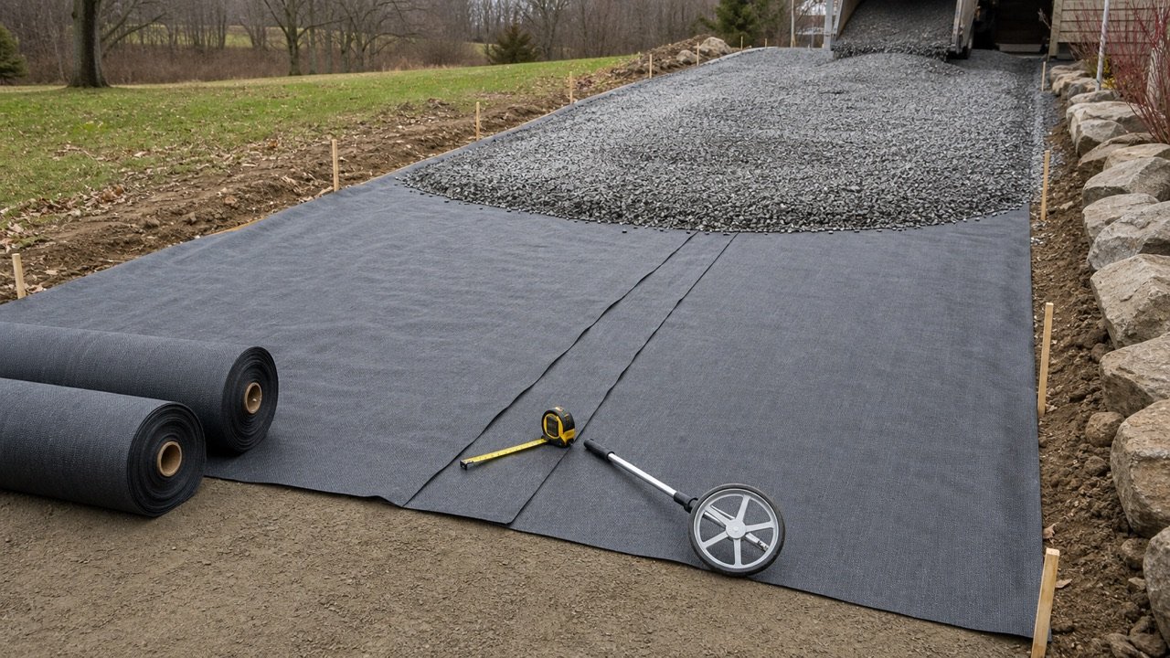
A one-piece cross-trench wrap needs a roll at least as wide as the developed width. A narrower roll requires longitudinal lanes, approved seams and a layout that shows where those seams may sit.
Do not divide developed width by roll width and add a generic percentage. Record every lane width, longitudinal overlap, end overlap and termination. Fabric direction and seam strength may also matter under the accepted specification.
Worked imperial example: one wide roll
An 80 ft route has an approved full-wrap section 18 in wide and 24 in high. The closure overlap is 12 in. No end seam is needed. The confirmed roll measures 8.5 ft x 100 ft.
- Developed width: 2 x 1.5 + 2 x 2 + 1 = 8 ft.
- Required cut length: 80 ft.
- Developed coverage basis: 8 x 80 = 640 ft2.
- Full-width fabric removed: 8.5 x 80 = 680 ft2.
- Purchase: 1 roll with 850 ft2 nominal area.
The remaining 20 ft of full roll length and the 0.5 ft width strip need separate dimensions in the remnant record.
How should branches and junctions be measured?
Stop main and lateral sheets at the approved junction boundaries. Give the junction its own fabric piece, overlap and penetration record.
The multiple-pipe and structure guide uses the same straight-run and junction boundaries for gravel. Matching IDs prevent a lateral from being counted through the main and again in a junction patch.
| Piece | Quantity basis |
|---|---|
| Main wrap | Clear run plus approved end seam |
| Lateral wrap | Clear branch length plus approved end seam |
| Junction piece | Detail dimensions, penetrations and overlaps |
| Closure strip | Separate width and seam schedule when shown |
How are basins, chambers and penetrations recorded?
Use dedicated pieces for a basin, chamber or pipe penetration when the detail shows them. Record cut shape, opening, return, lap and patch dimensions from the approved layout.
A rectangle based on structure footprint alone misses vertical faces, returns and pipe openings. A full pocket wrap may also create corner folds that use fabric without adding flat covered area.
How should damage patches affect the order?
Record damage after inspection and use the repair dimensions required by the applicable specification or accepted instructions. Add each approved patch as a cut piece with its own seam extension.
An FHWA SPS-2 example used one overlap for its joints and another extension for damage patches. Those values belong to that test-pavement specification. They show why the takeoff needs separate seam and repair fields.
How should a roll-cut plan be checked?
Assign every required piece to a roll before counting remnants as available. Record roll number, piece ID, cut width, cut length, orientation and remaining dimensions.
- Fit long continuous pieces first when the approved seam layout permits it.
- Keep branch and patch pieces beside their section IDs.
- Do not combine 2 narrow scraps into one wide piece without an approved seam.
- Quarantine torn, contaminated or unidentified remnants.
- Recalculate after a width, depth, overlap or roll-size change.
Which geotextile quantity mistakes cause shortages?
- Measuring only trench bottom area.
- Assuming a full wrap when the detail shows another boundary.
- Using one percentage instead of counting closure and end seams.
- Treating nominal roll area as installed coverage.
- Ignoring roll width and checking only total square area.
- Omitting branch, junction, structure and penetration pieces.
- Counting the same junction length in main and lateral sheets.
- Reusing an offcut without checking its dimensions and orientation.
- Applying one project's overlap or patch size to another project.
- Entering an excavation without required authorization and controls.
What selection, installation and safety limits apply?
This guide calculates quantity from an approved layout. It does not select woven or nonwoven fabric, filtration properties, apparent opening size, permeability, strength, survivability class, seam type, anchors, exposure period or repair method.
FHWA examples tie geotextile properties and placement to soil, aggregate, installation stress, drawings and specifications. NRCS directs users from its national standard to local technical guidance. Use the accepted product, project detail and responsible designer.
OSHA requires covered U.S. excavation work to address utilities, cave-ins, water, access, protective systems and competent-person inspections. Other jurisdictions may use different or stricter controls.
The Gravel Planning hub lists drainage, measurement and supplier-order resources.
Sources and source scope
- FHWA-HRT-01-167, Appendix A: project-specific edge-drain filter fabric, joint, placement and repair requirements.
- FHWA NHI-05-037, Chapter 7: partial trench-wrap and interface-specific geotextile context.
- NRCS Subsurface Drain (Ft.) (606): national record and local-guidance boundary.
- OSHA Trenching and Excavation eTool: U.S. excavation hazard planning and inspection context.
- NIST Handbook 44 (2026), Appendix C: exact U.S. customary and SI length relationships.
Source scope: FHWA examples support drawing- and specification-controlled layout, properties, seams and repairs. NRCS supports the local-guidance boundary, OSHA supports the stated U.S. workplace hazards, and NIST supports conversions. The project detail and accepted product control the actual fabric path and overlap.
Review note: Saleem Sial owns the research and editorial record. Source checks, independent fixtures, editorial review, build validation, link crawl, schema review and rendered QA form the internal publication gate. Waseem Sial, External Reviewer and Engineer, is listed for ongoing external review; no completed review date is claimed.