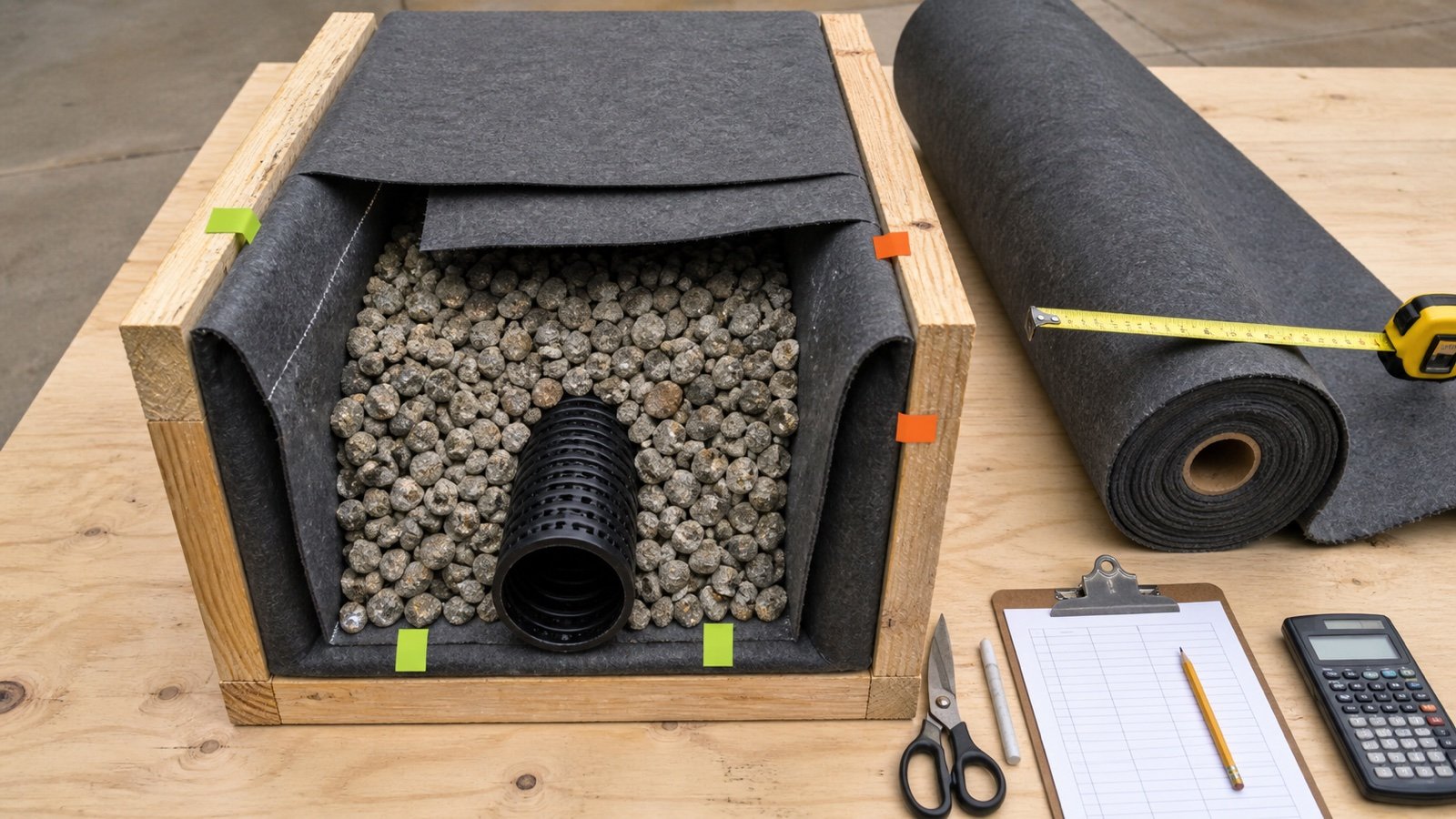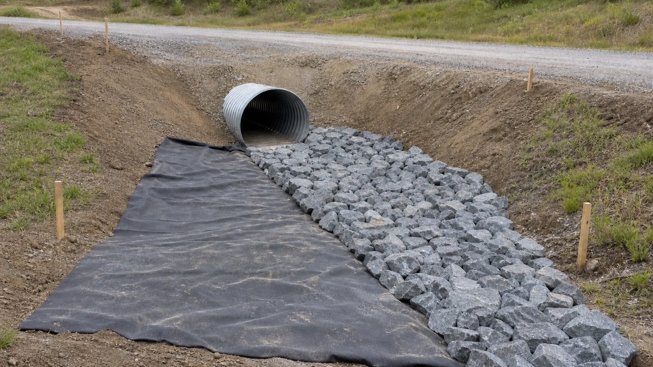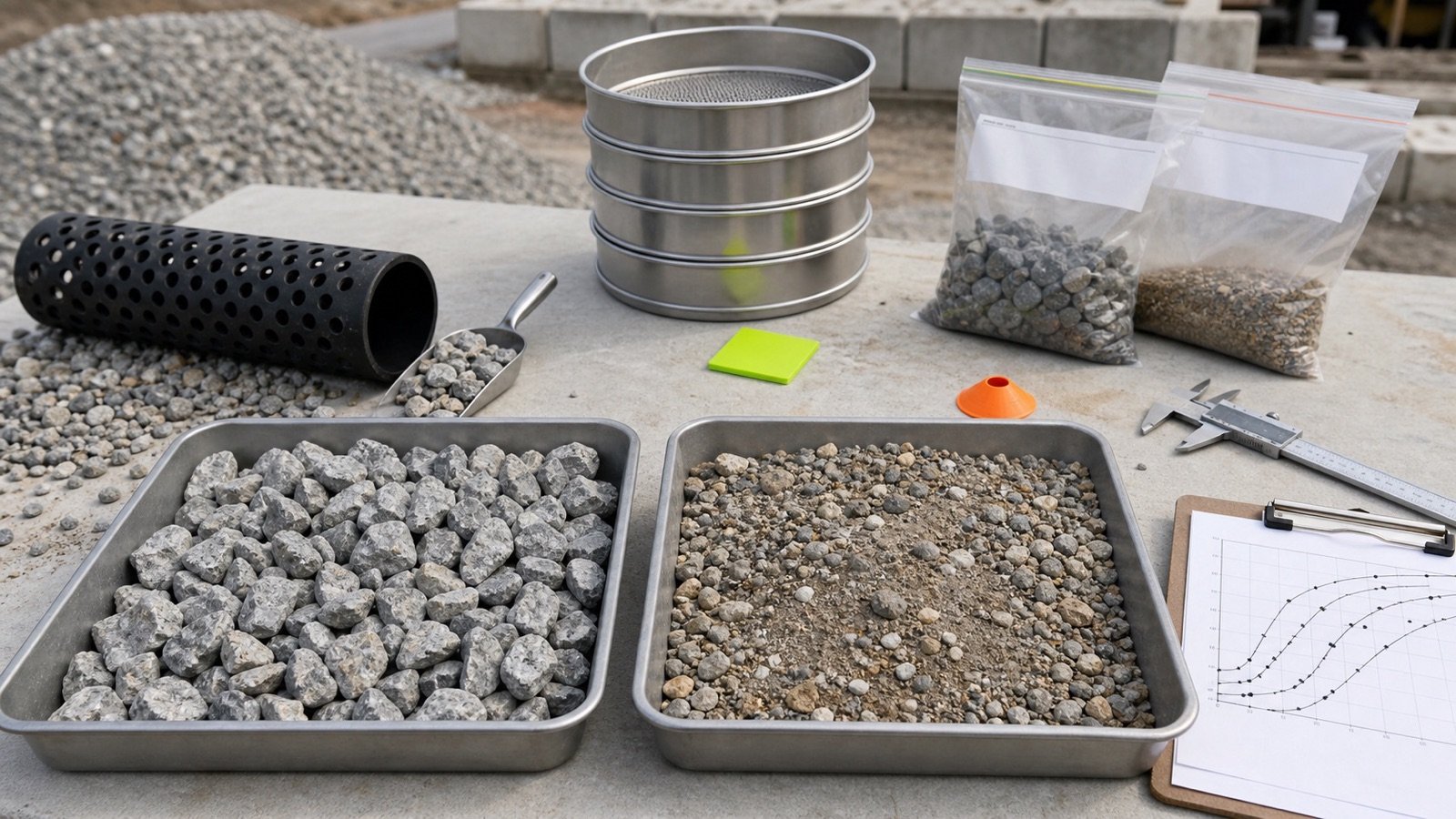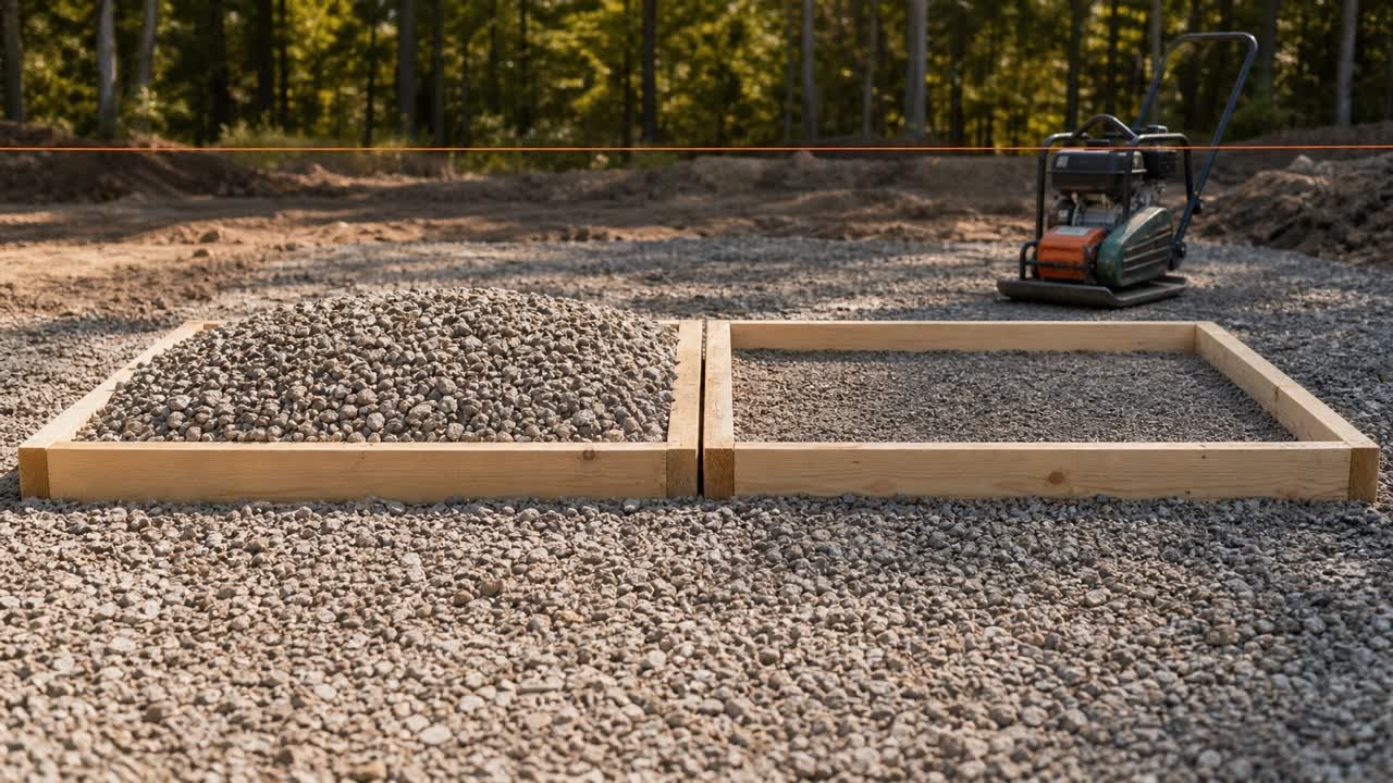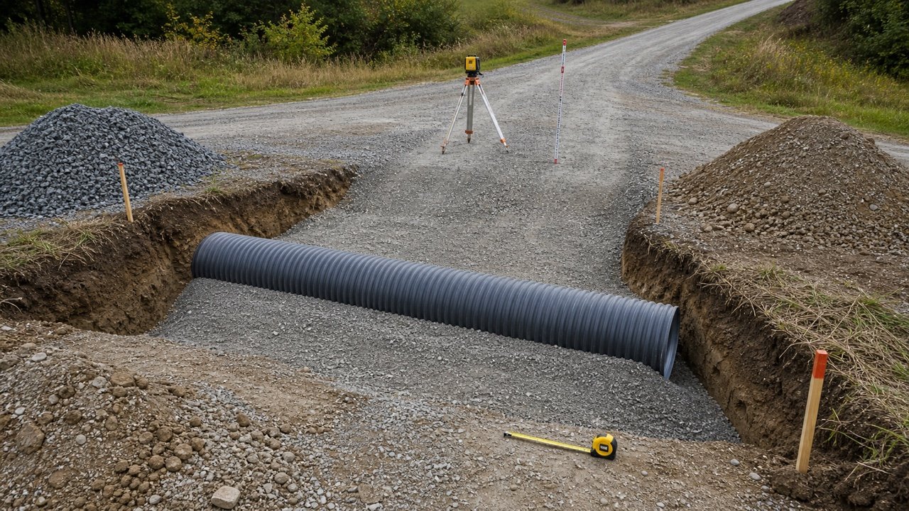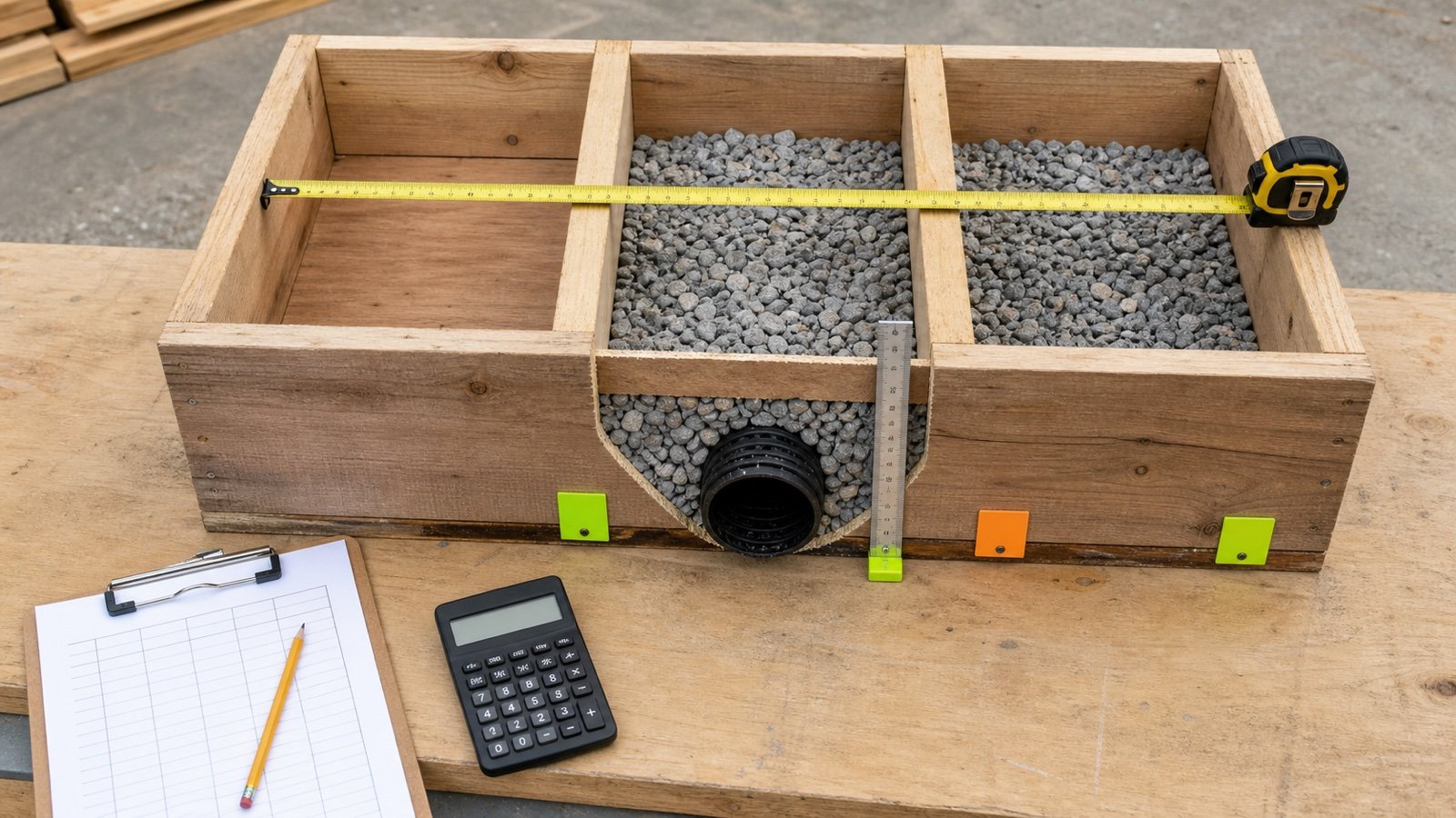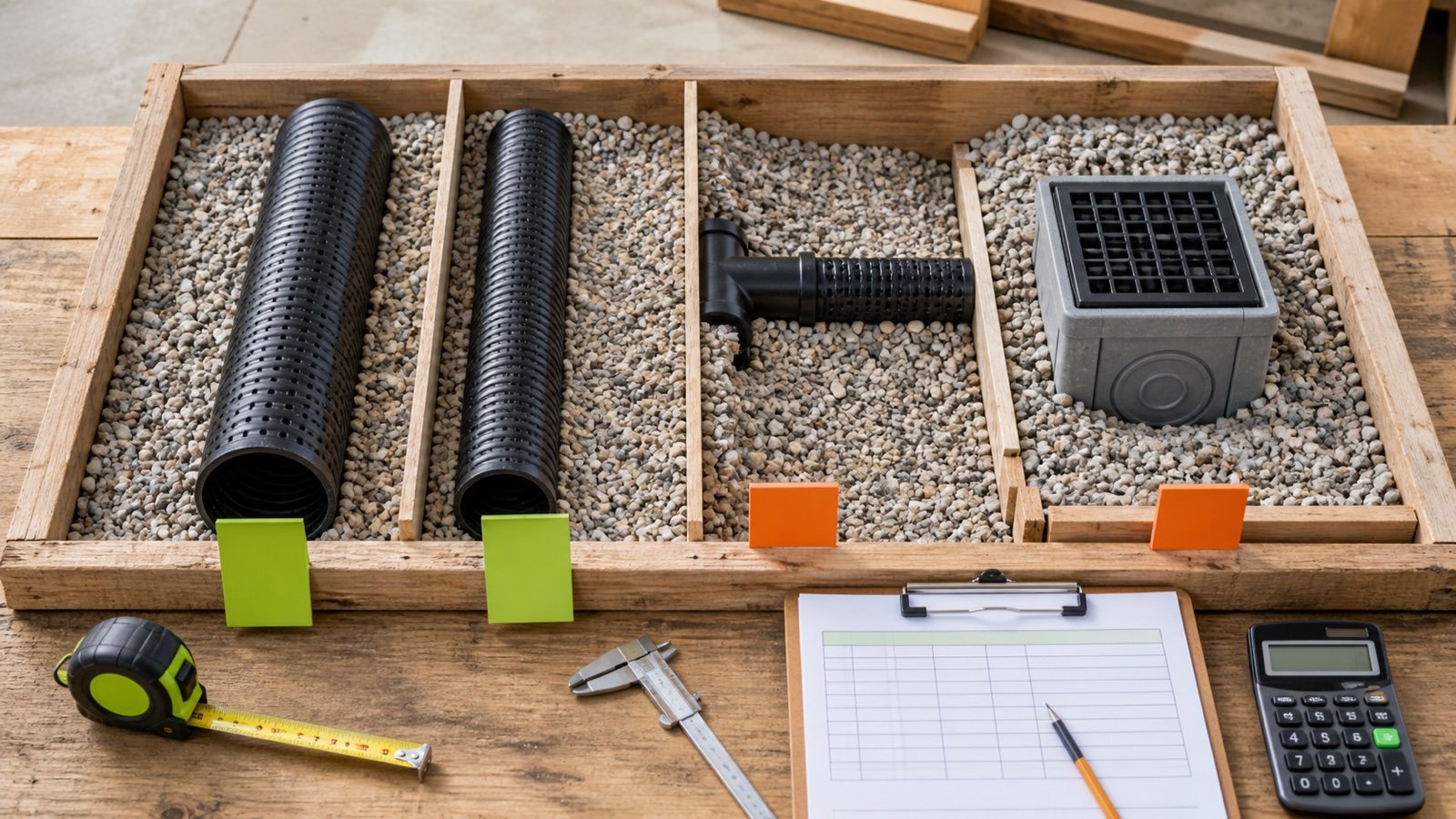
A drainage route with 2 pipes, a branch or a catch basin needs more than one cylinder deduction. Divide the work into straight runs, junctions and structure pockets before calculating gravel.
Each physical space belongs to one quantity section. Each pipe, fitting or structure receives one displacement line inside that section.
How do you calculate gravel around multiple drainage components?
Calculate the gross gravel zone for each section. Subtract the outside volume of every pipe length, fitting and structure that occupies that section, then add the unrounded net gravel volumes.
Use the Drainage Gravel Calculator for one constant rectangular zone with one full-length pipe. Use a separate worksheet for unequal pipe lengths, multiple diameters, junctions or structures.
Stop a straight pipe at the exterior face of a fitting, basin or chamber. Deduct the component once so pipe and structure volumes do not overlap.
Which fields belong in a component ledger?
| Field | Example | Reason |
|---|---|---|
| Section ID | R1, J1 or S1 | Separates straight run, junction and structure pocket |
| Start and end limit | Sta. 0+000 to basin outer face | Prevents length overlap |
| Gravel boundary | Width, depth and shape | Defines gross volume |
| Component ID | P1, tee T1 or basin CB1 | Links the deduction to the drawing and product |
| Exterior dimensions | Actual OD or approved outside box | Measures occupied space |
| Included length or height | Length inside this section | Limits the displacement |
| Source and revision | Plan, detail or accepted product data | Makes the entry reviewable |
| Net placed gravel | Unrounded section result | Supports product totals |
The drainage-trench measurement guide explains station limits and changing cross-sections. Keep the same section IDs in both records.
How are multiple straight pipes deducted?
Use each pipe's actual outside diameter and the length that sits inside the gravel zone. Add the pipe displacements, then subtract their total from the gross zone.
Pipe displacement i = pi x (actual OD i / 2)^2 x included length i
Net placed gravel = gross gravel zone - sum of component displacements
Equal pipes can share one line when their diameter, length, section limits and product record match. Use separate lines when a diameter or included length changes.
Worked example: 2 full-length parallel pipes
An approved rectangular gravel zone is 20 m long, 1.2 m wide and 0.6 m deep. Two parallel pipes each have a checked 315 mm actual outside diameter and occupy the full 20 m section.
- Gross gravel zone: 20 x 1.2 x 0.6 = 14.4000 m3.
- One pipe: pi x 0.1575^2 x 20 = 1.5586 m3.
- Two pipes: 2 x 1.5586 = 3.1172 m3.
- Net placed gravel: 14.4000 - 3.1172 = 11.2828 m3.
The arithmetic confirms volume for the entered geometry. It does not approve the 1.2 m width, pipe spacing, support, cover or arrangement.
Can a pipe count replace separate length records?
A common pipe count works only when every included pipe has the same OD and length inside the same gravel section. A short lateral or a pipe that starts at a basin needs its own length.
Consider a 24 m gravel zone that is 0.9 m wide and 0.5 m deep. Pipe A has 160 mm OD through 24 m. Pipe B has 110 mm OD through 10 m.
- Gross zone: 24 x 0.9 x 0.5 = 10.8000 m3.
- Pipe A: pi x 0.08^2 x 24 = 0.4825 m3.
- Pipe B: pi x 0.055^2 x 10 = 0.0950 m3.
- Net placed gravel: 10.8000 - 0.4825 - 0.0950 = 10.2224 m3.
Multiplying the 160 mm pipe displacement by 2 would apply the wrong diameter and length to Pipe B.
Does a geometric fit check approve pipe spacing?
A quantity worksheet can flag an impossible entry. It cannot select the clear spacing, side clearance, bedding class, pipe support or trench width.
For parallel pipes at a common level, the sum of outside diameters must be less than the inside gravel-zone width before any specified gaps or side clearances are added. Passing that basic check does not prove that the layout meets project requirements.
| Check | Quantity response |
|---|---|
| Combined ODs exceed zone width | Reject the section as physically inconsistent |
| Pipe top or bottom crosses gravel boundary | Revise the zone or use the approved partial geometry |
| Pipes sit at different levels | Record the approved section and component positions |
| Specified gaps are unknown | Hold the quantity as unresolved |
| One pipe leaves the section early | Split its included length or section |
Where should straight runs stop at a junction?
Stop each straight cylinder at the exterior boundary of the tee, wye, coupling or fabricated junction. Record the fitting as a separate component using accepted exterior geometry.
Running every pipe centerline through the junction and then deducting the fitting subtracts overlapping space twice. A plan length also may extend to a node center while the physical straight pipe ends at a socket or fitting face.
Use approved product data, shop information or measured accepted components for the fitting envelope. Leave the deduction unresolved when the exterior geometry is unavailable and the quantity effect matters.
How should a branch network be divided?
Assign one section to each constant main run and lateral. Stop lateral lengths at the main fitting boundary. Use a junction section for the tee, wye or collector detail.
| Section | Gross gravel space | Deductions |
|---|---|---|
| Main run R1 | Clear length to Junction J1 | Main pipe within R1 |
| Lateral R2 | Clear length to Junction J1 | Lateral pipe within R2 |
| Junction J1 | Approved junction gravel envelope | Fitting exterior and pipe stubs within J1 |
| Downstream run R3 | Clear length from Junction J1 | Downstream pipe within R3 |
Add clear lengths once. A node-to-node schedule and a physical cut-length schedule may use different endpoints, so label the length basis.
How is gravel around a catch basin calculated?
Calculate the gross gravel pocket shown by the approved detail. Subtract the catch basin's exterior volume inside that pocket and any pipe-stub volumes that stop at its outer faces.
Net structure-pocket gravel = gross pocket - structure exterior - included pipe stubs - other documented components
Use exterior basin dimensions. Internal storage volume does not describe the space displaced in the gravel pocket. A base, riser, frame, grate, sump, concrete surround or shaped foundation may change the exterior envelope.
Worked example: catch-basin gravel pocket
An approved gravel pocket measures 1.2 m x 1.2 m x 1.0 m. A rectangular catch-basin exterior inside the pocket measures 0.6 m x 0.6 m x 0.8 m. Three 110 mm OD pipe stubs each occupy 0.3 m inside the pocket and stop at the basin faces.
- Gross pocket: 1.2 x 1.2 x 1.0 = 1.4400 m3.
- Basin exterior: 0.6 x 0.6 x 0.8 = 0.2880 m3.
- Three pipe stubs: 3 x pi x 0.055^2 x 0.3 = 0.0086 m3.
- Net placed gravel: 1.4400 - 0.2880 - 0.0086 = 1.1434 m3.
The example uses a simple exterior box from an assumed approved detail. Use the selected structure's actual external shape and included height.
How can overlapping deductions be found?
Draw every deducted component inside its quantity section. Two deduction shapes should not occupy the same physical space unless you calculate their geometric union.
- Stop a straight pipe at the fitting or structure face.
- Stop a structure deduction at the gravel-zone boundary.
- Assign each pipe stub to one section.
- Keep concrete surround, bedding and drainage gravel in separate material zones.
- Flag any component volume that crosses another component or section limit.
A simple reconciliation is `gross zone = net gravel + all non-overlapping component displacement`. The section needs review when those parts do not return to the gross volume.
How are changing cross-sections handled?
Split the route where gravel width, depth, pipe count or component arrangement changes. Calculate each gross segment from paired station areas, then subtract only the pipe lengths inside that segment.
Do not extend a 2-pipe deduction through a downstream one-pipe section. The measurement guide shows the end-area method for varying widths and depths.
How should placed volume become an order quantity?
Add unrounded net placed gravel for sections that use the same product and material state. Apply a documented supplier-basis conversion and selling increment after the geometric takeoff.
The calculator accepts a user-entered state increase, supplier density and volume increment. Keep loose volume, placed volume, handling loss, contingency, density, truck payload and minimum delivery as separate records.
A current supplier quote or product record must identify the gravel, selling unit, volume or mass basis, increment, delivery terms and date. This guide provides no default density or allowance.
Which multiple-component mistakes change the result?
- Multiplying one pipe volume by a count when diameters or lengths differ.
- Extending a second pipe through a section where it is absent.
- Using nominal size in place of actual outside diameter.
- Running straight cylinders through a fitting and deducting the fitting again.
- Using a basin's internal storage volume as exterior displacement.
- Applying one rectangular pocket to a shaped or stepped structure.
- Combining pipe, concrete surround and gravel in one material quantity.
- Rounding each component before calculating the section total.
- Using a fit check as approval of spacing or support.
- Entering an excavation without the required safety process.
What design and excavation limits apply?
This method checks material geometry after the layout has been selected. It does not design pipe capacity, spacing, bedding, support, filter compatibility, structure capacity, grade, outlet or drainage performance.
NRCS directs users from its national standard to applicable local technical guidance. FHWA drainage guidance connects excavation, pipe bedding and minor structures to project details and site conditions. Use the governing drawings, accepted products and responsible project people.
OSHA requires covered U.S. excavation work to address utilities, cave-ins, water, access, protective systems and competent-person inspections. Other jurisdictions may use different or stricter controls.
Use the pipe outside-diameter guide to source displacement inputs. The Trench Excavation Calculator handles gross excavation, and the Gravel Planning hub lists related quantity records.
Sources and source scope
- NRCS Subsurface Drain (Ft.) (606): national practice-standard record and local-guidance boundary.
- FHWA Drainage Guidelines: excavation, pipe bedding and minor-structure review context.
- OSHA Trenching and Excavation eTool: U.S. excavation hazard planning and inspection context.
- NIST Handbook 44 (2026), Appendix C: exact inch, foot, yard and SI conversion relationships.
Source scope: NRCS and FHWA support the need for project and local technical details. OSHA supports the stated U.S. workplace hazards. NIST supports unit conversions. Project drawings and accepted component data supply the actual geometry.
Review note: Saleem Sial owns the research and editorial record. Source checks, independent fixtures, editorial review, build validation, link crawl, schema review and rendered QA form the internal publication gate. Waseem Sial, External Reviewer and Engineer, is listed for ongoing external review; no completed review date is claimed.