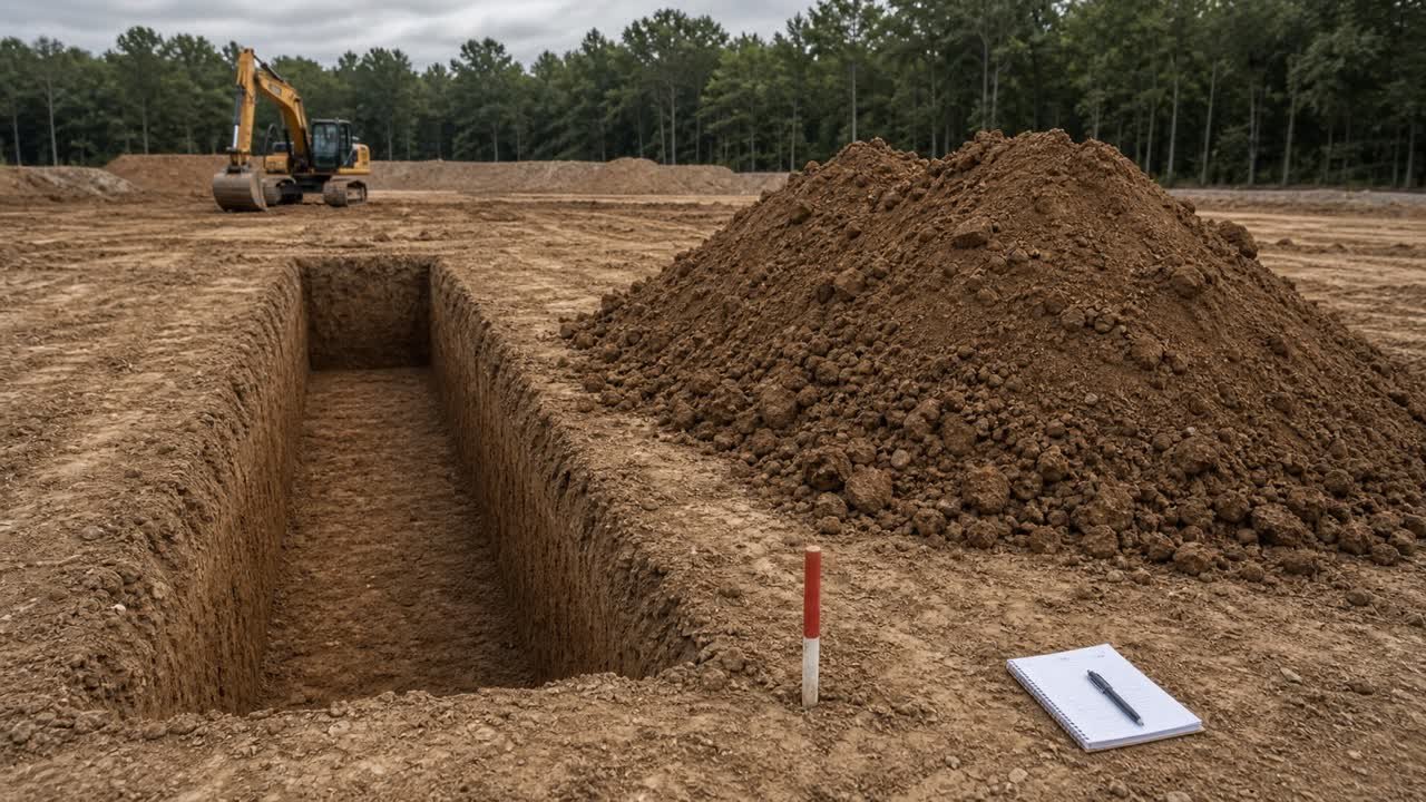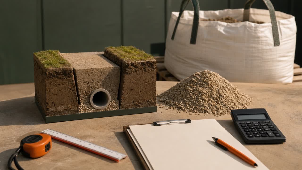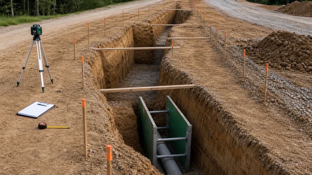
A buried-pipe trench can contain several material zones with different boundaries, materials, placement rules, and quantity states. The labels on the governing drawing tell you where one zone ends and the next begins.
Record those boundaries before calculating volume. Bedding, haunch, pipe zone, initial backfill, and final backfill do not have one universal set of depths or material requirements across every pipe system and jurisdiction.
Which zones make up pipe bedding and backfill?
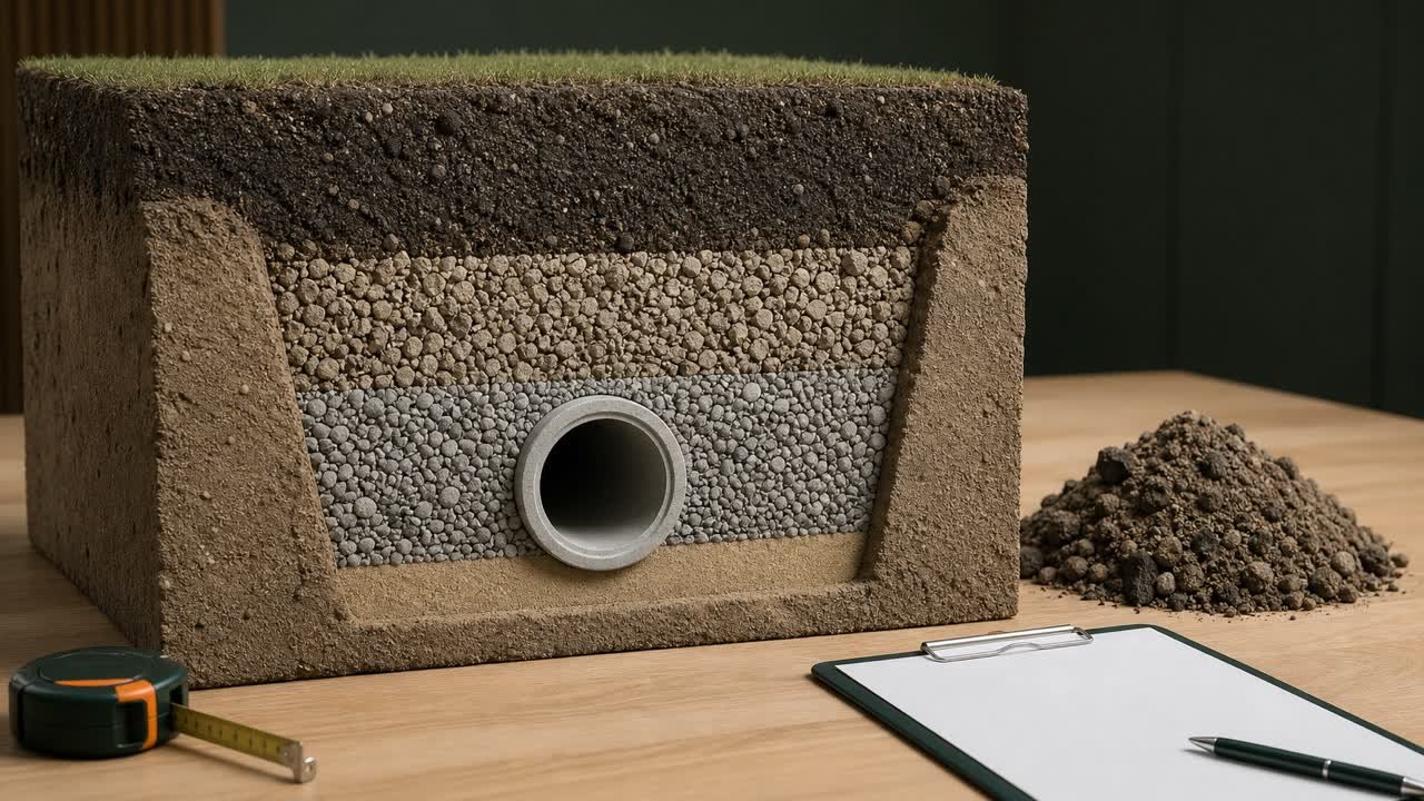
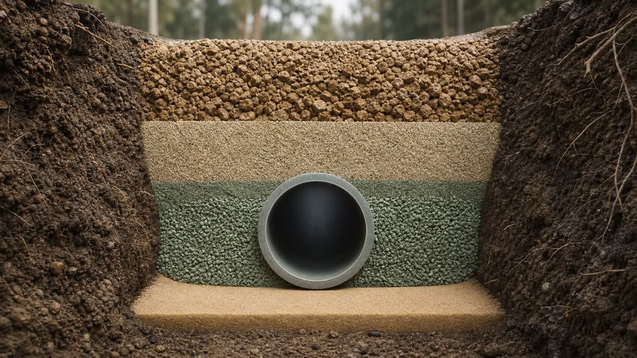
A typical detail may show foundation below the pipe, bedding under the barrel, haunch material beside the lower pipe quadrants, primary backfill up to the crown, secondary or initial backfill above the crown, and final backfill up to the stated surface. The project drawing and invoked specification control the exact names and elevations.
Record the trench bottom, top of bedding, springline, pipe crown, top of initial backfill, and final surface or subgrade. Add the drawing number, detail, revision, pipe type, and station range.
| Zone or line | Typical geometric meaning | Check in the project documents |
|---|---|---|
| Trench foundation | Corrective support below the bedding where the trench bottom cannot provide the required working platform | Subgrade condition, over-excavation limit, material, approval, and geotextile or drainage detail |
| Bedding | Prepared support below the pipe barrel | Depth, shape, bell holes, material class, moisture, and compaction or consolidation method |
| Springline | Horizontal line through the centre of a circular pipe | Verified pipe outside diameter and pipe elevation |
| Haunch | Space beside and under the lower pipe quadrants, commonly from bedding to springline | Material placement below the curved barrel, lift limits, and required density or consolidation |
| Primary backfill | A term some specifications use for the zone from springline to pipe crown | Whether the project uses this term and where its upper limit sits |
| Secondary or initial backfill | Material above the crown to a stated elevation | Required cover above crown, material, lift, testing, and protection from later backfill |
| Pipe zone or embedment | A collective project-defined area around the pipe | Which lower and upper zones the term includes on this project |
| Final backfill | Material above the initial-backfill or embedment limit | Upper surface, pavement subgrade, reuse rules, material, lifts, testing, and settlement control |
The diagram above is a quantity example. It does not select a bedding class, pipe-zone depth, fill material, or compaction requirement for a project.
Why do pipe-zone names and limits change?
Agencies, standards, designers, and pipe manufacturers divide the trench for their own design and construction systems. The same physical space may be called initial backfill, primary and secondary backfill, select backfill, pipe zone, surround, or embedment.
| Source | Zone arrangement stated by that source | Use of the example |
|---|---|---|
| Plastics Pipe Institute drainage handbook | Pipe zone includes the haunching area between bedding and springline; the handbook also discusses initial backfill | Flexible plastic drainage-pipe installation context |
| WSSC Section 02315 | Pipe embedment contains bedding, haunching, and initial backfill; final backfill runs from the top of embedment to finished grade | One public utility specification with explicit geometric zone limits |
| PPI general installation procedure | Bedding, haunch embedment, primary initial backfill, secondary backfill, then qualifying final backfill | A flexible-plastic-pipe sequence whose material and compaction requirements remain project-specific |
| USDA-NRCS Washington Technical Note 8 | Select backfill from invert to 6 in above crown, divided into haunch and initial backfill | One agricultural-pipeline technical note |
ASTM D2321-26 covers buried thermoplastic gravity-flow pipe and states that a project may need modifications for its product, ground, local, or regional conditions. Read the standard edition named in the contract along with the accepted pipe data and project detail.
How do you read a trench detail for a quantity takeoff?
Read the cross-section from the lowest controlling surface upward. Record elevations or vertical dimensions, then split the run wherever the geometry, pipe, material, or specification changes.
- Identify the quantity limits. Mark the station range, trench width basis, trench bottom, finished grade or pavement subgrade, and any pay-item boundaries.
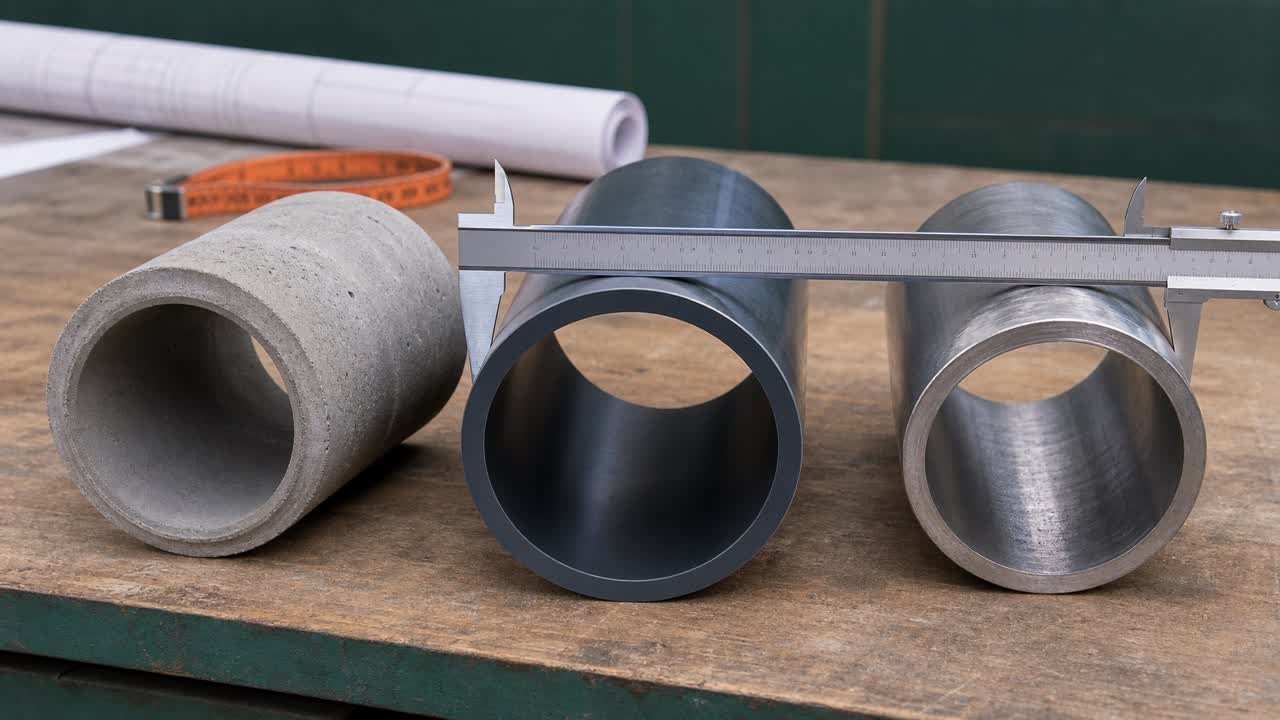
- Identify the pipe. Record the material, product, verified outside diameter, joint type, invert, crown, and springline. Use the pipe outside diameter guide when the schedule gives only a nominal label.
- Mark every horizontal zone line. Common lines include the top of foundation, top of bedding, springline, crown, top of initial backfill, and final surface.
- Attach a material to each zone. Copy the material class, gradation reference, reuse rule, density basis, lift limit, and testing requirement from the governing documents.
- Find local geometry. Note bell holes, fittings, structures, concrete encasement, trench shields, sloped walls, undercut, groundwater controls, and multiple pipes.
- Split changing sections. Start a new calculation section when width, depth, OD, zone cover, or material changes.
- Reconcile the result. The sum of all net fill spaces should equal gross excavation inside the same boundary minus permanent displacement.
The Trench Excavation Calculator can check a uniform rectangular gross trench. Use the changing trench measurement guide when the cross-section varies along the run.
Can the Drainage Gravel Calculator calculate every pipe zone?
The Drainage Gravel Calculator measures one rectangular aggregate envelope around a circular pipe. It combines the entered bed below the invert, pipe outside diameter, and cover above the crown, then subtracts the pipe displacement.
Use separate zone calculations when the governing detail assigns different materials or boundaries to bedding, haunch, primary backfill, initial backfill, and final backfill. One combined gravel-envelope result cannot show how much material belongs to each named zone.
| Quantity task | Method | Keep separate |
|---|---|---|
| One uniform aggregate envelope around one circular pipe | Drainage Gravel Calculator | Supplier density, loose-delivery conversion, allowance, and selling increment |
| Several named zones with different materials or limits | Zone-by-zone cross-sectional worksheet in this guide | Each zone boundary, pipe area inside that zone, material, and quantity state |
| Changing width, depth, OD, or zone height | Separate uniform sections or accepted surveyed sections | Station limits and the calculation method used for each section |
| Gross rectangular excavation | Trench Excavation Calculator | Pipe, bedding, structures, and material-state reconciliation |
| Multiple pipes, fittings, or structures | Separate geometry for every intersecting envelope | Spacing, shared boundaries, permanent displacement, and overlap checks |
Match all methods to the same station range and outer trench boundary before comparing totals. A zone worksheet should reconcile to gross excavation minus the permanent pipe and structure displacement inside that boundary.
How do you calculate each pipe-zone volume?
Calculate each zone from its cross-sectional area and represented length. Subtract only the part of the pipe that lies inside that zone.
Zone volume = net zone cross-sectional area × represented length
For a circular pipe divided exactly at the springline, the lower and upper halves each contain one semicircle of pipe displacement.
Full pipe area = π × outside diameter² ÷ 4
Semicircle area = π × radius² ÷ 2
For a rectangular trench with bedding ending at the pipe invert, primary backfill ending at the crown, and secondary initial backfill above the crown:
| Zone | Formula | Condition |
|---|---|---|
| Bedding | Trench width × bedding depth × length | The pipe barrel begins at the bedding surface |
| Haunch | (Trench width × pipe radius - lower semicircle area) × length | The zone runs from invert to springline |
| Primary backfill | (Trench width × pipe radius - upper semicircle area) × length | The zone runs from springline to crown |
| Secondary initial backfill | Trench width × cover above crown × length | The whole zone lies above the pipe |
| Final backfill | Trench width × final-zone height × length | The width remains rectangular through this zone |
A boundary that cuts through the pipe above or below the springline needs circular-segment geometry. Subtracting a full cylinder from a haunch-only zone removes pipe area outside that zone and gives the wrong material quantity.
Worked example: calculate 5 trench material zones
Assume a hypothetical project detail shows a 20 m uniform run, 0.80 m trench width, 0.40 m pipe OD, 0.10 m bedding below the invert, 0.15 m initial backfill above the crown, and 1.50 m total trench depth. These values demonstrate geometry and do not prescribe an installation.
The pipe radius is 0.20 m. Each half of the pipe occupies a cross-sectional area of π × 0.20² ÷ 2 = 0.0628319 m².
| Zone | Calculation | Net volume |
|---|---|---|
| Bedding | 0.80 × 0.10 × 20 | 1.6000 m³ |
| Haunch | (0.80 × 0.20 - 0.0628319) × 20 | 1.9434 m³ |
| Primary backfill | (0.80 × 0.20 - 0.0628319) × 20 | 1.9434 m³ |
| Secondary initial backfill | 0.80 × 0.15 × 20 | 2.4000 m³ |
| Final backfill | 0.80 × (1.50 - 0.10 - 0.40 - 0.15) × 20 | 13.6000 m³ |
| Total net fill space | Sum of the 5 zones | 21.4867 m³ |
Reconcile the total against excavation and pipe displacement
The gross rectangular trench is 0.80 × 1.50 × 20 = 24.0000 m³. The pipe displaces π × 0.40² ÷ 4 × 20 = 2.5133 m³.
Net fill space = 24.0000 - 2.5133 = 21.4867 m³
The independent result matches the sum of the zone quantities. A mismatch would point to a missing zone, double-counted boundary, wrong pipe deduction, or inconsistent section length.
Imperial cross-check
A second fixture uses a 100 ft run, 3 ft trench width, 2 ft OD, 0.5 ft bedding, 1 ft cover above crown, and 6 ft total depth. The 5 net zones total 1,485.8407 ft³, or 55.0311 yd³. The independent check gives the same result: 1,800 ft³ gross trench minus 314.1593 ft³ pipe displacement.
NIST Handbook 133, 2026 Appendix E supplies the exact relationship of 27 ft³ per yd³. Keep the calculation in one unit system until the final conversion.
Does pipe zone mean the same thing as embedment?
The governing document defines each collective term. One detail may include bedding, haunch, and initial backfill inside the embedment zone. Another may use pipe zone for the area from bedding to a named distance above the crown.
Record the lower and upper elevations beside the label. A quantity line that says only “pipe zone” cannot be checked until its boundary, trench width, pipe displacement, material, and represented length are known.
How do foundation, bells, and joints change the takeoff?
Foundation replacement sits below the normal bedding boundary and needs its own measured depth or approved undercut record. A bell, socket, coupling, flange, or structure can change the exterior envelope and the support detail over a short length.
| Condition | Quantity action | Required record |
|---|---|---|
| Unstable trench bottom | Measure approved over-excavation and foundation replacement separately | Inspection, station limits, depth, width, material, and approval |
| Bell or socket | Use the accepted bell-hole or local enlargement detail | Joint dimensions, spacing, and bedding requirement |
| Concrete cradle or encasement | Calculate its defined envelope and any partial circular segment | Approved cross-section, concrete limit, and pipe restraint procedure |
| Multiple pipes | Deduct each pipe and respect the specified spacing and shared zone boundary | Each OD, centreline, elevation, and trench width |
| Manhole, valve, or chamber | Split the route and prevent overlap between structure and trench quantities | Structure excavation, displacement, connection, and pay limits |
| Changing trench section | Calculate separate uniform segments or approved cross-sections | Stations, measured widths, depths, and method |
Can excavated soil be reused in every zone?
Reuse depends on the project specification, pipe system, soil classification, particle size, moisture, groundwater, placement access, and required compaction. Record excavated material as a candidate source until the responsible project process accepts it for a named zone.
The PPI drainage handbook discusses Class I, II, and III materials for the flexible-pipe zone it covers. WSSC Section 02315 assigns different materials and placement requirements by pipe type and zone. Apply each source only within its stated project and product scope.
Keep geometry and order state separate. A net compacted space of 21.4867 m³ does not by itself state the loose delivery volume, mass, truck count, supplier increment, handling allowance, or accepted payment quantity. The bank and loose volume guide explains how material-state conversions should be recorded.
What should a pipe-zone quantity record contain?
- Project, alignment, stations, drawing, detail, specification, and revisions.
- Pipe material, product, OD, joint, invert, crown, and represented length.
- Trench bottom, width basis, total depth, and upper surface.
- Foundation, bedding, springline, crown, initial-backfill, pipe-zone, and final-backfill elevations.
- Material class, source, gradation, moisture, lift, compaction, testing, and reuse status for each zone.
- Local bell holes, fittings, structures, encasement, multiple pipes, and changing sections.
- Gross area, pipe area inside each zone, net area, length, unrounded volume, and displayed volume.
- Bank, loose, or compacted state beside every material quantity.
- Supplier density, selling unit, allowance, and rounding only when separately supported.
- Preparer, checker, date, assumptions, unresolved questions, and approval route.
Common pipe bedding and backfill mistakes
- Using a typical detail from another agency as the current project's specification.
- Treating pipe zone, embedment, surround, and initial backfill as fixed synonyms.
- Using nominal pipe size in place of verified OD.
- Subtracting the full pipe cylinder from a partial haunch or cradle zone.
- Counting bedding beneath the barrel and the same space again as haunch material.
- Ignoring bell holes, joint enlargements, structures, and multiple pipes.
- Applying one trench width to zones with different side slopes or support systems.
- Combining compacted net space with a loose supplier quantity without a supported conversion.
- Adding an allowance before checking the base geometry.
- Rounding each short section before the project method calls for aggregation.
- Missing a negative final-backfill height caused by incompatible inputs.
- Letting the zone total differ from excavation minus permanent displacement without investigation.
Placement and safety checks
Quantity calculations do not approve a pipe installation. The project designer, accepted submittals, manufacturer instructions, invoked standards, inspection and testing plan, and responsible qualified people control materials, density, lifts, equipment, cover, groundwater measures, and acceptance.
NCDOT's Construction Manual tells its crews to spread and compact backfill at approximately equal heights on each side of the pipe to limit alignment and cross-section distortion. Apply that statement only within its project context and use the method required by the governing documents.
For U.S. construction work, OSHA trenching and excavation guidance covers cave-in protection, access, underground installations, water, atmospheres, falling material, inspections, and equipment near excavations. Workers should remain clear of material or equipment being lowered into a trench. Other countries use their own workplace rules.
Sources and source scope
- ASTM D2321-26: current scope and project-condition limits for buried thermoplastic gravity-flow pipe installation.
- Plastics Pipe Institute Drainage Handbook, Chapter 9: bedding, pipe zone, haunching, and flexible drainage-pipe placement context.
- PPI General Pipe Installation Procedures: stated bedding-to-final-backfill sequence for its PE context.
- WSSC Section 02315: one public utility definition set for bedding, haunching, initial backfill, pipe embedment, and final backfill, plus examples of pipe-specific material requirements.
- USDA-NRCS Washington Engineering Technical Note 8: a different select-backfill terminology example for its stated scope.
- NCDOT Construction Manual, Section 300-7: pipe-type checks, haunch placement, and equal-side backfilling in its construction context.
- NIST Handbook 133, 2026 Appendix E: exact cubic-foot, cubic-yard, and cubic-metre conversion relationships.
- OSHA Trenching and Excavation and 29 CFR 1926.651: U.S. occupational excavation-safety context.
Scope: the calculations show quantity geometry for stated example boundaries. The governing drawings, specifications, standard editions, accepted pipe data, soil and groundwater information, safety plan, testing, contract measurement rules, and responsible qualified people control the installation and accepted quantities.
Review note: Saleem Sial owns the research and editorial record. Source checks, independent fixtures, editorial review, build validation, link crawl, schema review, and rendered QA form the internal publication gate. Waseem Sial, External Reviewer and Engineer, remains listed for ongoing external review; no completed external-review date is claimed.
Return to the Earthwork & Drainage Calculators hub, or check which pipe outside diameter belongs in the calculation.