A fill compaction percentage has meaning only when the field result is tied to the correct material, laboratory reference, test method, lift, location and project requirement. A bare number such as 95% cannot show what was tested or whether the result represents the work.
Keep the full chain from the governing specification through failures and retests. This lets the responsible reviewer check the arithmetic and evidence without treating one spot result as approval of an entire fill area.
What should a fill compaction record prove?
The record should show which defined portion of fill was tested, which material and laboratory moisture-density relationship were used, what the field density and moisture results were, and how the responsible project party reached the stated decision.
Record the field dry density and the named laboratory maximum dry density beside the calculated ratio. Include the lab report ID, method, material source and any approved correction so another person can reproduce the result.
A complete record connects these items:
- Governing drawing, specification and accepted test-plan revision.
- Fill material identity, source, classification or approved zone.
- Laboratory report, compaction method and maximum dry density.
- Lift, lot, station or coordinates, elevation and test depth.
- Field test method, equipment record, tester and date.
- Wet density, water content, calculated dry density and relative compaction.
- Required density and moisture criteria, including the applicable rounding rule.
- Result, represented area, observation, corrective action and linked retest.
Use the Fill Dirt Calculator to estimate simple placed geometry. Its volume result does not establish the compaction requirement or prove acceptance.
Who sets the required compaction and testing frequency?
The governing project documents and responsible design, geotechnical or acceptance authority set the requirement. Confirm the named laboratory and field methods, percentage, moisture condition, lift thickness, lot definition, test frequency, location selection, correction process and acceptance role before work begins.
There is no universal 90%, 95% or 98% target for every fill. FHWA explains relative compaction with a specified laboratory test and notes that construction specifications may require minimum compaction and moisture conditions. Caltrans requires testing sufficient to determine compliance and says frequency can change with material and operation uniformity, borderline results and other project conditions.
Do not copy a test frequency, roller-pass count, lift thickness or moisture range from an online table. A project may divide foundations, embankments, utility backfill, pavement subgrade and landscape areas into different material zones with different controls.
What do the main density and moisture terms mean?
Field acceptance normally compares a dry field density with a maximum dry density obtained under a named laboratory compaction method. Moisture remains a separate measured condition even though it is also used to calculate dry density from a wet result.
| Term | Meaning | Record check |
|---|---|---|
| Field wet or total density | Measured mass or weight per total field volume, including the water in the sample | Method, equipment, units, location and raw result |
| Water content, w | Mass of water divided by dry mass of soil, usually reported as a percentage | Dry-basis definition, method, sample link and value |
| Field dry density | Dry soil mass or weight per total field volume | Wet density divided by 1 plus water content as a decimal |
| Maximum dry density, MDD | Peak dry density from the specified laboratory moisture-density relationship | Lab report, method, material, preparation, correction and revision |
| Optimum moisture content, OMC | Water content at the peak of that laboratory curve for its stated compaction effort | Use with the governing field moisture criterion, not as a universal allowable range |
| Relative compaction | Field dry density divided by the compatible specified laboratory maximum dry density | Both source values, units, formula, unrounded result and project rounding |
| Acceptance result | The responsible comparison with all applicable density, moisture and other requirements | Requirement source, decision authority, date and represented work |
FHWA distinguishes wet or total density from dry density and recommends obtaining moisture with the field unit-weight result. A field moisture value should not be replaced by the laboratory optimum value in the dry-density formula.
How do you calculate field dry density?
Divide the measured field wet density by 1 plus the dry-basis water content written as a decimal. Use consistent density units and retain enough digits for the later project rounding rule.
Field dry density = field wet density ÷ (1 + water content decimal)
Water content decimal = reported water content % ÷ 100
If field wet density is 126.0 lb/ft³ and water content is 10.0%, use 0.100 in the denominator:
126.0 ÷ (1 + 0.100) = 114.5454545 lb/ft³ dry
Entering 10 instead of 0.10 would divide the density by 11 and produce a meaningless result. The report should preserve the raw values and show whether software converted the percentage automatically.
How do you calculate relative compaction?
Divide the field dry density by the maximum dry density from the specified compatible laboratory relationship, then multiply by 100.
Relative compaction % = field dry density ÷ laboratory maximum dry density × 100
Worked imperial calculation
The following values are hypothetical arithmetic fixtures. They do not set an acceptance requirement.
| Stage | Calculation | Result |
|---|---|---|
| Field wet density | Measured input | 126.0 lb/ft³ |
| Field water content | 10.0 ÷ 100 | 0.100 |
| Field dry density | 126.0 ÷ 1.100 | 114.5454545 lb/ft³ |
| Matching laboratory MDD | Hypothetical lab input | 118.0 lb/ft³ |
| Relative compaction | 114.5454545 ÷ 118.0 × 100 | 97.0724191% |
No pass or fail is assigned. That decision still needs the governing target, moisture condition, method, material match and reporting rule.
Worked metric calculation
| Stage | Calculation | Result |
|---|---|---|
| Field wet density | Measured input | 1,995 kg/m³ |
| Field water content | 8.0 ÷ 100 | 0.080 |
| Field dry density | 1,995 ÷ 1.080 | 1,847.2222222 kg/m³ |
| Matching laboratory MDD | Hypothetical lab input | 1,900 kg/m³ |
| Relative compaction | 1,847.2222222 ÷ 1,900 × 100 | 97.2222222% |
The equation is unit-neutral when both densities use the same unit. Do not compare `kg/m³` with `lb/ft³` or convert one value with a rounded shortcut.
Why must the field material match the laboratory reference?
The laboratory maximum is specific to the sampled material, preparation and named compaction method. A different borrow source, blend, gradation, amount of oversized material, additive, processing delay or compaction effort can produce a different moisture-density relationship.
FHWA recommends establishing a moisture-density relationship for each major soil or mixture anticipated. The field record should identify the material and explain how the selected lab report represents it.
| Reference used with the same field dry density | Calculation | Reported ratio |
|---|---|---|
| Matching hypothetical MDD, 1,900 kg/m³ | 1,847.2222222 ÷ 1,900 × 100 | 97.2222222% |
| Unrelated hypothetical MDD, 1,820 kg/m³ | 1,847.2222222 ÷ 1,820 × 100 | 101.4957265% |
| Difference caused only by denominator | 101.4957265 - 97.2222222 | 4.2735043 percentage points |
The 1,820 kg/m³ value is intentionally unrelated. It demonstrates sensitivity, not a correction method. Stop the acceptance decision when the material-to-reference chain is uncertain and have the responsible laboratory or project professional resolve it.
Can a compaction result exceed 100%?
A calculated ratio can exceed 100% because it compares a field result with the maximum from one specified laboratory compaction effort. Review the record before accepting or rejecting the value.
- Confirm the field and laboratory density units.
- Check whether the correct material, source and lab report were selected.
- Confirm the specified laboratory compaction method and current report revision.
- Review oversize-particle treatment and any required correction.
- Check field moisture, dry-density arithmetic, transcription and project rounding.
- Review gauge standardization, calibration and material correction records where applicable.
- Confirm the test depth and prepared surface represented the intended lift.
- Ask the responsible testing and geotechnical personnel whether material variability or another approved explanation applies.
Do not cap a reported value at 100%, replace the denominator until the result looks ordinary, or hide it. Preserve the observation and disposition.
What location and lift details should be recorded?
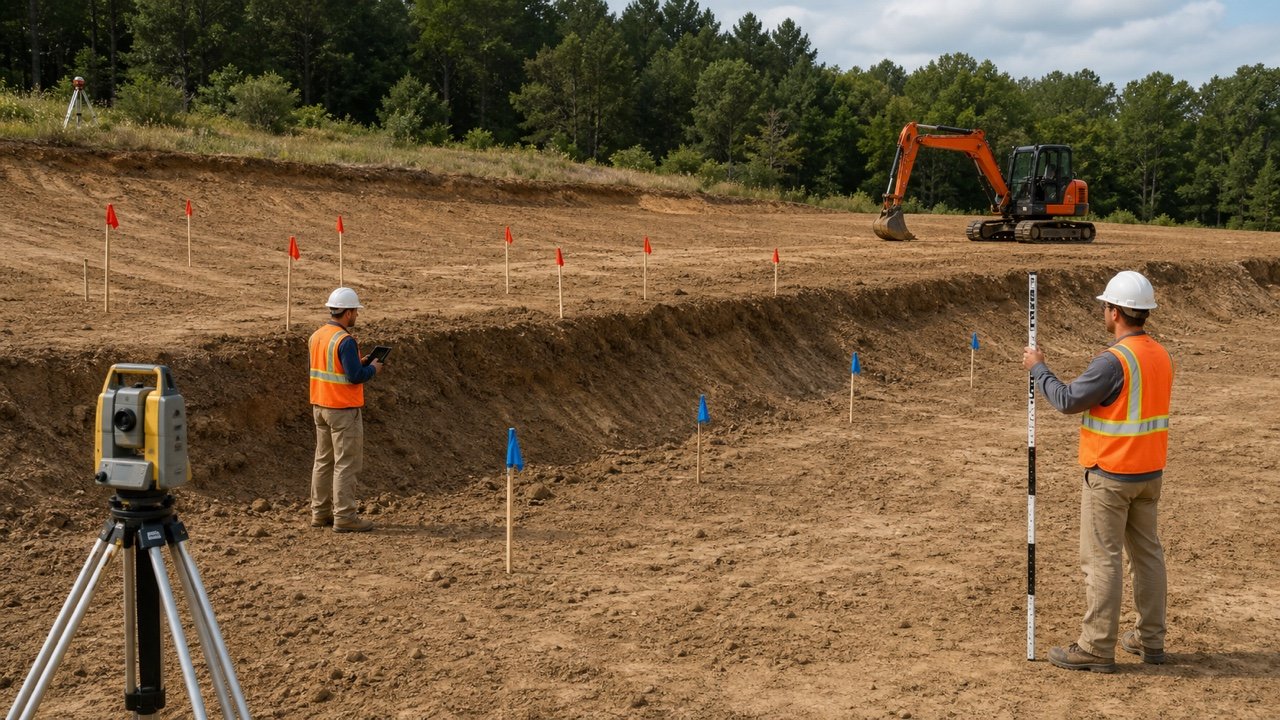
A test must be recoverable in 3 dimensions and connected to a defined portion of work. Record enough information for another person to locate the point and understand which lift and lot were open at that time.
| Record group | Fields to retain |
|---|---|
| Project control | Project, area, drawing and specification revisions, lot definition and acceptance plan |
| Horizontal location | Station and offset, grid, coordinates, pad or trench segment, with the reference system |
| Vertical location | Lift number, test depth, test elevation, lift surface elevation and datum or project reference |
| Material | Source, soil or aggregate ID, description, approved use, change boundaries and lab report link |
| Placement | Date, time, weather, lift placement window, observed processing, equipment and unusual conditions |
| Test | Unique test ID, method and edition, equipment ID, standardization or calibration record, tester and qualification |
| Results | Raw wet density, moisture, dry density, laboratory MDD and OMC, ratio, requirements and rounding |
| Disposition | Pass, fail or hold; represented boundary; instruction; correction; retest ID; reviewer and date |
NRCS requires representative test locations for the specific lift and calls for horizontal location and elevation to be documented. A photo can help when it shows the point in site context, but it should supplement coordinates, stationing or another controlled location record.
Does one passing test prove the whole fill?
One result describes one test location under its method. The accepted test plan, lot boundaries, testing frequency, observations and responsible decision determine how much work it represents.
Record material changes, wet pockets, edge zones, confined areas, equipment changes, interruptions, reworked sections and visibly weaker zones. NRCS advises testing the weaker identified section when processing or compaction differs. Caltrans states that nonuniform operations or borderline results can require more frequent testing.
Do not select only the firmest convenient spot or move a test away from the specified location without recording why. Random, stratified, directed and corrective test locations answer different quality questions and should be labelled accordingly.
Which field density method fits the material?
Use the method named by the project and confirm that the material and site condition fall within its scope. Method names are not interchangeable labels for the same observation.
| Method | What it can provide | Scope questions before use |
|---|---|---|
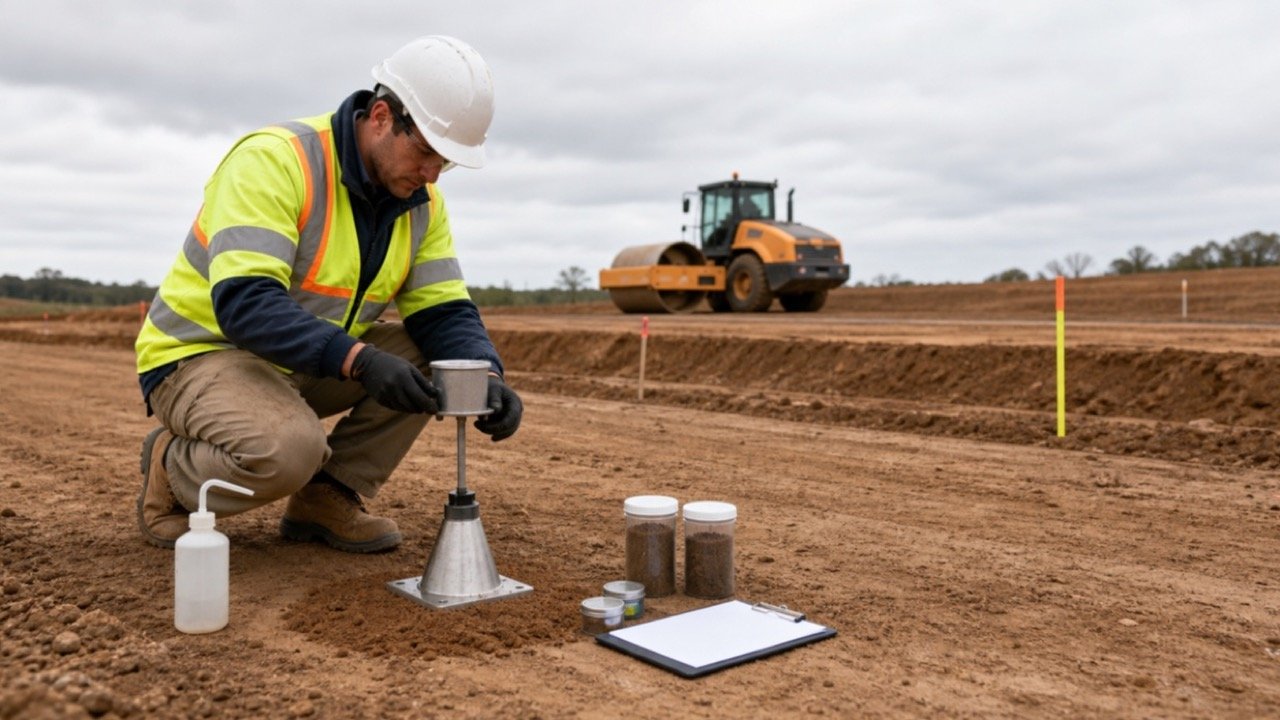
| Sand cone | In-place density from the mass of excavated soil and calibrated hole volume, with a linked moisture sample | Can the hole remain stable, and are coarse particles, saturation, plasticity and voids within the specified method scope? |
| Drive cylinder | In-place density from a recovered specimen of known volume | Can the material be sampled without unacceptable disturbance, refusal or particle-size conflict? |
| Nuclear moisture-density gauge | Shallow in-place density and water-content readings under the named method | Are the method, mode, calibration, standardization, material corrections, depth and radiation controls satisfied? |
| Low-activity or other approved method | Method-specific density or related field result | Does the project accept it, and is there a valid correlation, equipment record and qualified operator? |
| Rockfill or oversized-material procedure | Project-specific density, placement, method or performance evidence | Which approved method handles the particle size, test volume, segregation, voids and lift geometry? |
ASTM's public D1556 scope limits the sand-cone method in materials with appreciable coarse particles and in soils that cannot maintain a suitable test hole. The full current standard and project specification control the work. This page does not provide a field procedure.
What must be recorded for a nuclear gauge?
Keep the project-specified test details and all applicable radiation-program records. Caltrans refers to operator, supervision, storage and transportation requirements, while the NRC directs users to the device manual and the licence issued for that gauge.
- Gauge make, model, serial number and authorized organization.
- Operator identity, required training or authorization and applicable licence program.
- Current calibration, daily standardization and project correction records required by the method.
- Test mode, probe depth or geometry, count or reading identifiers and prepared test surface.
- Material, location, lift and any condition that can affect the measurement.
- Transport, storage, incident and radiation-safety records required by the regulator and licence.
Only authorized, trained personnel should operate or transport nuclear gauges under the applicable licence, method, manufacturer instructions and local law. Keep workers and the public outside the controlled activity defined by that program.
How should moisture be documented?
Record the measured field water content, its method and sample or reading link. Compare it with the exact project moisture requirement separately from the density ratio.
NRCS explains that water content converts wet density to dry density and can verify whether compaction moisture falls within a specified range. It also supports decisions about borrow moisture and drying material that is too wet for the stated work.
- Identify whether the value is dry-basis gravimetric water content or another moisture measure.
- Do not substitute laboratory OMC for measured field water content.
- Record sampling and sealing time when a physical sample could lose moisture.
- Link an alternate moisture method or correction to the density result it modifies.
- Keep rain, irrigation, drying, mixing and delayed testing in the field observation.
- When no moisture range is specified, do not invent one from the OMC.
Density can meet its numerical threshold while moisture, stability, material or another requirement remains unresolved. Record each acceptance condition separately.
How should a failed compaction test and retest be recorded?
Retain the original failure, define the area it represents, record the approved correction and link every retest to that failure. The audit trail should show what changed and which responsible person released the work.
- Assign a permanent test ID and mark the result as fail or hold under the stated requirement.
- Map the represented horizontal boundary, lift, elevation and adjoining work.
- Stop covering the affected work when the project procedure requires a hold.
- Record the observed material, moisture, processing, equipment and site conditions.
- Obtain the approved instruction for drying, wetting, mixing, removing, replacing, recompacting or further investigation.
- Record correction time, limits, method and responsible parties.
- Test at the location or distribution required by the approved retest plan.
- Link the new test ID to the original failure without deleting or overwriting it.
- Record release, remaining limitation and reviewer identity.
A passing retest at another convenient point does not automatically close the failed area. The record must explain why the new point represents the corrected work. Avoid averaging a failure with nearby passes unless the governing acceptance method explicitly requires that calculation.
Is proof rolling the same as density testing?
Proof rolling and density testing provide different evidence. A density test checks a local field result against the specified moisture-density relationship. Proof rolling observes gross soft, yielding or pumping response under the project's controlled loading procedure.
| Check | Useful evidence | What it does not prove alone |
|---|---|---|
| Field density and moisture test | Local density, moisture and relative-compaction result under the named method | Uniform support across the whole lot, deeper weak layers, drainage or long-term performance |
| Proof rolling | Visible gross yielding, pumping, rutting or nonuniform response under the specified operation | A dry-density ratio, compliance with every lift, or a laboratory material match |
| Placement observation | Material consistency, processing, lift coverage, equipment and changing conditions | A measured density or final engineering performance by itself |
| Survey or geometry record | Placed boundaries, elevations, lift surfaces and volume | Material compaction acceptance or stability |
FHWA states that proof rolling can reveal soft zones that passed density requirements and that it does not replace good compaction procedures and inspection. The project must define the vehicle, loading, observation criteria and corrective response.
What changes for oversized fill, rockfill and mixed materials?
Large particles, segregation, voids and changing blends can invalidate a small-volume method or an unrelated laboratory curve. Stop and use the material-specific procedure in the project documents.
- Map each material source, processing zone and change boundary.
- Check whether the laboratory specimen excluded an oversize fraction and whether a correction is required.
- Confirm the field test volume and method can represent the particle size.
- Record cobbles, rock fragments, voids, segregation and test refusal.
- Keep rockfill placement controls, trial sections, roller records, settlement or other performance checks separate from fine-soil density arithmetic.
- Do not blend passing results from different materials into one unexplained average.
A changed material may need a new laboratory relationship. FHWA specifically recommends a relationship for each major soil or mixture anticipated.
How do compaction records connect to fill quantity?
Quantity and acceptance records should cross-reference each other while preserving their different purposes. A measured compacted volume describes geometry; a field density result describes one test location and comparison.
| Record | State or purpose | Do not assume |
|---|---|---|
| Design fill volume | Proposed geometric requirement | It equals delivered loose volume |
| Bank excavation | Material before excavation | All cut is suitable for fill |
| Loose delivery or stockpile | Disturbed material before placement | Its cubic units equal accepted compacted fill |
| Accepted placed geometry | Surveyed or measured final fill boundary | Survey alone proves density, moisture or material compliance |
| Field density test | Local moisture-density acceptance evidence | One point creates a volume conversion or proves every cubic unit |
| Mass tickets | Commercial or haul mass record | Mass converts to volume without a matching state and density basis |
The Bank vs Loose Volume guide separates excavation, loose and placed states. The Cut and Fill Volume guide explains the geometric surface record. Reconcile these with test lots and accepted lifts rather than forcing them into one percentage.
Common fill compaction record mistakes
- Reporting only a percentage without field dry density and laboratory MDD.
- Using 95% as a universal target because it appears in a title or example.
- Comparing the field result with a laboratory curve for another source or blend.
- Using wet density directly in the relative-compaction numerator.
- Entering water content as 10 instead of 0.10 in the dry-density equation.
- Mixing density units or rounding every calculation stage.
- Omitting station, coordinates, lift, elevation or represented lot.
- Choosing an easy test spot while unrecorded weak or wet areas remain.
- Using a field method outside its material or test-hole scope.
- Letting unqualified personnel perform compliance tests or operate regulated equipment.
- Replacing a failed test with a passing retest and losing the original history.
- Moving the retest without documenting how it represents the corrected area.
- Calling proof rolling a density test or treating a spot density pass as proof of uniform support.
- Using a compaction percentage to convert bank, loose or placed volume.
- Covering a held lift before the responsible project party releases it.
What should the closeout compaction package contain?
Assemble an indexed record that allows a reviewer to trace every accepted lift and every unresolved exception. Use permanent IDs instead of relying on file names such as final-final-2.
- Approved specifications, drawings, geotechnical requirements and test-plan revisions.
- Material approvals, source changes, classifications and laboratory moisture-density reports.
- Current test methods, equipment, calibration, standardization, correction and qualification records.
- Lift and lot map with dates, elevations, material zones and placement observations.
- All field results, including holds, failures, cancelled tests with reasons and linked retests.
- Corrective instructions, completed work, release decisions and responsible signatures or approvals.
- Proof-roll, survey, drainage, unsuitable-material, undercut or other separate records required by the project.
- Open exceptions, limitations and work that the package does not certify.
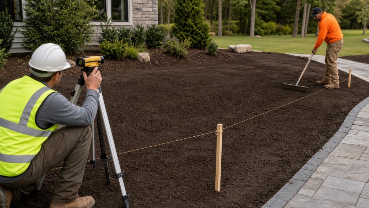
Keep landscape topsoil separate from structural or engineered fill. The Topsoil Settlement guide covers finished grade and growing-layer checks, not structural compaction acceptance.
Sources and source scope
- FHWA, Geotechnical Aspects of Pavements, Chapter 5: wet and dry density, moisture-density relationships, maximum dry density, optimum moisture and relative-compaction equations.
- USDA NRCS, National Engineering Handbook Part 645, Subpart H: Earthfill and Rockfill: representative lift locations, location records, field density and water-content methods, and inspection scope.
- Caltrans Construction Manual, Section 4-19 Earthwork and Section 6-3 Field Tests: project-controlled frequency, field-test records, qualifications and nuclear-gauge administration.
- FHWA, Geotechnical Aspects of Pavements, Chapter 8: lift monitoring, density testing and proof-rolling scope.
- ASTM International, D1556 sand-cone scope and D6938 course description: public method scope and reporting topics. Use the complete current project-specified standards for testing.
- U.S. Nuclear Regulatory Commission, Working Safely with Nuclear Gauges: U.S. licence, device-manual and radiation-safety boundary.
- USACE New England public project compaction report, October 1, 2019: one real field-record example used only to confirm practical traceability fields.
Source scope: these agency and standards sources explain terms, methods and controls inside their jurisdictions and project contexts. The governing project documents, current specified methods, material-specific laboratory evidence, applicable law, qualified testing personnel and responsible acceptance authority control the actual work. Every numerical example on this page is a hypothetical arithmetic fixture.
Return to the Landscaping Planning hub for fill dirt, topsoil, compost and mulch tools after the material role, geometry and acceptance requirements are defined.