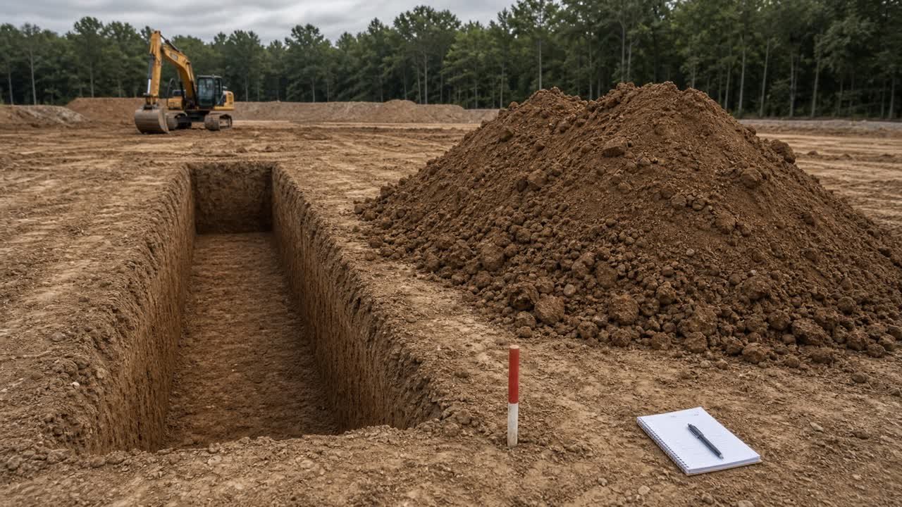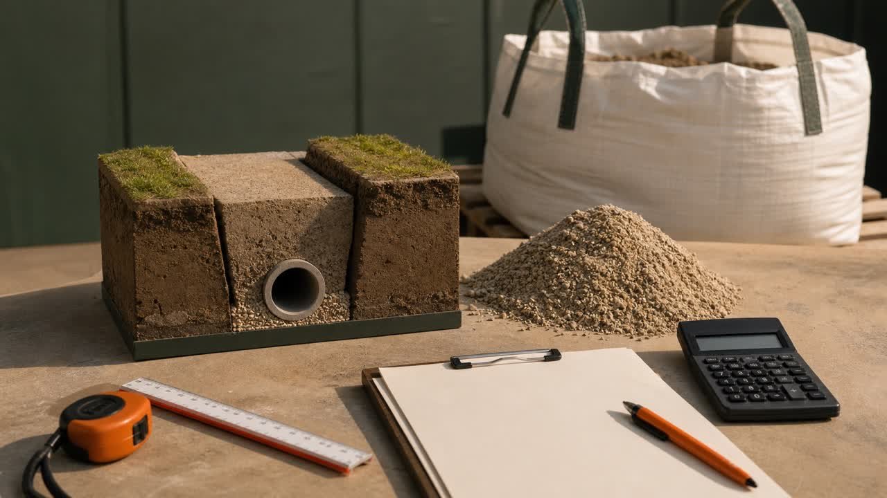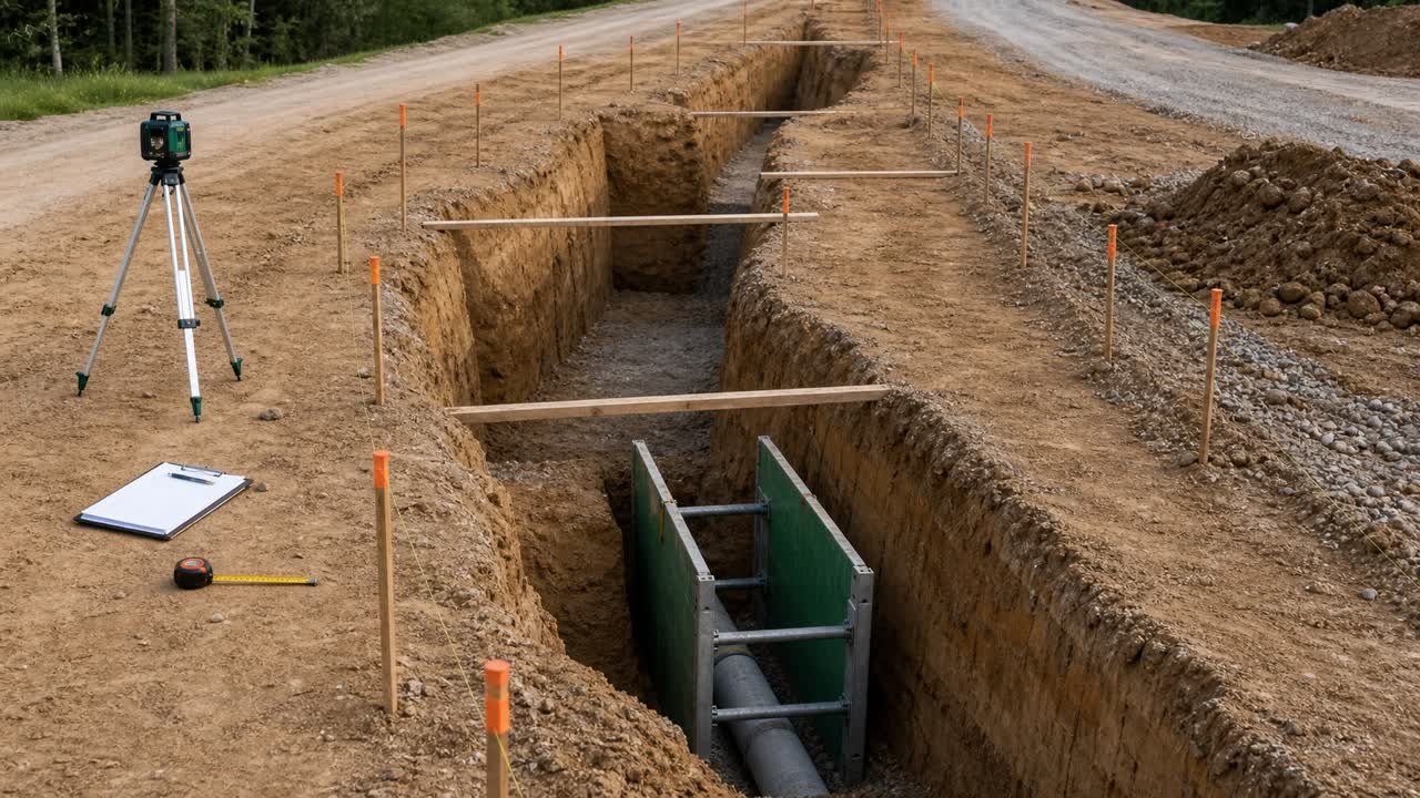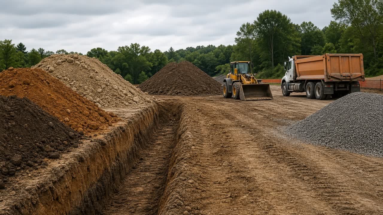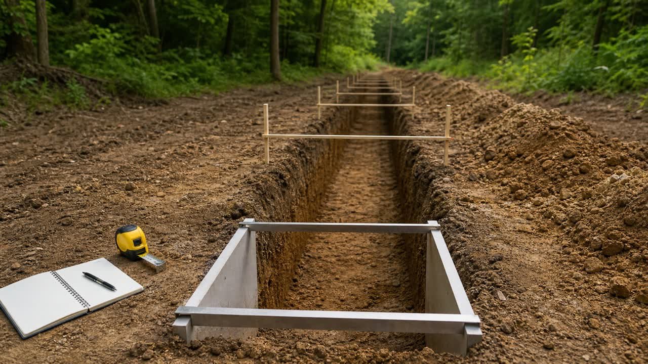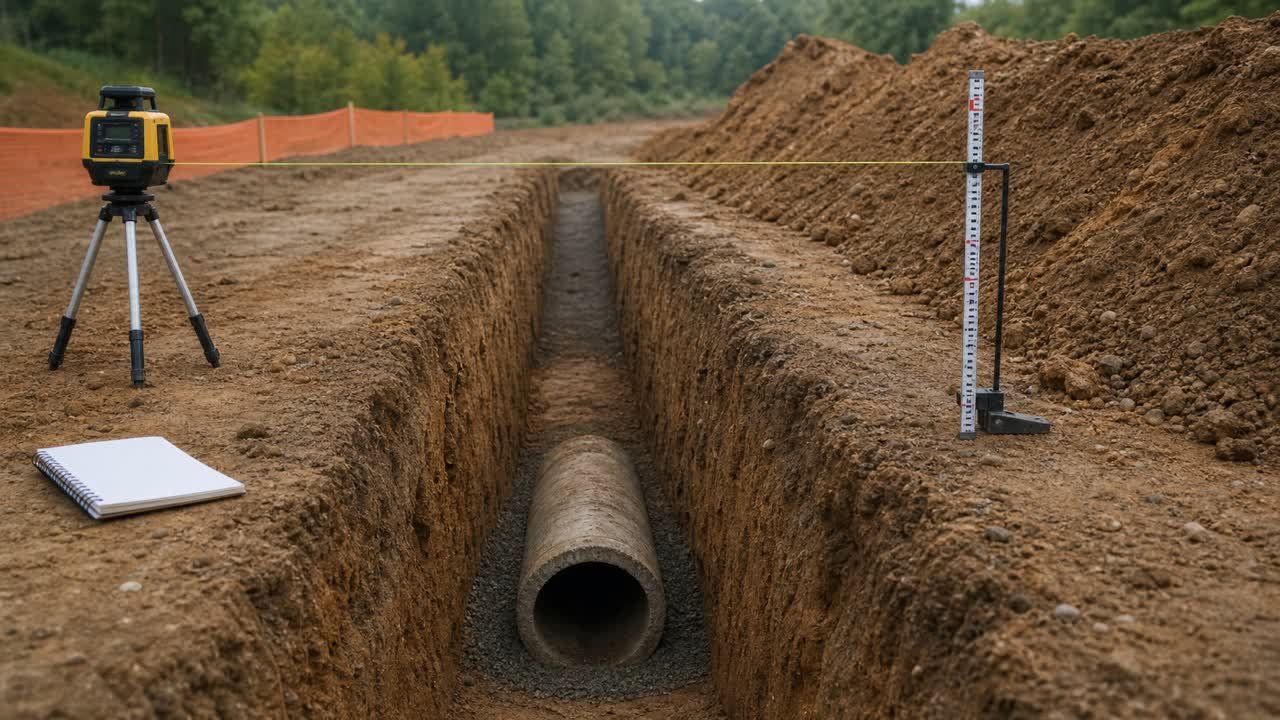
An invert elevation marks the inside bottom of a pipe or the stated bottom point of a drainage feature. Subtracting it from a ground or rim elevation gives depth to that invert at the same station.
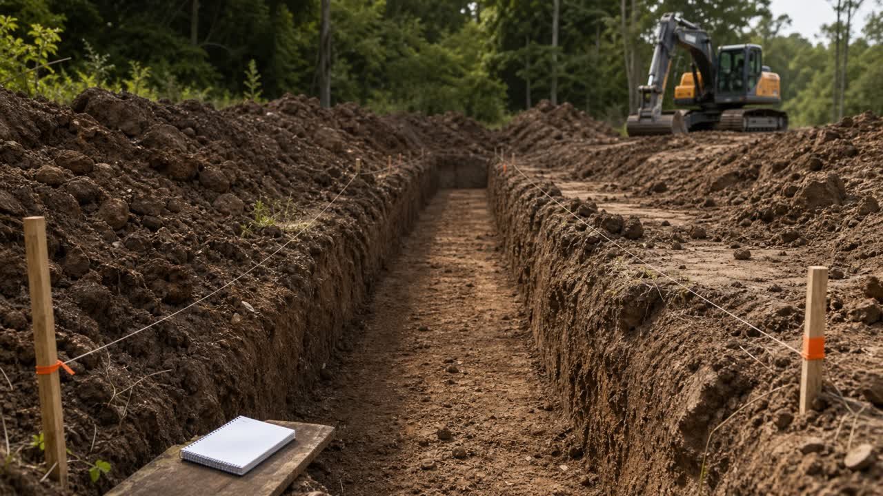
Full trench depth often extends below the invert. Pipe wall thickness, bedding below the pipe, foundation, undercut, or another approved formation detail can lower the excavation bottom.
How do you calculate trench depth from an invert level?
Subtract the pipe invert elevation from the controlling surface elevation to find depth to invert. Then continue from the inside invert to the outside pipe bottom and through each specified layer below the pipe.
Depth to invert = surface elevation - invert elevation
Full trench depth = surface elevation - trench-bottom elevation
A surface at station 0+040 cannot be paired with an invert at station 0+000. Existing ground, proposed grade, rim, and finished surface can also represent different vertical limits.
Enter the full excavation depth, rather than depth to the inside invert, in the Trench Excavation Calculator. Record which surface and bottom boundary the depth represents.
What is a pipe invert elevation?
For a circular gravity pipe, the invert is the elevation of the inside bottom of the pipe at a stated location. A drawing legend or schedule may use INV, IL, or another project abbreviation.
The U.S. Army Corps of Engineers HEC-RAS pipe-network documentation keeps invert elevation and terrain elevation as separate node attributes. It defines invert elevation as the bottom elevation of a node or culvert in that software context. Project drawings can use the term for a pipe, channel, structure, or trench feature, so confirm the label before calculating.
| Term | Typical meaning | Check before use |
|---|---|---|
| Existing ground | Surface present before the work | Survey date, station, offset, and whether stripping or prior excavation changes the start level |
| Finished or proposed grade | Designed final surface | Whether the depth or cover requirement is referenced to final construction |
| Rim or cover level | Top elevation of a manhole or inlet cover | Structure ID, frame adjustment, and whether rim equals the surrounding design surface |
| Pipe invert | Inside bottom of the pipe at the stated point | Incoming or outgoing pipe, station, datum, material, and barrel or connection location |
| Outside bottom | Lowest outside surface of the pipe section | Verified product geometry, bell, rib, corrugation, or barrel section |
| Trench grade or formation | Approved surface on which bedding, pipe, foundation, or another layer is built | Project detail, specification, and whether foundation or undercut sits below it |
Why is depth to invert different from full excavation depth?
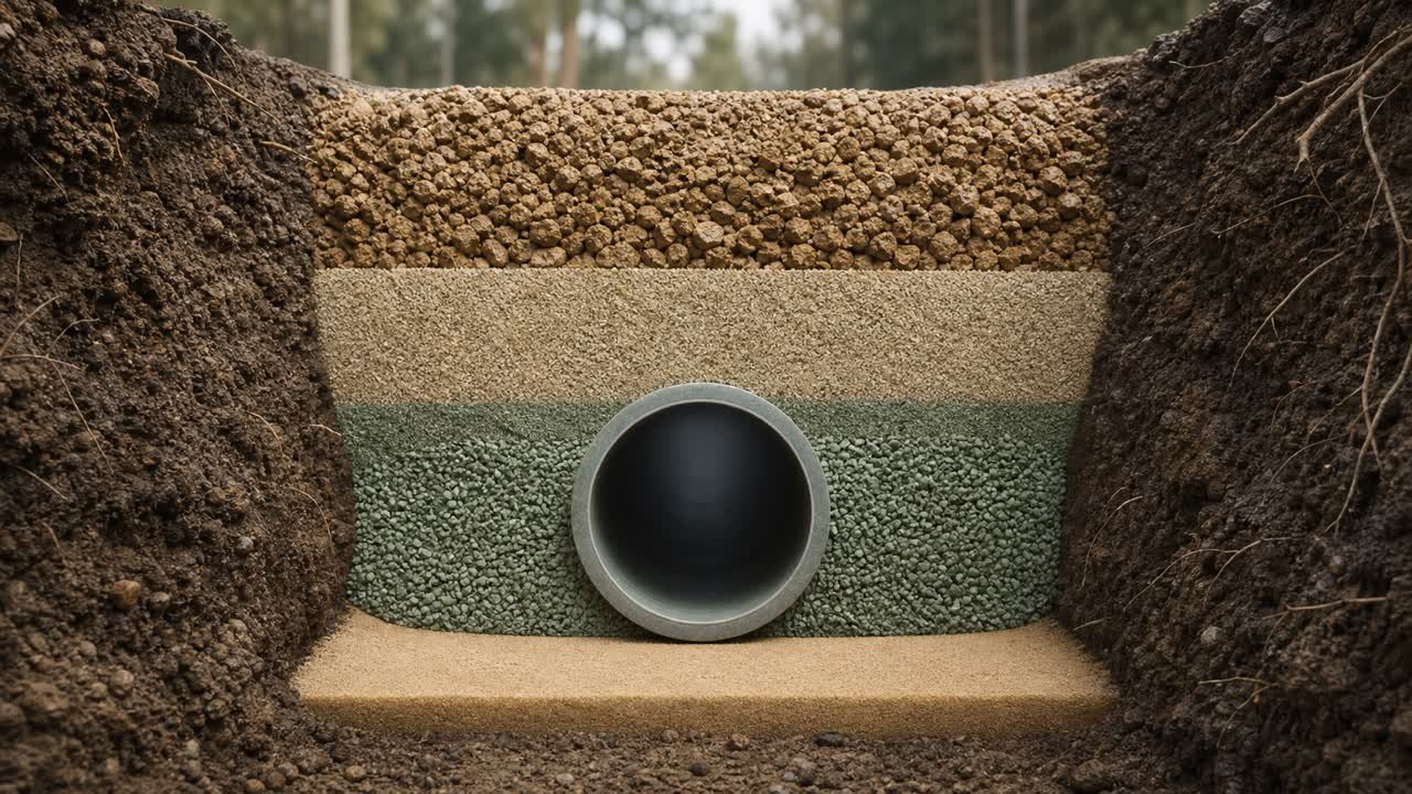
The invert lies on the inside pipe surface. Excavation can continue below that point through the pipe wall and the specified material beneath the pipe.
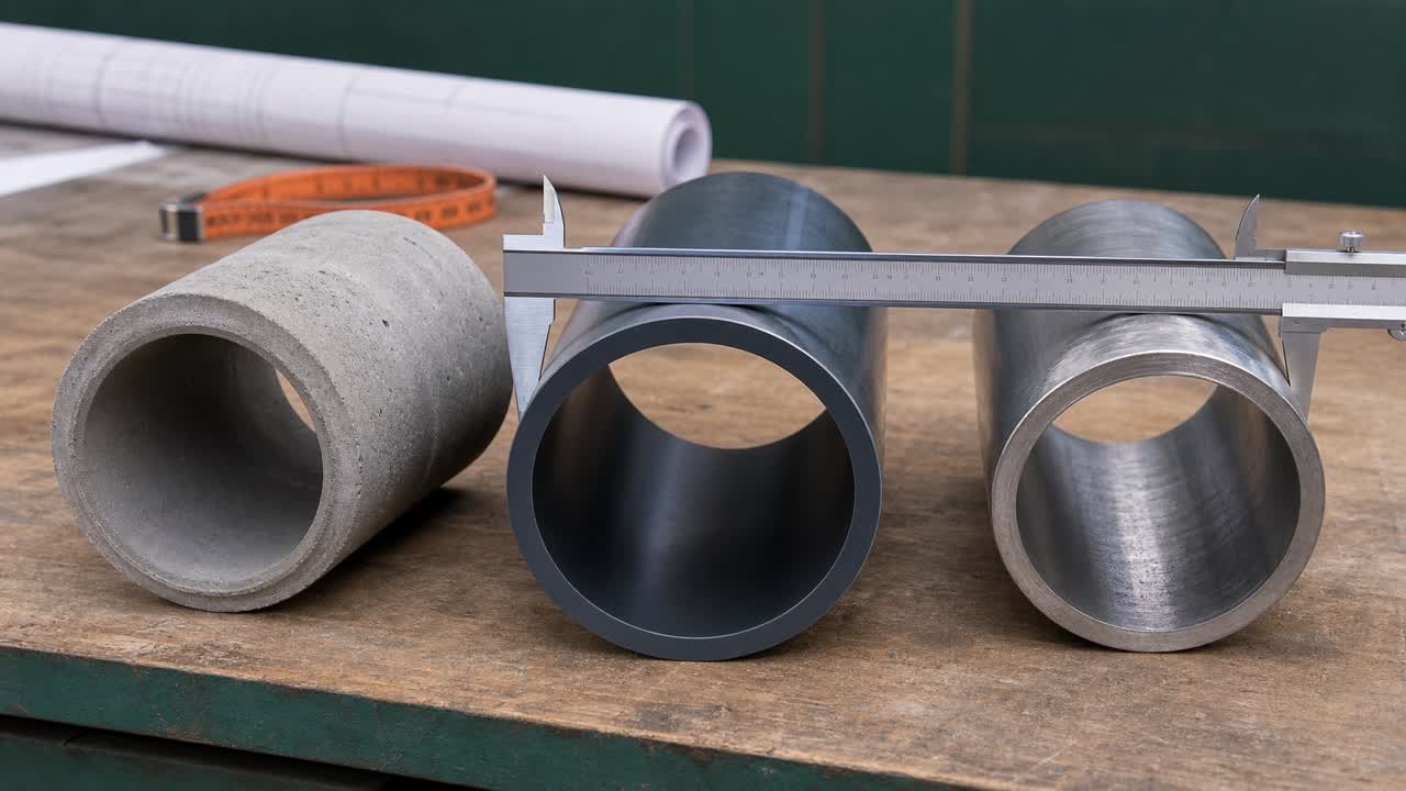
For a concentric circular pipe barrel with verified inside and outside diameters, half the difference between OD and ID gives the radial wall offset below the invert.
Offset below invert = (outside diameter - inside diameter) ÷ 2
Outside-bottom elevation = invert elevation - offset below invert
Trench-bottom elevation = outside-bottom elevation - bedding below pipe - additional foundation or undercut
Use dimensions for the exact product and section. Nominal size can differ from both ID and OD. Bells, ribs, corrugations, arches, channels, cradles, encasement, and structures need their approved profile or detail.
The pipe outside diameter guide explains why nominal size cannot replace verified dimensions in a quantity check.
Worked metric example
A profile gives a surface elevation of 102.400 m and a pipe invert of 99.850 m at the same station. The selected circular pipe barrel has a verified 0.600 m ID and 0.720 m OD. The detail shows 0.150 m of bedding below the pipe and no additional foundation.
| Step | Calculation | Result |
|---|---|---|
| Depth to invert | 102.400 - 99.850 | 2.550 m |
| Offset below invert | (0.720 - 0.600) ÷ 2 | 0.060 m |
| Outside-bottom elevation | 99.850 - 0.060 | 99.790 m |
| Trench-bottom elevation | 99.790 - 0.150 | 99.640 m |
| Full trench depth | 102.400 - 99.640 | 2.760 m |
The vertical-stack check gives the same result: 2.550 m to invert + 0.060 m pipe-wall offset + 0.150 m bedding = 2.760 m.
Worked imperial example
A station has a surface elevation of 512.80 ft and pipe invert of 507.35 ft. Verified barrel dimensions are 24 in ID and 28 in OD. The detail requires 6 in of bedding below the outside pipe bottom.
- Convert the diameters: 24 in = 2.0000 ft and 28 in = 2.3333 ft.
- Calculate depth to invert: 512.80 - 507.35 = 5.45 ft.
- Calculate the offset below invert: (2.3333 - 2.0000) ÷ 2 = 0.1667 ft.
- Calculate outside-bottom elevation: 507.35 - 0.1667 = 507.1833 ft.
- Convert bedding: 6 in = 0.5000 ft.
- Calculate trench-bottom elevation: 507.1833 - 0.5000 = 506.6833 ft.
- Calculate full trench depth: 512.80 - 506.6833 = 6.1167 ft.
The stack check is 5.45 + 0.1667 + 0.5000 = 6.1167 ft. Report a rounded depth only at the precision supported by the drawing and survey.
What if the drawing already gives formation level?
Use the approved formation or trench-bottom elevation directly when its definition matches the required excavation boundary. Subtract that elevation from the controlling surface at the same station.
Trench depth = surface elevation - approved formation elevation
Do not subtract bedding again when the stated formation already lies at the bottom of bedding. Check the section detail, notes, specification, and revision before deciding what the formation line includes.
FHWA drainage review guidance shows why this boundary needs a project definition. Its example uses different bottom or payment lines for different pipe and bedding conditions, and it requires engineer approval of excavation depth and cross-section.
How do bedding and foundation change trench depth?
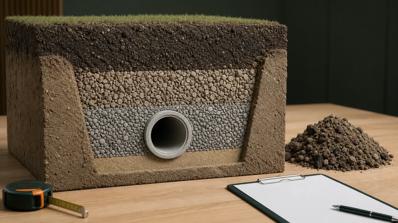
Bedding brings the trench bottom to the required pipe grade and gives uniform support. A foundation is a separate lower zone used when the native trench bottom cannot provide a firm working platform.
| Layer or boundary | Position | Depth treatment |
|---|---|---|
| Pipe invert | Inside bottom of the pipe | Start with the scheduled elevation |
| Pipe wall below invert | Between inside and outside bottom | Use verified product geometry |
| Bedding below pipe | Between outside pipe bottom and its specified lower boundary | Subtract the detail thickness from outside-bottom elevation |
| Foundation | Below bedding where required | Add only when the project detail or direction includes it |
| Undercut or stabilization | Extra excavation for unsuitable bottom conditions | Record as an approved separate quantity and revised boundary |
The Plastics Pipe Institute separates bedding from foundation in its PE-pipe installation terminology. Its guidance says foundation may be needed when native trench bottom lacks a firm platform. Product, soil, water, loading, and project requirements control the actual detail.
How do you calculate an invert between stations?
Use the approved starting invert, grade, direction, and horizontal run. Multiply grade as a decimal by run length to calculate the elevation fall.
Fall = grade % ÷ 100 × horizontal run
Downstream invert = upstream invert - fall, when the pipe falls downstream
Example: an upstream invert of 100.000 m falls at 0.50% over 40 m. The fall is 0.005 × 40 = 0.200 m, so the downstream invert is 99.800 m. At 20 m, the calculated invert is 99.900 m.
Use the sign and direction shown in the project record. Curves, vertical bends, structure drops, deflections, and differing distance conventions need the approved alignment or model. This calculation checks a stated grade; it does not design the pipe slope.
Why can trench depth change along a constant pipe grade?
Surface elevation can rise or fall at a different rate from the pipe invert. Calculate both elevations at matching stations before finding depth.
| Station | Surface elevation | Invert elevation | Depth to invert |
|---|---|---|---|
| 0+000 | 102.40 m | 100.00 m | 2.40 m |
| 0+020 | 102.55 m | 99.90 m | 2.65 m |
| 0+040 | 102.30 m | 99.80 m | 2.50 m |
Add the pipe-wall and below-pipe layers at each station to obtain full excavation depth. Split the volume calculation where the cross-section or depth changes. The changing trench sections guide explains representative stations and average end-area calculations.
How do you close a trench-depth station record?
Calculate full depth by 2 paths before releasing a station schedule. One path subtracts the derived trench-bottom elevation from the surface. The other adds depth to invert, the verified pipe offset, and each approved layer below the pipe.
Closure difference = full depth by elevation subtraction - full depth by vertical stack
Use unrounded values for both paths. A nonzero closure difference points to an arithmetic, unit, sign, datum, station, pipe-dimension, or layer-boundary problem. The project controls the acceptable survey and construction tolerances; this arithmetic check supplies no universal tolerance.
| Station | Source control | Surface | Invert | Derived trench bottom | Surface - bottom | Vertical stack | Closure |
|---|---|---|---|---|---|---|---|
| 0+000 | Profile R4, datum A | 102.40 m | 100.00 m | 99.79 m | 2.61 m | 2.40 + 0.06 + 0.15 = 2.61 m | 0.00 m |
| 0+020 | Profile R4, datum A | 102.55 m | 99.90 m | 99.69 m | 2.86 m | 2.65 + 0.06 + 0.15 = 2.86 m | 0.00 m |
| 0+040 | Profile R4, datum A | 102.30 m | 99.80 m | 99.59 m | 2.71 m | 2.50 + 0.06 + 0.15 = 2.71 m | 0.00 m |
This ledger continues the station example with a 0.060 m pipe-wall offset and 0.150 m bedding below the outside pipe bottom. If the pipe product, detail, surface source, or revision changes, start a new controlled row or segment rather than carrying the old offset forward.
Which surface elevation should you use?
Use the surface that defines the top of the measured excavation under the project method. Record its name, station, offset, date, and revision.
- Use existing ground when the takeoff measures excavation from the pre-work surface.
- Use an approved stripped or prepared surface when prior removal has a separate quantity.
- Use proposed or finished grade when checking final cover or a design profile that defines depth from that surface.
- Use rim elevation for a structure depth only when the schedule and structure definition call for it.
- Use a surveyed actual surface for an as-built comparison when the measurement procedure accepts it.
One route can need more than one surface record. A road fill, cut, stripped topsoil, temporary working platform, and finished pavement can all have different elevations at the same station.
How should trench depths feed the volume calculation?
Use full excavation depths at representative stations and keep abrupt changes in separate sections. A simple average of the start and end depths works only when the cross-sectional area changes linearly between those points under the approved method.
- List matching surface, invert, pipe, and formation data at each station.
- Calculate full excavation depth without rounding intermediate elevations.
- Add stations at grade breaks, structures, crossings, width changes, and different support or bedding details.
- Calculate the approved cross-sectional area at every station.
- Use the required section or surface method to calculate volume.
- Keep design, actual, accepted, and pay boundaries in separate records.
Use the trench volume per linear foot or metre guide for uniform sections.
Common invert and trench-depth mistakes
- Entering depth to invert as the full excavation depth.
- Pairing surface and invert elevations from different stations.
- Mixing local datum, project datum, and national elevation records.
- Using incoming invert when the calculation needs outgoing invert.
- Ignoring a structure drop or pipe offset.
- Using nominal pipe size as ID or OD.
- Subtracting the full outside diameter below invert instead of the verified radial offset.
- Subtracting bedding twice when formation already means bottom of bedding.
- Leaving required foundation or approved undercut out of the excavation boundary.
- Using proposed grade as existing excavation surface without checking the work sequence.
- Applying endpoint depth across changing ground.
- Rounding elevations before subtraction.
- Using the calculation to select a pipe grade or protective system.
What should a trench-depth record contain?
- Project, route, structure, pipe, station, offset, drawing, and revision.
- Datum, benchmark, coordinate system, and unit.
- Existing, stripped, proposed, rim, or surveyed surface elevation and its source.
- Incoming or outgoing invert elevation and its exact location.
- Verified pipe product, material, ID, OD, and section type.
- Bedding, foundation, undercut, cradle, or encasement boundary from the approved detail.
- Depth to invert, outside-bottom elevation, trench-bottom elevation, and full excavation depth.
- Unresolved labels, dimensions, conflicts, changes, and responsible clarification.
- Preparer, checker, date, and acceptance status.
Safety and scope
Read elevations from approved plans, models, schedules, and safe survey records. Do not enter an unprotected trench or structure to collect a depth.
OSHA's United States trenching guidance identifies cave-ins as the greatest trench risk and addresses protective systems, access, materials near the edge, water, atmospheric hazards, and inspection. This page performs elevation arithmetic. It does not approve excavation geometry, trench entry, shoring, shielding, sloping, benching, dewatering, utility support, or adjacent-structure protection.
Sources and source scope
- USACE HEC-RAS, Pipe Network Geometry: separate invert and terrain elevation attributes and node or culvert invert terminology.
- FHWA Drainage Guidelines, Generic Reviews: project approval, excavation-depth, bedding, bottom-line, and pipe-condition context.
- Plastics Pipe Institute, Chapter 7, Underground Installation of PE Piping, revised November 2025: pipe-trench terminology, installation scope, and site-specific or contractual limits.
- NIST Guide to the SI, Appendix B.8: exact inch, foot, and metre conversion relationships.
- OSHA Trenching and Excavation Overview: United States excavation hazard and protective-system context.
Scope: these sources support the terminology, unit conversions, layer distinctions, and stated safety boundary. The approved drawings, survey control, product data, specifications, contract, jurisdiction, and responsible people control the project elevations, excavation formation, pipe grade, bedding, foundation, and acceptance.
Review responsibility: Saleem Sial owns the published calculation, source, and editorial checks. Waseem Sial, External Reviewer and Engineer, remains listed for ongoing external review; no completed external-review date is claimed.
Calculate a uniform excavation with the Trench Excavation Calculator, return to the Earthwork and Drainage hub, or check design versus actual excavation volume after an approved as-excavated survey.