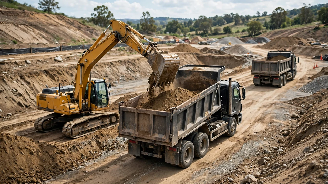
A grading stretch is in cut where existing ground sits above finished grade, and in fill where it sits below finished grade. This calculator takes the cut area and the fill area at two stations, plus the distance between them, and returns both volumes and their balance for that one interval.
How much cut and fill does this interval need?
Enter the cut area and fill area at station 1, the cut area and fill area at station 2, and the distance between the stations along the alignment. The calculator applies the average end area method to the cut areas and separately to the fill areas, then subtracts the fill volume from the cut volume. A positive balance is surplus cut. A negative balance is a shortfall. A zero balance means the interval balances on its own.
Run the calculation once per pair of stations. For a longer alignment, repeat it for each interval and add the interval volumes. Do not average areas across the whole alignment in one calculation.
| Result | Calculation | Volume state |
|---|---|---|
| Cut volume | (cut area 1 + cut area 2) ÷ 2 × distance | Bank volume, in its original position |
| Fill volume | (fill area 1 + fill area 2) ÷ 2 × distance | Compacted volume, as designed |
| Net section balance | Cut volume − fill volume | Section balance across two different states, so read it with the shrinkage note below |
| Loose volume of cut, when swell is entered | Cut volume × (1 + swell ÷ 100) | Loose volume for haulage |
| Bank volume required for fill, when shrinkage is entered | Fill volume ÷ (1 − shrinkage ÷ 100) | Bank volume that must be supplied to build the fill |
| Adjusted bank balance, when shrinkage is entered | Cut volume − bank volume required for fill | Like-for-like bank comparison |
When should you use this calculator?
Use it for one interval between two stations where both cross-sections are known and the ground changes gradually between them. The table below covers the cases that change the method.
| Project condition | Calculator method | Record to keep |
|---|---|---|
| Both stations in cut, or both in fill | Enter the areas for that side; enter zero for the other side | Station numbers and the section source for each area |
| One station partly in cut and partly in fill | Split the station at the daylight line and enter cut and fill areas separately | Both areas for the split station, so the two volumes are never averaged together |
| One end area is zero | The calculator uses the pyramid formula for that side: area × distance ÷ 3 | Which station reads zero, because average end area would overstate that side by half |
| Ground changes sharply between stations | Shorten the interval or use a surveyed volume; do not stretch one pair of sections across the change | Shorter interval stations and the reason the interval was split |
| Several stations along an alignment | Run each interval separately and add the interval volumes | A table of interval volumes, not one averaged result |
| Topsoil stripping, benches, or side slopes beyond the entered areas | Do not expect this calculator to add them | Separate quantities from the project method for those items |
Use the measure a site for cut and fill guide for the field readings behind these areas. Use the cut and fill calculation methods page when the average end area method does not fit the site, for example where a mid-section area is available for the prismoidal formula.
Worked example: one interval in metric units
Cut areas are 40 m² at station 1 and 60 m² at station 2. Fill areas are 10 m² at station 1 and 30 m² at station 2. The distance between stations is 50 m. No swell or shrinkage percentage is entered.
Cut volume = (40 + 60) ÷ 2 × 50 = 2,500 m³. Fill volume = (10 + 30) ÷ 2 × 50 = 1,000 m³. Net section balance = 2,500 − 1,000 = +1,500 m³, a surplus cut of 1,500 m³ for this interval. In litres, the cut volume is 2,500,000 L and the fill volume is 1,000,000 L.
Worked example: swell and shrinkage in imperial units
Cut areas are 200 ft² and 300 ft². Fill areas are 100 ft² and 100 ft². The distance is 100 ft. Swell is 25% and shrinkage is 15%, both from project geotechnical data.
Cut volume = (200 + 300) ÷ 2 × 100 = 25,000 ft³, which is 925.926 yd³. Fill volume = (100 + 100) ÷ 2 × 100 = 10,000 ft³, which is 370.370 yd³. The section balance is 15,000 ft³ before any state adjustment.
Loose volume of cut = 25,000 × 1.25 = 31,250 ft³ for haulage. Bank volume required for fill = 10,000 ÷ 0.85 = 11,764.706 ft³. Adjusted bank balance = 25,000 − 11,764.706 = 13,235.294 ft³ of bank surplus. The adjusted balance, not the section balance, is the like-for-like bank figure.
Worked example: a section tapering to zero
Cut areas are 0 m² at station 1 and 90 m² at station 2, with no fill at either station and a distance of 30 m. The calculator uses the pyramid formula for the cut side: 90 × 30 ÷ 3 = 900 m³. Average end area would have given (0 + 90) ÷ 2 × 30 = 1,350 m³, overstating the tapered section by 450 m³. The net balance is +900 m³.
How do you measure the inputs?
Take each area from a surveyed or designed cross-section at its station. The area is the cross-section area in cut, or in fill, measured in the plane of the section. Enter zero for a side that has no area at that station. A station that is partly in cut and partly in fill needs two areas, one for each side, split at the line where existing ground meets finished grade.
Measure the distance along the alignment between the two stations, not along the sloped ground surface. When the two sections differ sharply, add an intermediate station and run two shorter intervals. The average end area method is approximate: it treats the ground between sections as changing evenly, and the error grows as the end areas move apart.
What do bank, loose, and compacted volumes mean?
Bank volume is material in its original, undisturbed position. Excavation disturbs it, so the same material occupies more space as loose volume in a truck or stockpile. Placed and compacted as fill, it usually occupies less space than it did in the bank, except for solid rock, which can occupy more. The calculator keeps these three states in separate results and never converts one into another without a project percentage.
Swell is the percentage gained above the original bank volume on excavation. Shrinkage, as used here, is the percentage of bank volume lost on compaction, so compacted fill occupies (100 − shrinkage)% of its bank volume. Both percentages come from the project's geotechnical data. The page publishes no reference table for them, because the correct values depend on the material, moisture, and compactive effort on that project. A blank percentage leaves that stage out of the results.
Common mistakes
- Averaging cut and fill areas together into one volume, which hides both quantities and the balance.
- Using the slope length instead of the distance along the alignment between stations.
- Applying average end area to a section that tapers to zero at one station, which overstates that side by half.
- Ordering fill from the section balance without the shrinkage stage, which understates the bank volume the fill needs.
- Ordering haulage from the bank cut volume without the swell stage, which understates the loose volume trucks must carry.
- Using a swell or shrinkage percentage from another project, another material, or a generic table instead of project data.
- Treating the result as a payment quantity. Payment follows the project's survey method and specification.
See the common cut and fill mistakes page for the measurement errors behind these cases, the worked cut and fill example for a full site walk-through, and the cut and fill ordering page for haulage and delivery quantities once the volumes are known.
Limits and next steps
This calculator covers one pair of sections by the average end area method, with the pyramid correction for a zero end area. It does not cover grid or surface methods, prismoidal volumes that need a mid-section area, topsoil stripping, or haul truck counts and legal payload. Waste and contingency are separate project decisions and are not bundled into any result here.
Quantity planning does not replace structural design, excavation safety, project drawings, specifications, permits, codes, or a qualified professional. Use the material and soil considerations page before ordering from these volumes, and return to the Earthwork & Drainage Calculators hub for the related earthwork tools.
Sources and scope
- FHWA Earthwork Design: average end area method for excavation and embankment volumes; shrink and swell factors from project geotechnical data; excavation measured in its original position; accessed 2026-11-02.
- Engineering LibreTexts, 7.3 Earthwork: average end area, pyramid, and prismoidal formulas; accessed 2026-11-02.
- NIST Handbook 44 (2026), Appendix C: cubic-foot, cubic-yard, litre, and cubic-metre relationships; accessed 2026-11-02.
- NIST Guide to the SI, Appendix B: metric and US customary conversion relationships; accessed 2026-11-02.
Source scope: FHWA supports the average end area method and the requirement that shrink and swell factors come from project geotechnical data. LibreTexts supports the average end area, pyramid, and prismoidal formulas. NIST supports the stated conversions. Project drawings, specifications, surveys, supplier records, test data, local rules, and responsible people control the material, factors, order, transport, and work plan.
Review note: Calculation logic and independent automated fixtures passed internal review. Saleem Sial is the research and editorial owner. Waseem Sial's external review remains ongoing. The published page is indexable.