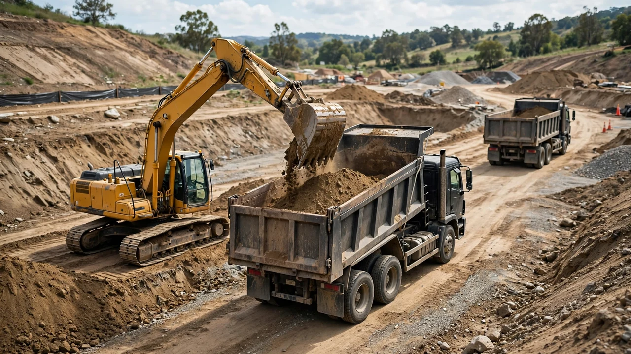
Three numbers feed every cut and fill calculation: the existing ground elevation, the proposed elevation, and the exact position where each pair was taken. Measure the existing ground yourself before any machine arrives, keep every reading tied to one protected datum, and record each point with its label, elevation, and date. A calculation built on guessed levels stays wrong no matter how careful the math is.
\nWhat do you measure for cut and fill?
\nRecord the existing ground level at each measurement point, read or computed from a known datum. Read the proposed level for the same position from the grading drawing or project documents. Note the horizontal position so the pair lines up on the plan. Cut is existing ground above proposed level. Fill is existing ground below proposed level.
\nOne datum serves the whole site. Every elevation, from the first grid point to the final as-built check, references the same benchmark. A second datum introduced halfway through silently shifts every depth.
\nWhich tools handle site levels?
\nA tape, wooden stakes, flagging, and a string line set out the grid on small flat sites. A builder's auto level with a leveling rod reads elevations to the millimetre or hundredths of a foot once the crew can see the rod through the instrument. A rotary laser level suits uneven ground where line of sight breaks. Survey-grade GPS or a total station fits larger sites where hundreds of points and a surveyor are already planned.
\nMatch the tool to the consequence of error. A garden terrace tolerates a tape and line level. A building pad with drainage requirements justifies the auto level. Keep the measuring range, resolution, and operator skill beside the reading when the quantity will be disputed or paid against.
\nHow do you set up a reliable datum?
\n- \n
- Pick one benchmark unlikely to move: an existing structure, a survey monument, or a long stake driven deep and protected by flagging. Do not use a loose rock, a pile of material, or a spot machines will cross. \n
- Record the benchmark's elevation, source, and date. If the elevation comes from a survey, keep the survey name and revision with it. \n
- Place the instrument where the benchmark and the first grid points are both visible, take a backsight, and confirm the instrument height matches the known elevation. Repeat the backsight after the first run of readings. \n
- Re-check the benchmark at the start of each work session and after any event that could move it, such as machine traffic or heavy rain. \n
Caltrans instructs project staff to verify planned ground surfaces and to field-check terrain changes that could affect earthwork quantities. A benchmark that moved since its elevation was set corrupts every depth tied to it.
\nHow do you set out and read a measurement grid?
\n- \n
- Divide the quantity boundary into cells with tape and string line. Small or rough ground needs a tighter grid; large smooth areas tolerate a wider one. There is no universal cell size, so record the size used. \n
- Drive a labeled stake at each grid intersection, A1, A2, B1, B2, and mark the grid on a sketch or the site plan. \n
- Read the existing elevation at each stake with the rod and level. Read each point once, then take a second reading on a sample of points to confirm the run. \n
- Write the proposed level beside the existing level at each point from the approved grading drawing. The difference is the depth: positive cut, negative fill. \n
- Close the run back to the benchmark at the end. If the closing reading disagrees with the known elevation, find the cause before using any of the readings. \n
Write "B4, existing 102.35 m, 2026-10-17" rather than a bare column of numbers. Unlabeled readings cannot be re-tied to the plan or re-checked after the ground is disturbed.
How do you measure a cross-section line?
\nRun the section line across the work, perpendicular to the alignment on linear projects. Stretch the tape along it and take elevation readings at fixed offsets, adding readings wherever the ground breaks sharply. Extend the readings beyond the cut or fill boundary on both sides so the day-one cross-section fully contains the work.
\nNumber the sections in order along the alignment, S1, S2, and record the station or chainage of each. Wyoming DOT uses this section-and-station structure for average-end-area earthwork quantities. Regular spacing keeps the calculation consistent; closer spacing on irregular ground keeps it honest.
\nWorked metric grid-cell example
\nOne 10 m by 10 m grid cell gives a plan area of 100 m². The measured depths at its four corners, existing minus proposed, are 0.6 m, 0.4 m, 0.8 m, and 0.6 m. All four corners are in cut.
\n- \n
- Add the corner depths: 0.6 + 0.4 + 0.8 + 0.6 = 2.4 m. \n
- Divide by 4 for the mean depth: 2.4 ÷ 4 = 0.6 m. \n
- Multiply by the cell area: 100 × 0.6 = 60 m³ of cut. \n
Result: the cell contains 60 m³ of cut. These depths are a hypothetical fixture, not a recommended excavation. Mixed cells, where corners carry both signs, are split at the zero-depth line before any cell volume is computed. The Cut and Fill Volume guide works through the full grid and section methods.
\nWorked imperial cross-section example
\nTwo adjacent sections, 25 ft apart, show cut areas of 48 ft² and 60 ft². No fill appears in either section.
\n- \n
- Average the two end areas: (48 + 60) ÷ 2 = 54 ft². \n
- Multiply by the distance between sections: 54 × 25 = 1,350 ft³. \n
- Convert to cubic yards: 1,350 ÷ 27 = 50 yd³. \n
Result: 50 yd³ of cut between the two sections. Repeat this for every adjacent pair and keep cut and fill totals separate. A zero area at one end still uses the same formula with the zero included.
\nWhich checks catch bad readings?
\n- \n
- Close every level run back to the benchmark and compare. A disagreement stops the work, not the record. \n
- Repeat a share of readings independently. If two crews read the same point, the comparison tests both. \n
- Confirm the benchmark elevation is current and the stake still stands before each session. \n
- Check that every grid point has both an existing and a proposed elevation before calculating. A missing pair is a gap, not a zero. \n
- Walk the site after reading and look for ground the grid missed: a ditch, a bank, or a pile the cell averages would hide. Add readings or breaklines there. \n
- Compare the measured surface against any earlier survey. Large unexplained differences need a field check, since Caltrans calls for verifying terrain changes that could affect quantities. \n
Common measurement mistakes
\n- \n
- Starting without a datum, or switching datums between sessions. \n
- Reading levels after stripping, machines, or rain have changed the surface the design was based on. \n
- Writing elevations without point labels, dates, or the instrument used. \n
- Using one grid size across flat and rough ground without adding points at breaks. \n
- Treating a single reading as final instead of closing the run to the benchmark. \n
- Assuming proposed levels from a drawing revision that has since changed. \n
- Feeding guessed or interpolated levels into a calculation and calling the result measured. \n
- Stopping the section lines short of the real cut or fill boundary. \n
- Mixing metric and imperial readings in one record without labeled units. \n
- Letting machines run over the benchmark or grid stakes before the record is closed. \n
What should the measurement record contain?
\n| Field | What it holds | Why it matters |
|---|---|---|
| Datum and benchmark | Benchmark description, elevation, source, date set | Every elevation ties to one reference |
| Grid definition | Cell size, grid origin, orientation | The calculation uses the real layout |
| Point record | Label, existing elevation, proposed elevation, depth sign | Each pair can be re-checked and recalculated |
| Instrument and crew | Level type, calibration or check date, readers | Precision and accountability are traceable |
| Drawing revision | Proposed-surface revision and date | Levels match the current design, not an old one |
| Closure and repeats | Closing benchmark reading, repeated points | Bad runs are caught before they feed the volume |
| Conditions | Weather, stripped or disturbed areas, exclusions | Later readers know what changed on site |
When the record is complete, the numbers move to the grid, section, and surface calculation methods. Keep the measurement record with the calculation so any depth can be traced back to a labeled point and a protected datum.
\nSafety and professional scope
\nMeasurement does not select excavation geometry, protective systems, equipment, or haul routes. Those decisions follow the project documents, applicable law, site conditions, and the responsible qualified people. Take readings from safe positions and keep clear of machine work while measuring.
\nFor U.S. construction work, OSHA identifies cave-ins as the main trench hazard, and OSHA 29 CFR 1926.651 covers access and egress, water accumulation, adjacent structures, and competent-person inspections. Other countries use their own workplace rules.
\nSources and scope
- \n
- FHWA Central Federal Lands, Earthwork Representation: Grading Summaries & Mass Haul Diagrams: earthwork components, adjustment, and plan-representation context. \n
- Wyoming DOT Survey Manual, Appendix F: cross-section, station, and average-end-area volume methods. \n
- Caltrans Construction Manual, Section 4-19 Earthwork: verify planned ground surfaces and field-check terrain changes affecting quantities. \n
- NIST Handbook 44, 2026 Appendix C: cubic-foot and cubic-yard relationships used in the examples. \n
- OSHA Trenching and Excavation and 29 CFR 1926.651: U.S. occupational excavation-safety context. \n
Scope: this page covers taking field measurements for cut and fill. The calculation methods, material-state conversions, and project acceptance rules live in the linked guides. Worked numbers are hypothetical fixtures. No grid size, instrument, or tolerance published here sets a project standard.
\nReview responsibility: Saleem Sial owns the published calculation, source, and editorial checks. Waseem Sial, External Reviewer and Engineer, remains listed for ongoing external review; no completed external-review date is claimed.
\nNext, use the Cut and Fill Calculator to work out the section volumes, then see the cut and fill volume methods guide for the calculation that uses these measurements, or return to the Earthwork & Drainage Calculators hub.
\n