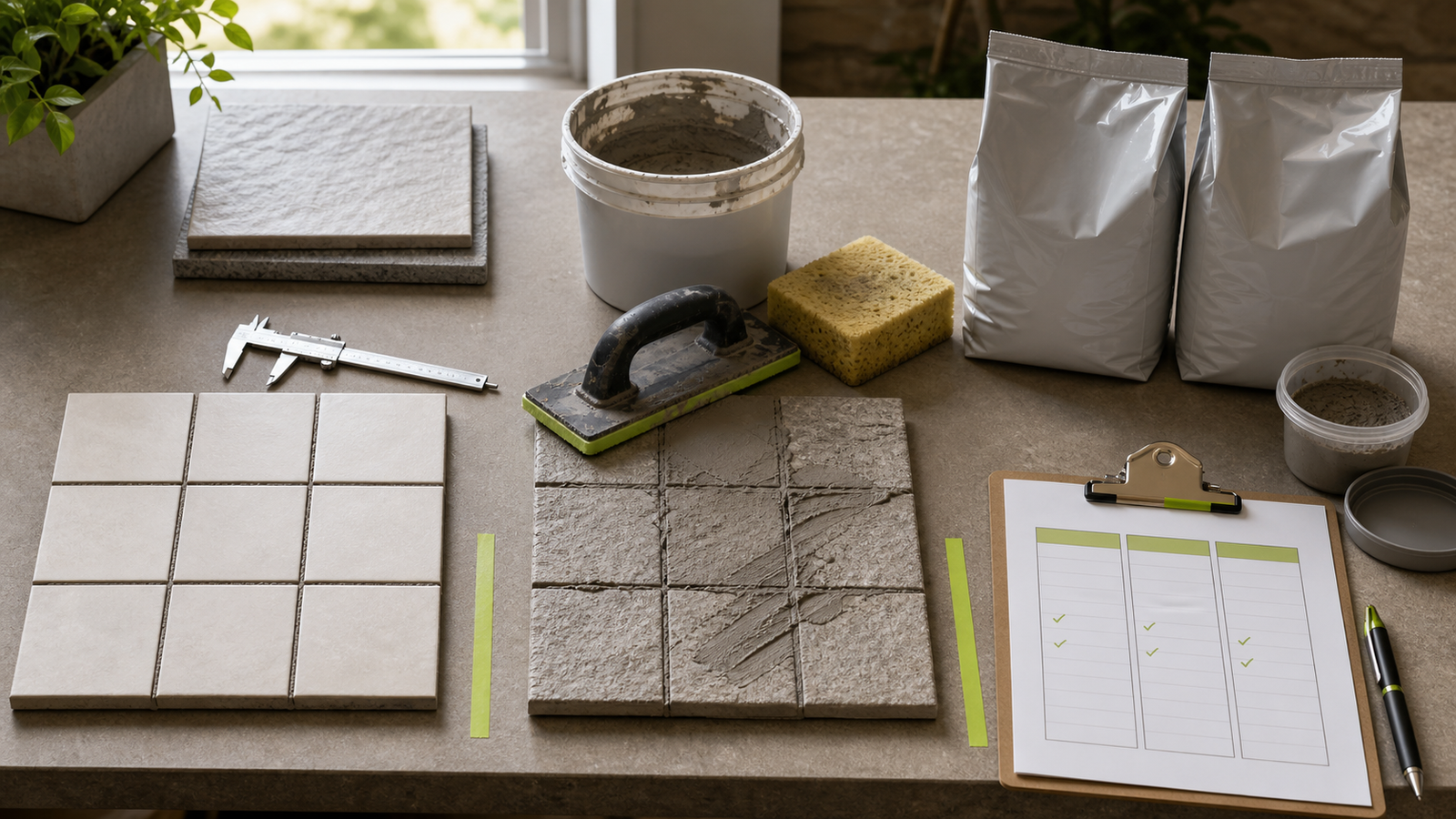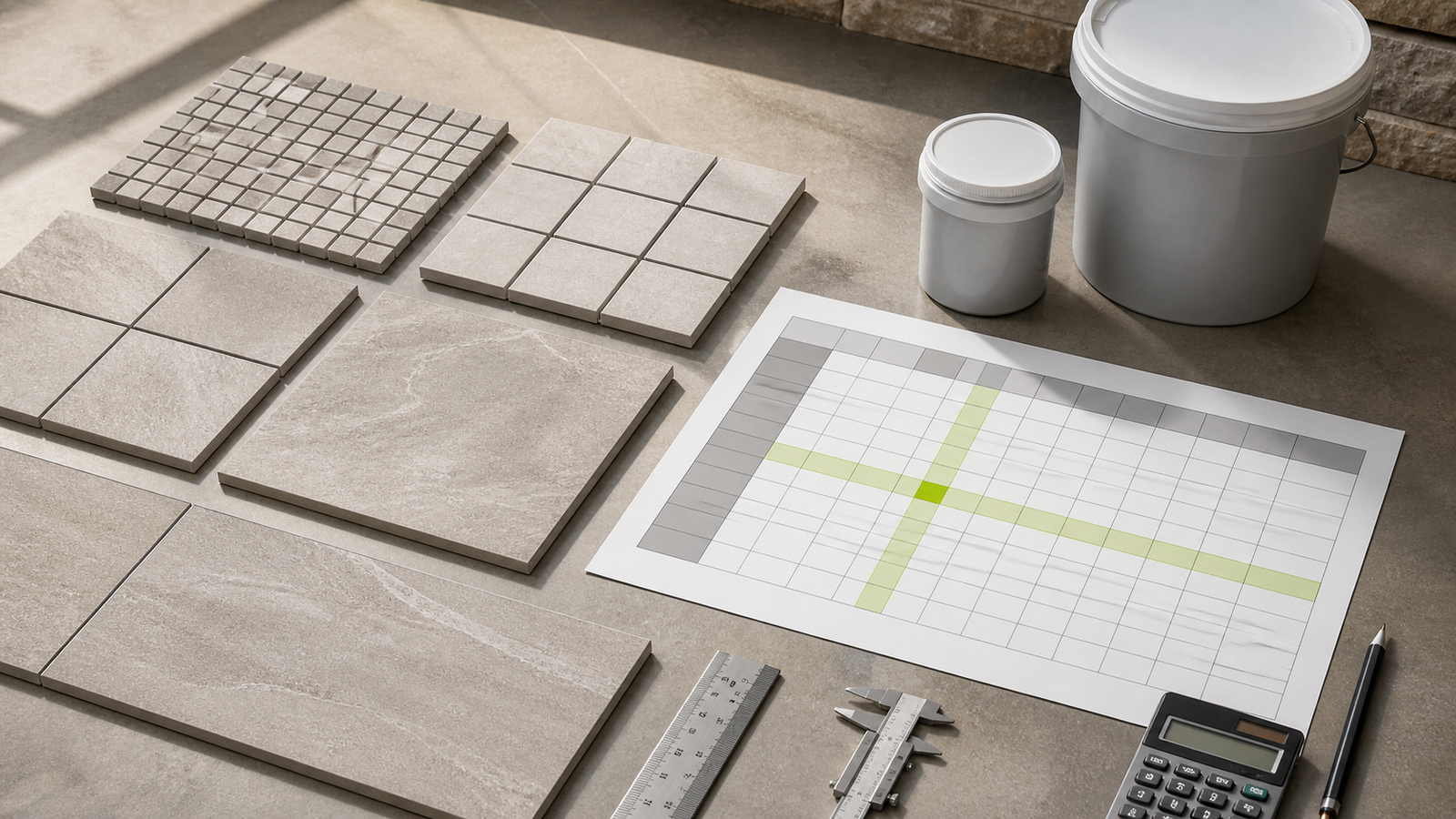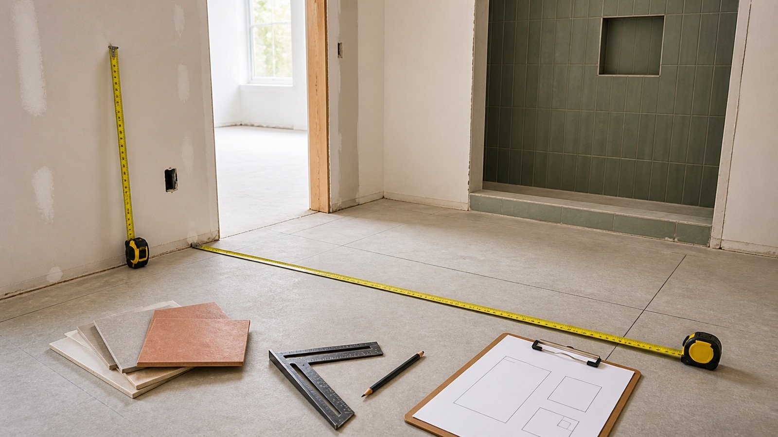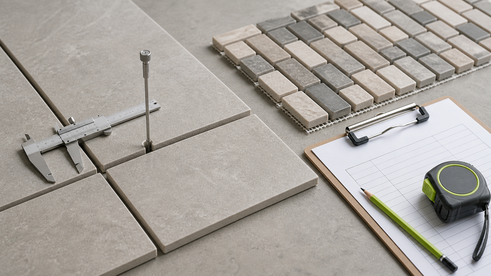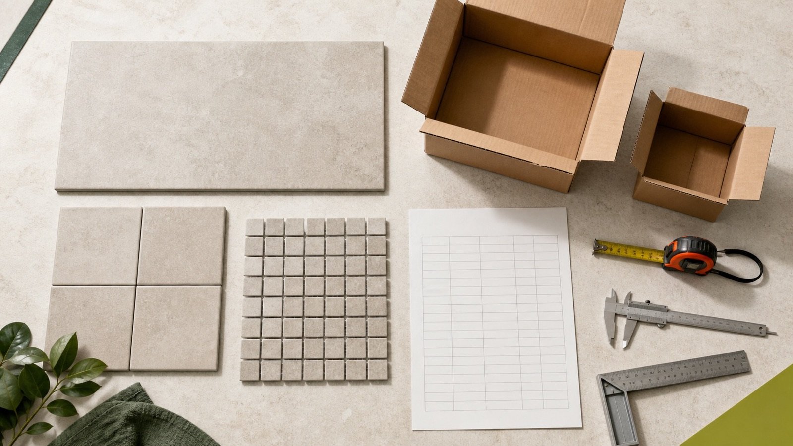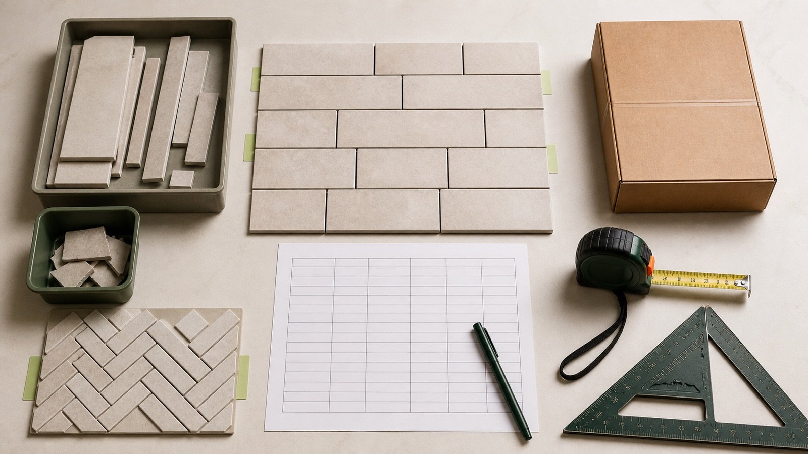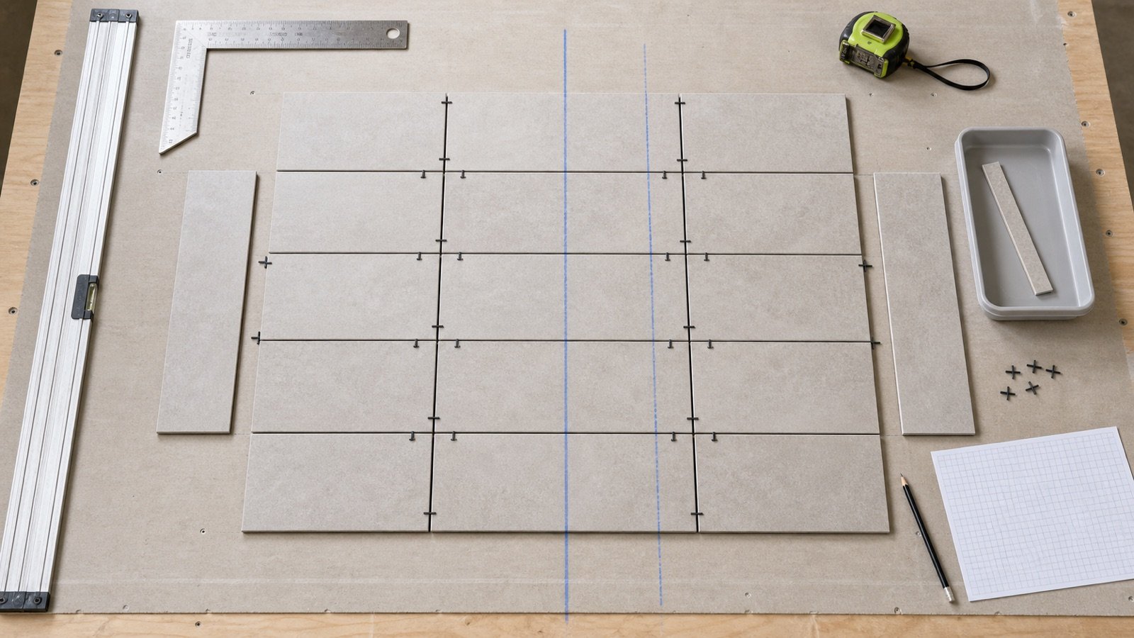
A tile layout needs a fixed field, verified tile dimensions, an approved joint width and a reference line that produces acceptable cuts. Record those inputs before adhesive makes the decision permanent.
Straight-grid arithmetic can compare start-line options. The final layout still needs a physical check against the actual walls, openings, trims, movement joints and selected product.
Where should you start a tile layout?
Start from a measured reference line that lets you compare the cuts at both ends of the tile field. A room centre line is a useful datum, but either a tile centre or a grout joint can sit on that line.
Compare both positions when one creates a narrow edge piece. Shifting the grid by half of one tile-plus-joint module can replace 2 small equal cuts with 2 larger equal cuts while keeping the field balanced.
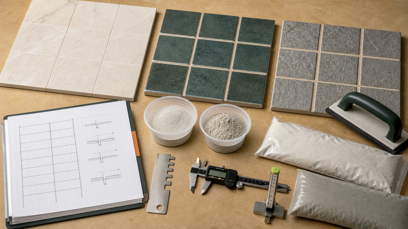
Dry lay representative tiles with the intended spacers, or mark a story pole. Check doorways, niches, drains, trims, visible edges and opposite walls before fixing tile.
The Tile Calculator handles measured area, tile count, allowance and cartons. Use this layout method to check where cuts fall; do not use area alone as proof that the pieces fit the chosen grid.
Which inputs belong on the layout record?
Record the field boundaries, selected product and installation decisions that change the repeating module. A nominal tile name or room area does not give a reliable start line.
| Record | What to capture | Why it changes the result |
|---|---|---|
| Tile field | Clear length and width between the chosen layout boundaries | Defines the distance filled by tile faces and internal joints |
| Tile face | Current product data plus sample measurements where required | Nominal and manufactured dimensions can differ |
| Grout joint | Approved width for the product and installation | Every internal joint adds to the row length |
| Movement joint | Specified position and width | It needs its own detail and cannot be replaced with grout |
| Pattern | Orientation, offset, repeat, shade and caliber records | Changes which pieces repeat and whether an offcut can be reused |
| Visible constraints | Doorways, niches, drains, corners, trims and focal lines | A balanced perimeter can still create a poor cut at a visible feature |
Use How to Measure for Floor and Wall Tile to close the surface ledger. Use Tile Sizes and Carton Coverage to keep actual face size, nominal name and carton data separate.
How does straight-row tile layout math work?
For a row with 2 equal edge pieces, subtract the full tile faces and the joints between all pieces from the clear field length. Divide the remainder equally between the 2 edges.
Equal edge cut = [field length − full tiles × tile face − (full tiles + 1) × grout joint] ÷ 2
Tile-plus-joint module = tile face + grout joint
The joint count is one greater than the number of full tiles because the row has a cut piece at each end. The calculation contains joints between adjacent pieces. Add no imaginary grout joint outside the last tile.
Keep specified perimeter gaps and movement joints on separate lines. Confirm which dimensions define the clear tile field before using the formula.
Worked example: which centred option gives better edge cuts?
A clear field is 2,630 mm wide. The verified tile face is 300 mm in the calculation direction, and the approved scenario joint is 3 mm.
| Line | Option A | Option B |
|---|---|---|
| Full tiles between edge pieces | 8 | 7 |
| Internal grout joints | 9 | 8 |
| Edge calculation | (2630 − 8 × 300 − 9 × 3) ÷ 2 | (2630 − 7 × 300 − 8 × 3) ÷ 2 |
| Equal cut at each edge | 101.5 mm | 253 mm |
| Start-line change | Original candidate | Shift 151.5 mm |
The 151.5 mm shift equals half of the 303 mm tile-plus-joint module. Both options are mathematically balanced. Option B has larger perimeter pieces, but the doorway, trim, drawing, pattern and installer review still control the choice.
CFI's ceramic installation workbook tells trainees to determine starting and grid lines after checking perimeter cuts. The Tile Association also tells installers to balance cuts, avoid small difficult cuts and match patterns at corners. Each source has its stated training or geographic scope.
Why must the joint count be exact?
A joint-width change repeats across the row. In the 2,630 mm example, 7 full tiles sit between 2 edge pieces, so the row contains 8 internal grout joints.
| Scenario joint | Combined joint width | Equal edge cut |
|---|---|---|
| 3 mm | 8 × 3 = 24 mm | 253 mm |
| 4 mm | 8 × 4 = 32 mm | 249 mm |
| 5 mm | 8 × 5 = 40 mm | 245 mm |
Each 1 mm increase removes 8 mm from the combined edge width, or 4 mm from each equal edge. These are arithmetic scenarios. Choose the joint from current product data, project requirements and the installation standard that applies to the work.
Worked example: how does a small imperial sliver appear?
A second field is 121.5 in wide. The tile face is 12 in and the recorded scenario joint is 1/8 in.
With 10 full tiles between the edge pieces, 11 joints use 1.375 in. The equal edge cut is only 0.0625 in: (121.5 − 10 × 12 − 11 × 0.125) ÷ 2.
With 9 full tiles and 10 joints, each edge is 6.125 in: (121.5 − 9 × 12 − 10 × 0.125) ÷ 2. Moving the start line by half of the 12.125 in module changes the edge condition. The 1/8 in input is not a recommendation for an unspecified tile.
How should a wall layout be checked?
Use level and plumb reference lines, then compare cuts at the floor, ceiling, inside corners, openings and fixtures. An uneven floor or ceiling should not become the datum for every row.
The Tile Association's wall-setting sequence begins from the lowest relevant base point, establishes a level line and uses a plumb centre line. It also calls for same-size cuts around windows where possible and pattern matching at corners.
Record the height at more than one station. A niche, trim profile or waterproofing termination can change which edge needs a full or substantial piece. Confirm those details before transferring a paper layout to the wall.
What changes when a wall or floor is out of square?
Keep one approved straight reference grid and measure the real boundary at several stations. The edge piece may need a taper even when the calculated centre cut is equal.
Example: the same field measures 2,630 mm, 2,624 mm and 2,637 mm at 3 stations. With 7 full 300 mm tiles and 8 joints at 3 mm, the theoretical equal cuts are 253 mm, 250 mm and 256.5 mm. A single straight grid cannot centre itself independently at every station.
Mark the fixed grid, record the cut at each station and check the narrowest point. Wall bow, trim thickness, finished clearances and the permitted cut method can change the usable piece.
How do patterns and product restrictions change the layout?
Use the selected manufacturer's current pattern sheet and installation instructions. Straight-row arithmetic cannot approve an offset, herringbone, modular or mixed-size repeat.
- Directional print or veining needs an orientation record for each reused offcut.
- Shade and caliber changes can alter appearance and the intended joint.
- Mixed sizes need a complete repeat, not separate rows calculated in isolation.
- Long rectangular products may limit the offset to control lippage risk.
- Trims, borders and mosaics need separate linear, piece or sheet schedules.
Marazzi's pattern document tells users to coordinate calibers, lay out at least 4 interlocking pattern samples and use no more than a 33% offset for the listed tiles with sides longer than 16 in. Daltile publishes its own large-format stagger and joint guidance. Treat both as manufacturer-specific instructions and verify the selected SKU.
Why are movement joints separate from grout joints?
Movement joints accommodate movement and use a specified flexible detail. Grout joints space adjacent tiles and receive the selected grout. Keep their locations and widths separate in the layout ledger.
CFI defines a movement joint as a space left open or filled with compressible material. TTA lists locations and dimensions within its British guidance. Current project drawings, local requirements and the responsible designer or installer decide the applicable movement-joint schedule.
Do not move, bridge or fill a structural, control or specified movement joint because the visual tile grid lands nearby. Stop the preliminary layout and obtain the required detail.
Which field checks close the layout decision?
Verify the drawing with representative tiles on the actual field. Record the approved option so the estimator, installer and owner are discussing the same line.
- Confirm the clear tile field and every excluded movement or perimeter joint.
- Measure representative tile faces and set the approved spacers.
- Mark perpendicular, level or plumb reference lines as the surface requires.
- Dry lay enough tile to expose the edge, doorway, opening and pattern conditions.
- Check the narrowest edge cut and each visible focal point.
- Record the option, orientation, joint, pattern, lot or caliber and approval.
- Transfer the resulting cut schedule to the Tile Waste Allowance ledger before ordering.
Photograph the dry layout and reference marks when the project record permits it. A later carton, product or layout change requires a new check.
Which common layout mistakes change the quantity?
Most quantity errors begin when a layout assumption remains hidden. Make each assumption visible before counting cut pieces.
- Using nominal tile size as the manufactured face size.
- Omitting the grout joint or adding a joint beyond every field edge.
- Starting from a room centre without comparing tile-centred and joint-centred positions.
- Counting a theoretical offcut as reusable without a destination and finished-edge check.
- Applying a generic pattern waste percentage instead of drawing the repeat.
- Treating a movement joint as a normal grout line.
- Checking one wall measurement in an out-of-square or bowed field.
- Changing product, joint or orientation without rerunning the layout and order.
What are the safety and specification limits?
This page compares preliminary dimensions. It does not approve tile cutting, substrate preparation, waterproofing, adhesive coverage, movement joints, structural details or code compliance.
For covered U.S. work, OSHA treats handheld tile saws as handheld power saws and stationary tile saws as stationary masonry saws under the construction silica standard. The applicable controls depend on the material, task, tool and workplace. Follow the current product and tool instructions and the employer's required exposure-control process.
Use a qualified tile professional for complex patterns, wet areas, large panels, heated floors, movement-joint design and surfaces that are not flat, level, plumb or square enough for the intended system.
Sources and review scope
The source list below supports the stated estimating, setting-out, manufacturer and safety boundaries. It does not turn a training example or one manufacturer's instruction into a universal project rule.
- The Tile Association, Tiling Guide: setting out, joint and movement-joint context within its stated UK scope.
- International Certified Flooring Installers Association, Ceramic Installation Workbook: drawing, grid-line and perimeter-cut training context.
- Marazzi USA, Pattern Layouts: Marazzi pattern, caliber, sample and offset notes.
- Daltile, Grout Joints for Large Format Tile: Daltile large-format stagger and joint guidance.
- NIST Handbook 44, 2026, Appendix C: unit relationships used in the checked examples.
- OSHA tile-saw standard interpretation and construction silica page: covered U.S. employer and tile-saw context.
Source scope: CFI supplies training methods; TTA supplies UK trade guidance; Marazzi and Daltile control only their stated products and instructions; NIST supports conversions; OSHA supports the U.S. worker-safety boundary. The 2,630 mm, 121.5 in and out-of-square examples are original checked arithmetic scenarios.
Review responsibility: Saleem Sial owns the research and editorial record. Source verification, independent arithmetic, build validation, link crawl, schema review and rendered QA form the internal publication gate. Waseem Sial, External Reviewer and Engineer, remains listed for ongoing external review; no completed external-review date is claimed.