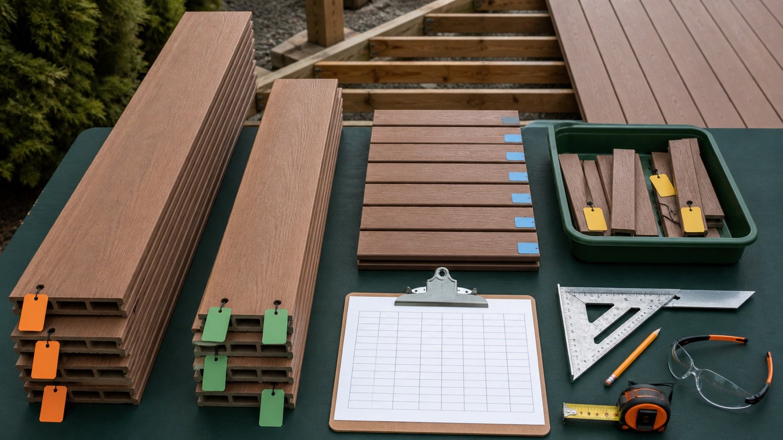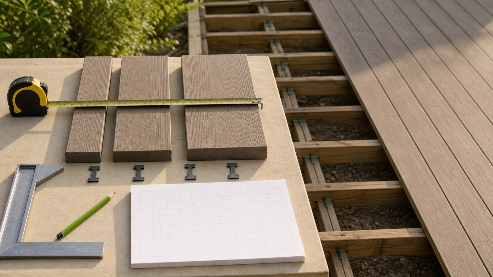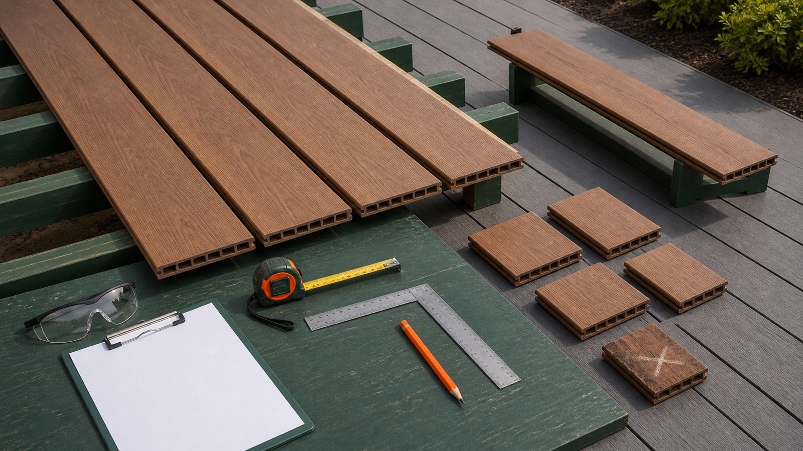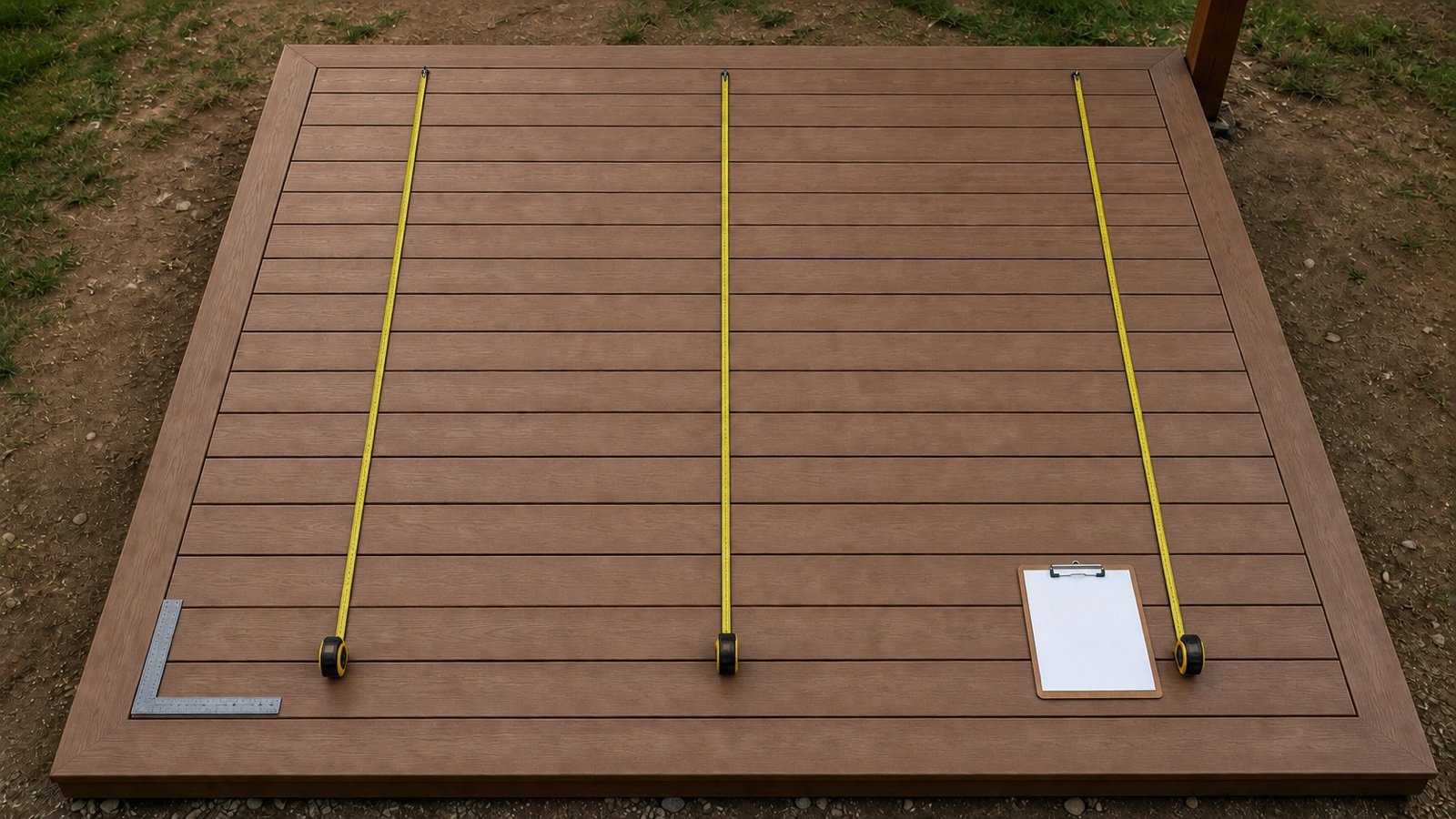
A deck surface can contain field boards, picture-frame borders, divider boards, posts and openings. One overall length and width can mix those parts and send the wrong dimensions to a board-row calculation.
Create a surface sketch first. Give every clear rectangular field its own run direction, run length and width across the rows. Keep borders and other components on separate ledger lines.
How do you measure a deck for deck boards?
Confirm the approved board direction, then measure each clear field in 2 directions. The board-run length follows the field boards. The clear field width crosses those boards and controls the number of rows.
Measure the width at the start, middle and end. Split the surface when a border, divider, opening, changed direction or different run length interrupts the field. Enter each accepted rectangular field separately in the Deck Board Calculator.
Do not enter the overall outside deck outline when picture-frame or divider boards occupy part of that surface. Schedule those boards separately.
Which measurements belong in the field ledger?
Record enough information to reproduce the field boundary and calculator entry. A number without its direction or reference edge is difficult to check.
| Field | What to record | Why it matters |
|---|---|---|
| Zone ID | A unique surface field or drawing reference | Keeps separate runs traceable |
| Board direction | Arrow on the plan or named reference edge | Defines run and across-row width |
| Run length | Clear distance parallel to field boards | Sets installed length per row |
| Width at 3 stations | Start, middle and end across the rows | Shows taper or nonparallel boundaries |
| Border or divider | Rows, face width, gaps and reference edges | Separates field from other boards |
| Posts and openings | Offsets, dimensions and edge treatment | Identifies cut and support conditions |
| Product record | Actual face width, approved gap and stock lengths | Completes the calculator inputs |
| Source and revision | Approved plan, field sketch or measured existing frame | Preserves the measurement basis |
Why must board direction be fixed first?
Run length and field width swap when board direction changes. The resulting area stays the same, but row count, stock-piece count, joint positions and cutoffs can change.
Board direction must also suit the approved supporting structure. TimberTech's current straight-layout guide tells users to confirm that the substructure is sound and correctly blocked and spaced before installing its decking. The quantity article cannot approve joists, blocking or board span.
Mark field-board direction, border direction and any centre divider on the same plan. A field on the other side of a divider may need a new run even when both fields use the same product.
What is the difference between the surface outline and clear field?
The surface outline follows the accepted outside edges of the finished decking. The clear field lies inside any picture-frame borders, divider boards, walls or other stated edge details.
A simple single picture frame uses separate boards around the field. TimberTech and Trex publish product-specific picture-frame instructions covering board edge type, overhang, fastening and blocking. Those details show why a border cannot be hidden inside a generic field allowance.
| Measurement basis | Use | Required follow-up |
|---|---|---|
| Outside finished surface edges | Overall outline and diagonal audit | Subtract the accepted borders and gaps to obtain the clear field |
| Outside framing edges | Existing-frame or approved-plan reference | Add or subtract only the specified overhang and edge detail |
| Inside edges of border boards | Direct clear-field reference | Confirm the field-to-border gaps are treated consistently |
| Wall, post or adjoining structure | Physical limit | Record the product-required clearance and cutting detail separately |
How do you measure a simple rectangular field?
- Identify the accepted field corners and reference edges.
- Mark the direction in which the field boards will run.
- Measure the clear run parallel to the boards at both field edges.
- Measure the clear width across the rows at the start, middle and end.
- Record any difference between repeated readings without averaging it away.
- Check both diagonals when the field is meant to be rectangular.
- Record actual board face width, approved internal gap and available stock length from the selected product and supplier records.
- Send the accepted run and width to one calculator entry.
Use one length unit through the ledger. NIST Handbook 44 records 1 ft as exactly 0.3048 m and 1 in as exactly 25.4 mm. Convert feet and inches before multiplying or comparing dimensions.
Why should width be checked at 3 stations?
A single reading can miss a tapered field, bowed edge or out-of-square frame. Start, middle and end readings show whether one rectangular-width input describes the surface.
Suppose the 3 readings are 132 5/8 in, 132 3/4 in and 132 1/2 in. Keep all 3 in the ledger. The approved layout may balance edge rows, trim boards individually or correct the boundary. An average of 132 5/8 in would hide the 1/4 in spread.
Row thresholds can make a small measurement difference material. With 5.5 in field boards and 3/16 in internal gaps, 21 rows cover exactly 119.25 in. A clear field just above that value needs another row unless the accepted edge layout changes the field.
What does a diagonal check prove?
Equal diagonals support a square-corner check for a rectangular boundary. Calculate the target diagonal with the Pythagorean relationship, then compare it with both measured corner-to-corner diagonals.
Target diagonal = √(length² + width²)
A 16 ft × 12 ft rectangle has a 20 ft target diagonal because √(16² + 12²) = 20. If measured diagonals differ, record both values and resolve the layout before relying on one rectangular calculator input.
Equal diagonals do not prove that every edge is straight or that the structure is sound. This is a geometry audit, not an inspection or structural approval.
Worked example: one picture-frame border
An approved finished surface outline is 16 ft × 12 ft. The layout has one picture-frame row on all 4 sides. For this checked fixture, the border and field board faces are 5.5 in and the accepted field-to-border gap is 3/16 in.
Because the overall dimensions are measured to the outside faces of the finished border boards, each clear-field dimension subtracts 2 border faces and 2 field-to-border gaps.
- Clear run: (192 − 11 − 0.375) ÷ 12 = 15.0520833 ft.
- Clear width: (144 − 11 − 0.375) ÷ 12 = 11.0520833 ft.
- Clear field area: 15.0520833 × 11.0520833 = 166.3568793 ft².
- At 5.5 in field-board face width and 3/16 in internal gaps, the field needs 24 rows.
- Installed field-board length: 24 × 15.0520833 = 361.25 ft.
- With 16 ft stock and no entered allowance, the no-pooling base is 24 boards and the pooled lower bound is 23 boards.
Entering the 16 ft × 12 ft overall outline as the field returns 26 field rows and 416 installed ft. That is 2 extra field rows and 54.75 ft above the correct field-board length. It still does not calculate the border boards.
The dimensions belong to this hypothetical fixture. Confirm the selected product, gap, border, overhang, fascia and framing details before using the same method on another deck.
How should an L-shaped surface be measured?
Split an L-shaped surface into non-overlapping rectangular fields at a clear reference line. Keep the fields separate when their run lengths differ, even if the product and board direction match.
Example: Zone A has a 4.8 m run and a 3.2 m width across rows. Zone B has a 2.4 m run and a 1.6 m width across rows.
| Zone | Run | Across rows | Area | Rows | Installed length |
|---|---|---|---|---|---|
| A | 4.8 m | 3.2 m | 15.36 m² | 23 | 110.4 m |
| B | 2.4 m | 1.6 m | 3.84 m² | 12 | 28.8 m |
| Ledger total | 2 different runs | 2 different widths | 19.20 m² | 35 field rows | 139.2 m |
The example uses 140 mm board faces, 5 mm gaps, 4.8 m stock and 0% allowance. Each zone needs its own calculator run. A 19.20 m² area total cannot preserve the 2 run lengths.
How should posts and openings be recorded?
Record each post or opening by offsets from 2 stable reference edges, plus its actual plan dimensions. Mark whether it lies inside the field, touches a border or creates a separate edge.
Do not subtract a small post area and assume the same reduction in boards. Rows may continue on both sides, and the cut board still consumes stock. TimberTech's straight-layout guide shows structural posts as a trimming condition and specifies a product-system clearance around adjoining structures or posts.
| Condition | Ledger treatment | Quantity implication |
|---|---|---|
| Small post inside field | Offsets, dimensions and cut detail | Usually a cut condition, not a simple area deduction |
| Large rectangular opening | Separate boundary and edge schedule | May divide rows or create shorter fields |
| Stair opening | Approved plan limits and edge components | Keep stair, trim and guard work outside field count |
| Centre divider board | Own board line and adjacent field limits | Creates separate run lengths or directions |
| Curved or diagonal edge | Coordinates, templates or checked layout | Outside the rectangular calculator |
When should you create another calculator entry?
Create another entry whenever one set of run, width, face, gap and stock inputs no longer describes the field.
- The board direction changes.
- A divider or border ends one run and starts another.
- The clear run length changes across an L-shaped surface.
- The product, actual face width or approved gap changes.
- The supplier stock length changes.
- A tapered or irregular boundary cannot be accepted as one rectangle.
Add the unrounded installed lengths and reviewed stock schedules after each field has been calculated. Do not merge the areas first and expect one row layout to return.
Which measurement mistakes change the board count?
- Entering outside surface dimensions as the clear field.
- Measuring to the frame edge without applying the approved overhang detail.
- Swapping the run and across-row width after board direction changes.
- Using one width reading on a tapered or out-of-square field.
- Averaging inconsistent readings before the layout is resolved.
- Counting picture-frame and divider boards as an unexplained allowance.
- Subtracting post area and assuming the cut board disappears from the stock order.
- Using nominal board width instead of actual face width.
- Applying a gap from another product or fastener system.
- Combining several run lengths into one area total.
- Rounding feet and inches before the field calculation.
- Using a surface measurement as a structural framing takeoff.
What should the completed measurement record contain?
- Project, deck or zone ID, location, date and drawing revision.
- Overall surface outline and its reference edges.
- Board direction, field run and start, middle and end widths.
- Both diagonal readings for each intended rectangular boundary.
- Picture-frame rows, divider boards, face widths, gaps and accepted overhangs.
- Posts, openings, walls, hatches, stairs and transition offsets.
- Manufacturer, product line, profile, actual face width and current installation guide.
- Available stock lengths, supplier record and selling increment.
- Separate calculator results, cut-plan status, allowance reason and final order approval.
- Measured by, checked by, open questions and field photographs.
Structural and safety limits
Measuring a board field does not inspect an existing deck or design a new one. It cannot approve joists, blocking, beams, ledgers, posts, footings, guards, stairs, connections, board span, fasteners or overhang.
The American Wood Council's DCA6 guide states that construction and materials must be approved by the authority having jurisdiction. The published DCA6 document is based on the 2015 IRC, so confirm the current local code, amendments, permits and accepted plans.
Existing decks can have decay, corrosion, loose connections or unstable surfaces. Control access and fall exposure before measuring. Follow the rules, product instructions and qualified inspection or design decisions that apply to the site.
Use the flooring-area measurement guide for indoor finish areas and package handoff. Return to the Decking planning hub for the current deck-surface workflow. The calculation methodology explains unit and rounding checks, and the corrections route accepts a formula or source issue.
Sources and source scope
- TimberTech CONCEALoc installation guide: one straight product-system example for actual face width, side gaps, post trimming, edge layout and framing prerequisites.
- TimberTech picture-frame guide: product-specific border, overhang, fascia, cutting and fastening context.
- Trex picture-frame guide: border-board identity, centre dividers, angled fields and separate blocking considerations.
- American Wood Council DCA6: structural and authority-having-jurisdiction scope. It does not approve a current local project.
- NIST Handbook 44 (2026), Appendix C: exact unit relationships used in the examples.
Source scope: the manufacturer pages show that field, border, gap, post and installation details depend on the selected system. AWC supports the structural and jurisdiction boundary. NIST supports unit relationships. These sources do not select the design, product, layout, allowance or installer for another project.
Review note: Saleem Sial owns the research and editorial record. Source checks, independent measurement fixtures, editorial review, build validation, link crawl, schema review and rendered QA form the internal publication gate. Waseem Sial, External Reviewer and Engineer, is listed for ongoing external review; no completed review date is claimed.