A roof-area measurement needs a boundary, a method and a slope state. Write those 3 items on every section before calculating. This prevents a horizontal plan dimension from being combined with a sloped face dimension or a pitch adjustment from being applied twice.
You can work from suitable drawings, safe ground measurements, direct sloped-face records or a checked measurement report. Choose the method section by section and keep the source beside each value.
Which roof measurements do you need for an area calculation?
You need the outer roof boundary, the dimensions of each non-overlapping section and either the pitch for each horizontal plan section or the actual dimensions of each sloped face. Include the horizontal projection of assigned overhangs in a plan method.
Record ridges, hips, valleys, eaves, rakes and openings on separate lines. Those lengths and counts can affect flashing, trim, starter, cap and cutting decisions, but they do not replace the roof-face area.
| Available record | Dimensions to collect | Pitch treatment | Use in calculator |
|---|---|---|---|
| Horizontal roof plan or ground projection | Plan length, plan width or shape dimensions to the outer covering boundary | Apply the section's rise/run multiplier once | Projection and pitch mode |
| Direct sloped roof face | Actual length and width along the surface, or other sloped-face shape dimensions | Already included in the face dimensions | Add checked face areas, then use checked-area mode |
| Accepted measurement report | Reported sloped-area total plus its boundary, units and scope | Confirm whether the report already includes pitch | Checked-area mode when slope is included |
| Mixed sources | One complete record per section | State the treatment on each row | Calculate separately and reconcile before combining |
Mark every dimension as horizontal plan or direct slope. A number with no state cannot be checked or passed safely into a roof-area formula.
How should the roof plan be sketched?
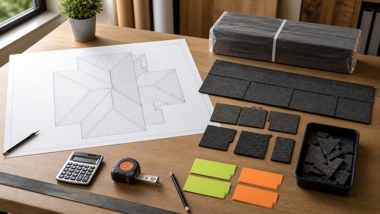
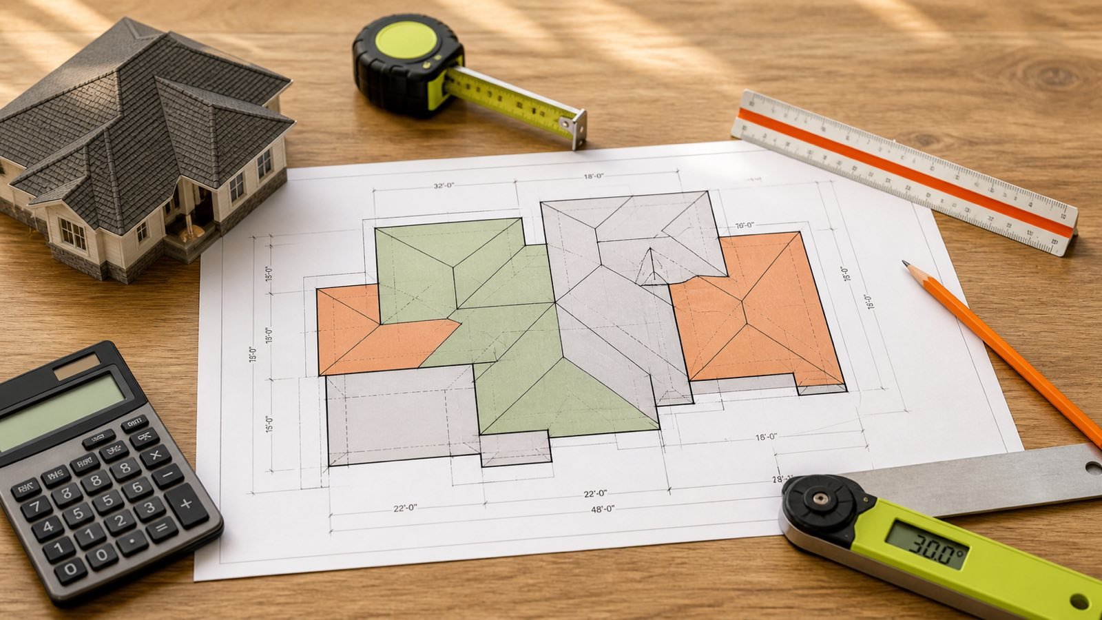
Draw the roof as seen from above and trace the outside edge of the covering. Add porches, garages, bays, canopies and wings that belong to the scope. Mark each change in roof boundary or pitch.
Divide the plan into rectangles, right triangles or trapezoids when those shapes fit the boundary. The British Columbia carpenter training module uses a plan sketch divided into rectangles and right triangles, with dimensions taken to the outside of the eave projection in its worked example.
- Write the project, building, drawing or observation date and units.
- Trace the outer roof edge, including each assigned overhang projection.
- Draw section boundaries so every plan zone appears once.
- Give each section an ID such as R-01 or R-02.
- Record its shape, dimensions, pitch and measurement source.
- Mark unresolved additions, hidden faces or uncertain intersections for checking.
A floor plan often stops at wall faces. A roof plan can extend beyond those faces. Copying floor length and width without the eave and rake projections can understate the roof boundary.
How should overhangs be measured?
Use the horizontal projection from the wall or other stated reference to the outer roof edge when the plan method needs a horizontal boundary. Record each side because front, rear and gable-end projections can differ.
Keep a sloped rafter-tail length out of a horizontal plan dimension. Convert or measure the horizontal projection first. On an L-shaped or stepped roof, add the overhang to each affected edge instead of adding one value to the building's overall length and width.
| Edge ID | Reference | Horizontal projection | Included section |
|---|---|---|---|
| E-01 | Front wall face to fascia | Measured value and unit | R-01 |
| E-02 | Rear wall face to roof edge | Measured value and unit | R-01 |
| R-01A | Gable wall to rake edge | Measured value and unit | R-01 |
The table is a record format, not a set of default dimensions. Use drawings, ground measurements or a suitable report for the actual values.
How do you check that roof sections cover the plan once?
Add the horizontal areas of all plan sections and compare that subtotal with an independently checked outer plan area where the geometry permits. A difference points to a gap, an overlap, an omitted projection or mismatched units.
Plan closure difference = checked outer plan area − sum of section plan areas
Example: a main plan section contains 96 m² and a non-overlapping canopy contains 12 m². The section total is 108 m². An independently checked outer boundary also contains 108 m², so the closure difference is 0 m².
A zero arithmetic difference does not prove that the section sketch matches the building. Compare section IDs with the current drawing, visible roof edges, additions and the stated work scope.
How do plan dimensions and pitch become sloped area?
Calculate each horizontal section by shape, then apply the pitch assigned to that section. Rise and run must use the same length unit.
Rectangle plan area = length × width
Right-triangle plan area = base × perpendicular height ÷ 2
Trapezoid plan area = (parallel side A + parallel side B) × perpendicular height ÷ 2
Pitch multiplier = √(1 + (rise ÷ run)²)
Sloped section area = plan section area × pitch multiplier
Use the pitch shown for the same section on a current plan or measurement record. A roof-style name such as gable or hip does not supply a pitch. Separate sections when their slopes differ.
Worked example: 2 plan sections with different pitches
A checked metric plan contains a 12 m × 8 m main section at 6:12 and a separate 4 m × 3 m canopy at 3:12. Both dimensions describe horizontal projections to their outer roof edges.
| Section | Plan area | Pitch | Multiplier | Sloped area |
|---|---|---|---|---|
| R-01 main | 12 × 8 = 96 m² | 6:12 | 1.118033989 | 107.331263 m² |
| R-02 canopy | 4 × 3 = 12 m² | 3:12 | 1.030776406 | 12.369317 m² |
| Total | 108 m² | Separate | Separate | 119.700580 m² |
Applying the 6:12 multiplier to both sections would assign the wrong slope to the canopy. Add the exact sloped section areas after each pitch calculation.
The rise/run notation acts as a ratio in this fixture. It does not approve a material or installation for either slope.
How does direct sloped-face measurement work?
Measure each face along the roof surface and calculate that face by its actual shape. Add the non-overlapping face areas. Do not apply a pitch multiplier because the sloped dimensions already contain the slope.
Example: 2 main faces each measure 32 ft along the eave by 18 ft from eave to ridge along the surface. An attached shed face measures 14 ft by 8 ft along its surface.
- Main faces: 32 × 18 × 2 = 1,152 ft².
- Shed face: 14 × 8 = 112 ft².
- Checked direct sloped-face total: 1,152 + 112 = 1,264 ft².
- Pitch multiplier: not applied.
Keep the sketch with the total. A single 1,264 ft² entry cannot show whether the shed face was omitted or a main face was counted twice.
How should dormers, hips and valleys enter the takeoff?
Add the roof faces of a dormer when they receive the measured covering. Split the surrounding main roof face so the dormer intersection does not create overlapping area. Complex intersections can justify a checked drawing takeoff or professional measurement report.
Hips and valleys are lines where roof faces meet. If your face or plan sections already partition the roof without gaps or overlaps, adding a generic hip or valley area counts geometry a second time. Record those lengths separately for the product and detail workflow.
IKO's guide separates roof-section area from ridge, hip, valley, eave and rake measurements. That distinction matters because field covering, cap, starter, flashing and edge products can use different dimensions and package records.
Should chimneys, skylights and vents be deducted?
Measure and identify every opening, then follow the project and product takeoff rule. Do not deduct an opening from geometric area and assume the same amount leaves the purchase quantity.
Openings can add flashing, underlayment treatment, cuts and short pieces. A large excluded roof zone and a small pipe penetration also create different quantity effects. Keep gross roof area, opening area and the approved order treatment on separate lines.
| Opening ID | Location | Plan or face dimensions | Area treatment | Separate detail |
|---|---|---|---|---|
| O-01 | R-01 | Measured values and state | Gross, deducted or retained under project rule | Flashing or curb record |
How should a roof measurement report be checked?
Confirm the report identifies the property or building, measurement date, units, roof boundary and whether the total is horizontal or sloped. Check overhangs, additions, dormers, openings and pitch treatment against current project information.
- Provider, report title, date and revision.
- Building or roof-zone identifier.
- Plan image or face schedule with section IDs.
- Units and rounding method.
- Horizontal projection, sloped area or both.
- Pitch for each section and the source of that pitch.
- Included and excluded edges, overhangs, openings and additions.
- Stated imagery, access, visibility or accuracy limitations.
Do not assign an accuracy percentage that the current report does not state. Tree cover, image angle, hidden additions, stale imagery and unclear boundaries require a check rather than a guessed correction factor.
Which roof measurement mistakes change the area?
- Using wall-line or floor dimensions without roof-edge projections.
- Adding a sloped overhang length to a horizontal plan dimension.
- Applying pitch to direct sloped-face dimensions.
- Using one pitch for sections with different slopes.
- Mixing feet and metres, or inches and feet, in one ratio or area line.
- Leaving a porch, bay, canopy, garage or addition outside the sketch.
- Drawing sections that overlap at an intersecting wing or dormer.
- Adding hip and valley area after adjoining faces already cover the plan.
- Deducting openings without recording the product and detail effect.
- Rounding each small section before adding exact compatible areas.
- Accepting an aerial total with no date, boundary or pitch state.
- Entering a roof for direct measurement without suitable access and fall controls.
What should you enter in the Roof Area Calculator?
Use projection mode for one rectangular horizontal section with one uniform rise/run pitch. Run separate calculations for sections with different pitches, then add their exact sloped areas.
Use checked-area mode after you total direct sloped faces or accept a report that already includes slope. The Roof Area Calculator keeps measured area, an entered allowance and package coverage on separate lines.
| Field | Record to pass |
|---|---|
| Mode | Projection and pitch, or checked sloped area |
| Section ID | Matching roof-plan or face-schedule row |
| Dimensions | Exact values, units and horizontal or sloped state |
| Pitch | Rise and run for that section when projection mode applies |
| Checked area | Unrounded sum with source and scope |
| Allowance | Project-approved value and reason, or 0% |
| Package coverage | Current exact-product record in compatible area units |
Safety and project limits
Use current drawings, suitable ground measurements or a qualified measurement service when they can provide the required record. Roof access exposes a person to edges, openings, fragile surfaces, weather and falling-object hazards.
OSHA's U.S. residential-construction guidance identifies serious fall hazards during roof sheathing and treats fall protection as part of roofing weatherproofing work. Employers must follow the applicable federal or state-plan requirements and select controls for the work and site.
This article does not inspect roof condition, approve a ladder or anchor, prepare a fall-protection plan, verify imagery, design framing, calculate loads, set drainage, select a roof covering or determine code compliance. Qualified people, current drawings, specifications, product instructions, permits and local requirements control those decisions.
Return to the Roofing Quantity Planning hub for the current calculator and supporting pages. The calculation methodology explains formula, unit and rounding checks. Report a source or arithmetic issue through the corrections route.
Sources and source scope
- BC Carpenter Apprenticeship Program, Level 2, Competency I-1: plan sketches, roof sections, eave projection and slope-based area workflow in its training context.
- IKO Blueprint for Roofing: adding roof-section areas and keeping linear roof details separate in the manufacturer's guide.
- OSHA Fall Protection in Residential Construction: U.S. residential roofing fall-hazard and protection context.
- NIST Handbook 44 (2026), Appendix C: foot, metre and square-area relationships.
Source scope: The British Columbia module supports its training method. IKO supports the named manufacturer's guide. OSHA supports U.S. workplace safety context. NIST supports unit conversion. The sources do not approve this roof's dimensions, access plan, product, allowance, package quantity or installation method.
Review note: Saleem Sial owns the research and editorial record. Source checks, independent geometry fixtures, editorial review, build validation, link crawl, schema review and rendered QA form the internal publication gate. Waseem Sial, External Reviewer and Engineer, is listed for ongoing external review; no completed review date is claimed.